Software multitasking timer on the MK
In various kinds of complexity of the implemented algorithms when programming MK, routine cyclic and not-so-difficult problems always arise. Some require increased accuracy, others do not have to have such a criterion. Hardware timers on board the MK can be a decent amount, for example STM32F4 - as many as 14 pieces, and this is not counting SysTick (system), and in others a pair of three for happiness: the same PIC16, for example.
To solve such unhurried, time-critical tasks, you can and should use a software timer based on one of the hardware. But first things first...
Ask the HUGLA what he thinks about it?
')
Without thinking, the search engine will produce something like this:
These articles served as a starting point in the implementation of the algorithm.
As a developer of automated process control systems, I often program PLCs of various companies. For any PLC in the development environment, libraries for software timers are stored. Almost all of them have the same type of functionality. The use of timers in the PLC program is required in many kinds of tasks, it makes no sense to describe all of them, so I will show a couple of examples from the industrial control system and these examples are “roughly porting” into this module.
What kind of timers are needed in this module? I opted for four types:
The first two timers clearly migrated from the PCS and PLC programming. The last two are a logical extension of the hardware timer of any MK. Consider each type of timer separately.
A trivial example of such a timer is the implementation of a time relay. The high (active) level signal arrives at the triggering (controlling) timer input and the timer obediently starts counting the time after which the active level at the input translates its output into the active state too. As soon as we remove the signal at the timer input, the output also becomes inactive. The timing chart is presented below.
In the world of MK, this timer will find its use if it is necessary to provide an anti-detour of “dry” contact, for detecting a long keystroke, etc. The scope of this timer is clearly not limited to this.
The timer is essentially the same as the first, but with the opposite logic. While active input, active and timer output. As soon as the input is low (not active), the timer starts counting down and at the end it resets its output to zero too. Here is his timeline.
This is necessary when it is necessary to stop the task not at the same time as its “parent”, but a little later. This type of timer may seem exotic to someone, when programming the MK, maybe so, but as they say, let it be.
Well, everything is trite here. Each overflow of this timer should trigger an event for which we perform this or that routine task. Interrogation of the sensor of the inertial medium, flashing of the LED, telling us that the MK is in “order”, for organizing equal intervals of time for all sorts of filters, etc. The timing chart below.
It is almost a complete copy of the cyclic, except for the fact that this type of timer switches itself off (stops) after operation. That is, they launched, counted their delay, set a flag (pointed to an event) and stopped themselves. Here is his chart.

Now all this is implemented in the code.
The name of the module speaks for itself. The module consists of two files: header and sorts.
Consider the leader:
This header contains a defayn indicating the number of software timers in the array. Announced enum for the "conscious" description of the timer operation modes. The following is the structure of the software timer. The only thing I would like to draw attention to is that the timer itself is 24-bit. In this structure, this allows the software timer to take up space of 8 bytes. 24 bits when the hardware timer overflows to 1 ms, it allows to achieve a delay of 4.66 hours or 16,777 seconds. Quite enough.
Functions a bit.
The main function that ensures the operation of the entire module:
This function should be called when the hardware timer overflows. It organizes the entire algorithm of the module. Let's look at the code:
In the loop we go through the entire array of timers. If the timer is empty = EMPTY, then go to the next timer. Depending on the mode of the timer, its own logic is organized.
The call of this function can be organized both from the interruption of the hardware timer and from the cycle in the main program by flag.
Here is an example of an interrupt for STM32.
But from the main loop:
Other functions:
This function sets the operation mode of a specific timer, sets the required delay.
Read the status of the timer status. Returns -1 if the specified timer is empty.
We initialize several timers with different modes. In the main cycle we use at our discretion:
If you need to stop the cyclic or single timer, then you need to reset the enable bit and set the disable bit.
Re-enable by setting trigger bit On.
Status reading can be done both as a function and directly reading the bit.
If the timer is no longer needed, then you can reduce the execution time of the function of processing the array of timers if you do not just stop the timer, but delete it, that is, put it into NULL mode. To do this, call the timer preparation function with the SWTIMER_MODE_EMPTY mode. Or just point it out.
The first two timers and the second two are slightly different in one structure, so as not to produce unnecessary functions, etc. You can download the program timer module from here .
This article is a recycled material from STM32. STM32F4 programming lessons. Lesson number 4. Software multitask timer STM32F4. the author of which I am.
Video demonstrating the functions of this module software multitask timer:
Probably that's all.
To solve such unhurried, time-critical tasks, you can and should use a software timer based on one of the hardware. But first things first...
Instead of the preface
Ask the HUGLA what he thinks about it?
')
Without thinking, the search engine will produce something like this:
- Software timers. Part 1
- Multitasking program timer.
- Multitasking software timer, ver 2.0
- Program timer. HAL Application
These articles served as a starting point in the implementation of the algorithm.
Foreword
As a developer of automated process control systems, I often program PLCs of various companies. For any PLC in the development environment, libraries for software timers are stored. Almost all of them have the same type of functionality. The use of timers in the PLC program is required in many kinds of tasks, it makes no sense to describe all of them, so I will show a couple of examples from the industrial control system and these examples are “roughly porting” into this module.
Mini TK
What kind of timers are needed in this module? I opted for four types:
- Delayed Timer
- Off-delay timer
- Cyclic timer
- Single timer
The first two timers clearly migrated from the PCS and PLC programming. The last two are a logical extension of the hardware timer of any MK. Consider each type of timer separately.
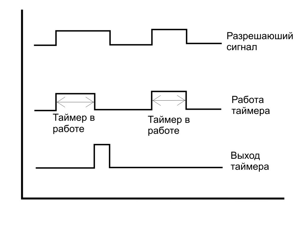
Delayed Timer
A trivial example of such a timer is the implementation of a time relay. The high (active) level signal arrives at the triggering (controlling) timer input and the timer obediently starts counting the time after which the active level at the input translates its output into the active state too. As soon as we remove the signal at the timer input, the output also becomes inactive. The timing chart is presented below.
In the world of MK, this timer will find its use if it is necessary to provide an anti-detour of “dry” contact, for detecting a long keystroke, etc. The scope of this timer is clearly not limited to this.
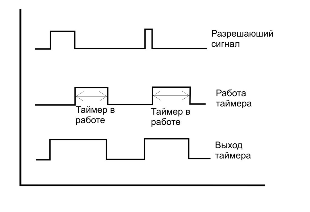
Off-delay timer
The timer is essentially the same as the first, but with the opposite logic. While active input, active and timer output. As soon as the input is low (not active), the timer starts counting down and at the end it resets its output to zero too. Here is his timeline.
This is necessary when it is necessary to stop the task not at the same time as its “parent”, but a little later. This type of timer may seem exotic to someone, when programming the MK, maybe so, but as they say, let it be.
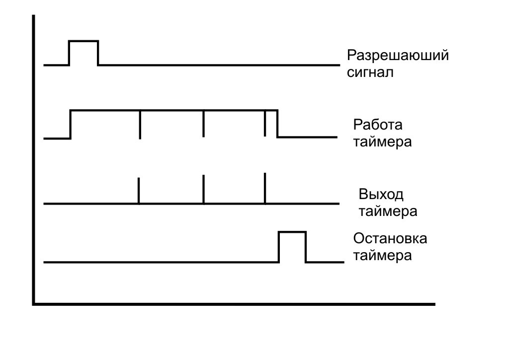
Cyclic timer
Well, everything is trite here. Each overflow of this timer should trigger an event for which we perform this or that routine task. Interrogation of the sensor of the inertial medium, flashing of the LED, telling us that the MK is in “order”, for organizing equal intervals of time for all sorts of filters, etc. The timing chart below.
Single timer
It is almost a complete copy of the cyclic, except for the fact that this type of timer switches itself off (stops) after operation. That is, they launched, counted their delay, set a flag (pointed to an event) and stopped themselves. Here is his chart.
Now all this is implemented in the code.
SwTimer module
The name of the module speaks for itself. The module consists of two files: header and sorts.
Consider the leader:
#ifndef SW_TIMER_H_ #define SW_TIMER_H_ #define SwTimerCount 64 // /* */ typedef enum { SWTIMER_MODE_EMPTY, SWTIMER_MODE_WAIT_ON, SWTIMER_MODE_WAIT_OFF, SWTIMER_MODE_CYCLE, SWTIMER_MODE_SINGLE } SwTimerMode; /* */ typedef struct { unsigned LocalCount:32; // unsigned Count:24; // unsigned Mode:3; // unsigned On:1; // unsigned Reset:1; // unsigned Off:1; // unsigned Out:1; // unsigned Status:1; // }SW_TIMER; #if (SwTimerCount>0) volatile SW_TIMER TIM[SwTimerCount]; // #endif void SwTimerWork(volatile SW_TIMER* TIM, unsigned char Count); // void OnSwTimer(volatile SW_TIMER* TIM, SwTimerMode Mode, unsigned int SwCount); // unsigned char GetStatusSwTimer(volatile SW_TIMER* TIM); // #endif /* SW_TIMER_H_ */ This header contains a defayn indicating the number of software timers in the array. Announced enum for the "conscious" description of the timer operation modes. The following is the structure of the software timer. The only thing I would like to draw attention to is that the timer itself is 24-bit. In this structure, this allows the software timer to take up space of 8 bytes. 24 bits when the hardware timer overflows to 1 ms, it allows to achieve a delay of 4.66 hours or 16,777 seconds. Quite enough.
Functions a bit.
The main function that ensures the operation of the entire module:
void SwTimerWork(volatile SW_TIMER* TIM, unsigned char Count); This function should be called when the hardware timer overflows. It organizes the entire algorithm of the module. Let's look at the code:
void SwTimerWork(volatile SW_TIMER* TIM, unsigned char Count){ unsigned short i=0; for (i=0; i<Count; i++){ if (TIM->Mode==SWTIMER_MODE_EMPTY) { TIM++; continue; } if (TIM->Mode==SWTIMER_MODE_WAIT_ON){ // if (TIM->On){ if (TIM->LocalCount>0) TIM->LocalCount--; else { TIM->Out=1; TIM->Status=1; } } else { TIM->Out=0; TIM->LocalCount=TIM->Count-1; } } if (TIM->Mode==SWTIMER_MODE_WAIT_OFF){ // if (TIM->On){ TIM->Out=1; TIM->Status=1; TIM->LocalCount=TIM->Count-1; } else { if (TIM->LocalCount>0) TIM->LocalCount--; else TIM->Out=0; } } if (TIM->Mode==SWTIMER_MODE_CYCLE){ if (TIM->Off){ if (TIM->On){ TIM->Off=0; if (TIM->LocalCount>0) TIM->LocalCount--; } } else{ if (TIM->LocalCount>0) { TIM->LocalCount--; TIM->Out=0; } else { TIM->Out=1; TIM->Status=1; TIM->LocalCount=TIM->Count-1; } } if (TIM->Reset){ TIM->LocalCount=TIM->Count-1; TIM->Out=0; TIM->Status=0; } } if (TIM->Mode==SWTIMER_MODE_SINGLE){ if (TIM->Off){ if (TIM->On){ TIM->Off=0; if (TIM->LocalCount>0) TIM->LocalCount--; } } else{ if (TIM->LocalCount>0) { TIM->LocalCount--; TIM->Out=0; } else { TIM->Out=1; TIM->Status=1; TIM->LocalCount=TIM->Count-1; TIM->Off=1; } } if (TIM->Reset){ TIM->LocalCount=TIM->Count-1; TIM->Out=0; TIM->Status=0; } } TIM++; } } In the loop we go through the entire array of timers. If the timer is empty = EMPTY, then go to the next timer. Depending on the mode of the timer, its own logic is organized.
The call of this function can be organized both from the interruption of the hardware timer and from the cycle in the main program by flag.
Here is an example of an interrupt for STM32.
/* USER CODE BEGIN 0 */ #include "sw_timer.h" /* USER CODE END 0 */ void SysTick_Handler(void) { /* USER CODE BEGIN SysTick_IRQn 0 */ /* USER CODE END SysTick_IRQn 0 */ HAL_IncTick(); HAL_SYSTICK_IRQHandler(); /* USER CODE BEGIN SysTick_IRQn 1 */ SwTimerWork(TIM,SwTimerCount); /* USER CODE END SysTick_IRQn 1 */ } But from the main loop:
/* USER CODE BEGIN 0 */ extern uint8_t FlagSwTimer; /* USER CODE END 0 */ void SysTick_Handler(void) { /* USER CODE BEGIN SysTick_IRQn 0 */ /* USER CODE END SysTick_IRQn 0 */ HAL_IncTick(); HAL_SYSTICK_IRQHandler(); /* USER CODE BEGIN SysTick_IRQn 1 */ FlagSwTimer=1; /* USER CODE END SysTick_IRQn 1 */ } /* */ while(1){ if (FlagSwTimer){ #if (SwTimerCount>0) // sw_timer.c SwTimerWork(TIM,SwTimerCount); #endif FlagSwTimer=0; } Other functions:
void OnSwTimer(volatile SW_TIMER* TIM, SwTimerMode Mode, unsigned int SwCount); This function sets the operation mode of a specific timer, sets the required delay.
unsigned char GetStatusSwTimer(volatile SW_TIMER* TIM); Read the status of the timer status. Returns -1 if the specified timer is empty.
Application
#define I_DI_READ_0() HAL_GPIO_ReadPin(GPIOA, GPIO_PIN_0) // OnSwTimer(&TIM[0],SWTIMER_MODE_WAIT_OFF,1000); OnSwTimer(&TIM[1],SWTIMER_MODE_SINGLE,1000); OnSwTimer(&TIM[2],SWTIMER_MODE_WAIT_ON,1000); OnSwTimer(&TIM[3],SWTIMER_MODE_CYCLE,1000); TIM[3].Off=0; TIM[3].On=1; // TIM[1].Off=0; TIM[1].On=1; // We initialize several timers with different modes. In the main cycle we use at our discretion:
while (1){ TIM[2].On=I_DI_READ_0(); // , HAL_GPIO_WritePin(GPIOD,GPIO_PIN_15,TIM[2].Out); // , TIM[0].On=I_DI_READ_0(); // , HAL_GPIO_WritePin(GPIOD,GPIO_PIN_14,TIM[0].Out); // , if (GetStatusSwTimer(&TIM[3])){ HAL_GPIO_TogglePin(GPIOD,GPIO_PIN_13); // , } if (GetStatusSwTimer(&TIM[1])){ HAL_GPIO_TogglePin(GPIOD,GPIO_PIN_12); // , } TIM[3].Reset=I_DI_READ_0(); // , } If you need to stop the cyclic or single timer, then you need to reset the enable bit and set the disable bit.
TIM[3].On=0; TIM[3].Off=1; Re-enable by setting trigger bit On.
Status reading can be done both as a function and directly reading the bit.
if (GetStatusSwTimer(&TIM[1])) // if (TIM[3].Status){ // TIM[3].Status=0; // , // , /*UserCode*/ } If the timer is no longer needed, then you can reduce the execution time of the function of processing the array of timers if you do not just stop the timer, but delete it, that is, put it into NULL mode. To do this, call the timer preparation function with the SWTIMER_MODE_EMPTY mode. Or just point it out.
OnSwTimer(&TIM[3],SWTIMER_MODE_EMPTY,0); // TIM[3].Mode=SWTIMER_MODE_EMPTY; // The first two timers and the second two are slightly different in one structure, so as not to produce unnecessary functions, etc. You can download the program timer module from here .
This article is a recycled material from STM32. STM32F4 programming lessons. Lesson number 4. Software multitask timer STM32F4. the author of which I am.
Video demonstrating the functions of this module software multitask timer:
Probably that's all.
Source: https://habr.com/ru/post/273077/
All Articles