Making a non-actinic LED light source
 On the manufacture of printed circuit boards using photoresist has already been told many times, including in the Habré . For many years (seriously) I was tormented by this, but I could not do absolutely nothing. Having spent half a jar of POSITIV donated many years ago, I received only one, half of which was paid. In 50% of cases, the resist was washed off all, in 50% - it was not washed off anywhere. Considering that in the future I will have to work with a photoresist in more difficult conditions (for my “homemade” microcircuits), I decided to eliminate all possible sources of problems.
One of these problems that can spoil all the work with a photoresist is the background light of the photoresist by indoor / outdoor lighting. It can be solved with the help of nonactinic lighting, because lighting that does not cause flare. For black and white photography for example - it was a red light. In this article I will talk about how to solve this problem.
Novolac photoresist (most resist for radio electronics are such) is sensitive to blue light, 450nm and shorter. And although blue light bulbs emit little light, in my case this can be a problem. In order to work comfortably - the light must be bright and, if possible, not dull red - you can gouge out the eyes in it. I tried to solve this problem using a handful of LEDs, which I was just lying around from another project.
What we need

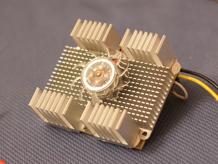
In order for the light to be as close to white as possible, I took 3x 3W green LEDs, 6x orange and 3x red ones. They cover almost the entire spectrum except the blue part. Because Each LED emits ~ 1.5W of heat - they all need to be put on thermal paste, and the printed circuit board should be cooled with radiators with active cooling (this problem does not make bright LED lamps). If the temperature of the LED chip is higher than 100 degrees, it will quickly degrade (1000 hours or less, while in normal mode it will be 50 thousand hours). Radiators are glued with hot glue.
')
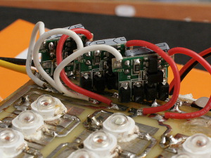 My fatal error is visible on the board - the metal “bottom” of the LEDs can be connected to one of the LED's leads (+ in some of my diodes), respectively, if the diode accidentally touches the board directly without thermal paste - then one diode can be connected to the driver rulers. This is how I killed one diode - the driver for one diode gave a current much higher than the nominal, and the diode died almost instantly. I had to scratch these common “polygons” to exclude such situations in the future. Drivers for diodes - at 0.65A from DX (on the far driver - you can see how I, instead of diodes, allowing to connect them in any polarity, solder the jumpers so as not to lose the extra 0.5W on the diodes).
All this connects to the power supply 12V, 4 diodes in series require about 10V. In principle, in this case it was possible to use a simpler linear regulator instead of a pulse one, the efficiency would be about the same.
Turn on

results
 It turned out that if there is a green part of the spectrum in the light source - the light immediately looks almost natural, the eyes do not strain and you can work comfortably. By the brightness of 0.65 * 2.5 * 12 = 20W LED lighting is more than enough, and an order of magnitude better than the standard red lamp for developing photo paper. With a photoresist, finally everything worked out perfectly. Well, as a free bonus - fun colorful shadows throughout the room because of the multi-colored point sources of light.
The photo on the right shows a hard-wired “daytime” white balance. The eye automatically adjusts the color, and the yellow tinge does not catch the eye.
Source: https://habr.com/ru/post/145165/
All Articles