ALU on 12 transistors (actually not)
What can be done on 12 transistors? If the circuit is analog, it could be, for example, a radio receiver or amplifier with decent performance. For the digital circuit it is too little. Even in such a simple chip as the ALU K155IP3 (74181), there are considerably more of them.
In fact, there are not 12, but 27 transistors here, but only 11 of them are used in the actual ALU (the twelfth transistor, which forcibly supplies a logical zero to the transfer input when selecting logical operations, is not installed). The remaining transistors are involved in the driver of the signals supplied to the inputs of the ALU. When an ALU is included in the transistor processor, the driver may not be needed if all the necessary signals are already formed there.
')
How to meet this quantity? First, to make ALU one-bit, and second, to reduce the number of operations to two arithmetic and five logical (for K155IP3 and both of them by 16, but here they are actually more), in the third ...
... perform an ALU using an unusual technology DCTL (direct coupled transistor logic), which allows to significantly reduce the number of components.
The simulation is performed in Falstad , this simulator is convenient because it shows the direction of current flow in the form of "running lights". Files: only full adder and ready ALU .
To begin with, we will build an “ALU” with one function — a full adder. We divide the scheme into two halves. The first is designed to prepare the input signals for the adder:

Switches can set two single-bit numbers - A and B and the transfer signal. Of these, the circuit forms four signals (the fourth is the same B, only inverted).
The second half of the circuit is the adder itself:
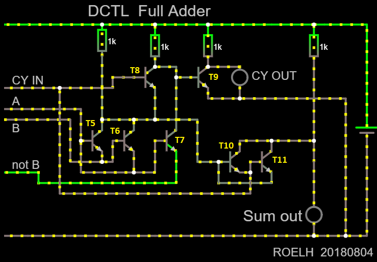
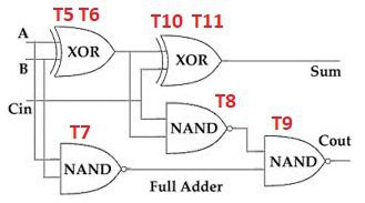
It is the implementation of the classic full adder. The block diagram additionally shows the distribution of transistors by logical elements:
In order to transform all this into a multifunctional ALU, first we will remake the driver of the input signals so that it forms not only the B value, but also the A value in the direct and inverted form:

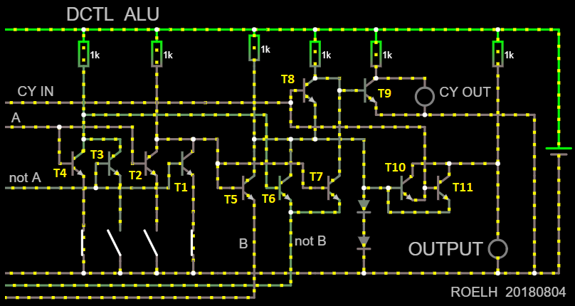
But since the author plans to apply his ALU as part of the processor on discrete components, such a driver may not be necessary: both values will be there in the direct and inverted form. Therefore, the transistors of the driver and are not included in the number of transistors ALU. Yes, and without a processor, you can simply take switches with flip contacts. And now - actually ALU:
With four switches, you can select the function performed by the ALU. Below are only 7 major:
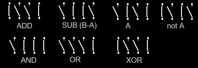
In order for the ALU not to be “spherical in a vacuum”, but to receive signals from the outside, the switches must be replaced with transistors. Since there is no transistor that forcibly supplies a logical zero to the transfer input when selecting logical functions, it is necessary to supply zero to this input in such cases manually.
Although the figure shows only 7 functions, you can try all 16 combinations of switch positions. Will be, in particular, the function of AND-NOT, OR-NOT, EXCLUSIVE OR-NOT, passing the signal B through, inverting the same signal.
Simulation can be a surprise. Did you know that a bipolar transistor can work by passing a current through it in the opposite direction? This happens with some combinations of input signals. In an analog amplifier, the gain is reduced, but the logic circuits continue to work in the same way as in normal mode.
The supply voltage is +5 V. In the simulator, transistors of general use of the NPN structure are selected.
The accumulator is obtained with a through transfer. The transfer signal has to go through transistors T8 and T9. If it is too slow, you must first check how the circuit connected to the emitter of the T8 transistor affects the operation of the circuit. Migration can also be made faster if you perform it for two bits at a time.
If you only need a full adder, the usual diode-transistor logic (DTL) will do. The transistors will need only two, but the diodes ... You can replace these transistors with lamps, you get what the author calls DVTL - diode-vacuum-tube-logic.
The upper part of the circuit produces an inverted transfer signal. The second calculates the inverted sum: SUM = ((A or B or C in) and / C out). This expression can also be represented as (A and B and C in).
The structural scheme is obtained as follows:
By adding a few more components, you can force a zero or one to the transfer input. Then the scheme will be able to perform the operation AND (at the transfer input is a unit, at the inverted transfer output is zero), and also OR (at the transfer input is zero, at the inverted transfer output is one).
To send a signal "inverted C out" to the input "C in" circuit for the next bit, you need a transistor inverter. Or you can accept the rule that direct and inverse logic alternates between bits.
All this can be turned into a valid ALU by calculating the resistor values and adding additional components to optimize the “responsiveness” of the circuit. Devices connected to the inputs must contain keys that close them to the ground (for diode “AND” inputs), or connecting them to the power plus (for diode “OR” inputs).
This is a very simple scheme, it does not implement fast transfer.
Source: https://habr.com/ru/post/448074/
All Articles