Developing a hexapod from scratch (part 5) - electronics
Hello! The development of the hexapod is nearing completion of the first combat version, and now it is time to describe all of its electronic content. At this stage of development, I will finally show all the sources of the project on github (links, as always, will be at the end). I also added HC-SR04 to detect obstacles, which was so lacking for visual satisfaction in the appearance of the hexapod. There will be some new video and you have a chance to kick me off on electronics.
View from the installed HC-SR04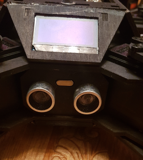
Initially, the case was designed for separate power and control boards, in order to place one in the center of the case closer to the battery, and the second to be taken up for easy debugging. And so let's get started.
Control block
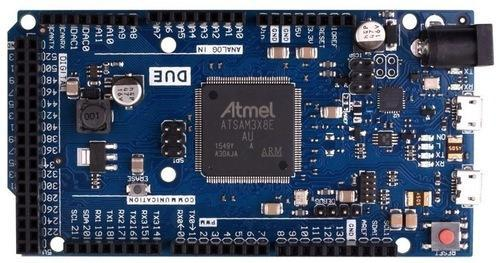
The control unit is the “brain” of the hexapod based on the SAM3X8E controller and consists of two boards: a board with a controller and a distribution board. The board with the controller is used already finished (picture below), but the distribution board will have to be made. Perhaps in the future I will order a production fee with a place for the controller to remove the sandwich.
The main purpose of the distribution board is to power the “light” peripherals, the controller and distribute the signals along its pins. I made a list of my requirements for this board:
- Possibility of installation on the board HLK-RM04 (UART-WIFI converter);
- Ability to connect I2C display;
- The ability to connect HC-SR04;
- The ability to measure battery voltage = power supply voltage;
- The ability to measure the supply voltage of the periphery and the HLK-RM04;
- Connecting tweeters to indicate battery discharge;
- LED indication of the system status: something important has fallen off (configuration is not correct or something else), something unimportant has fallen off (display for example), everything is OK;
Having a little bit decided on the element base and having estimated the possibilities of my stash with crumbling, I started immediately making the PCB layout without creating its concept. Earned everything from the first time and did not find any jambs in the work. The layout is as follows:
')
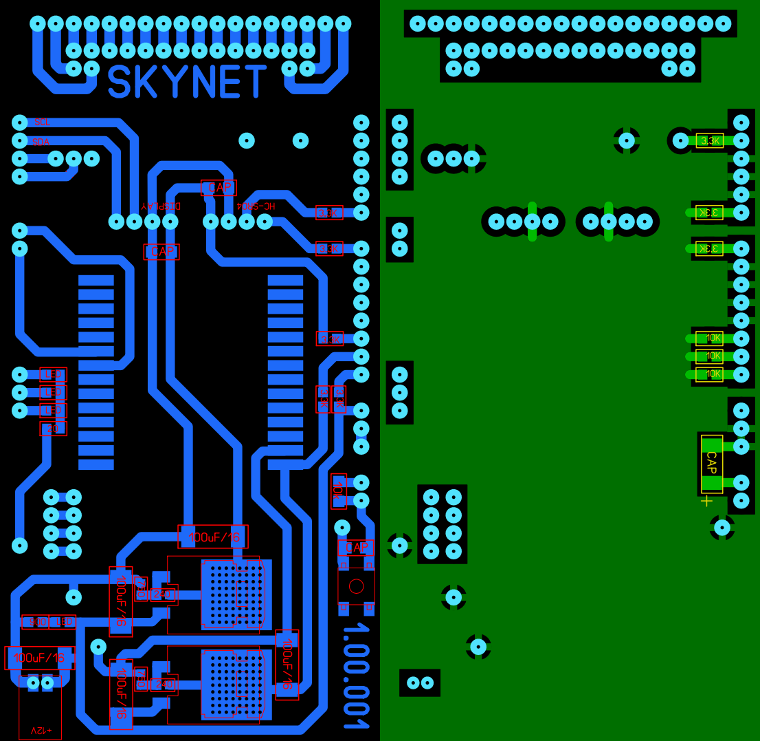
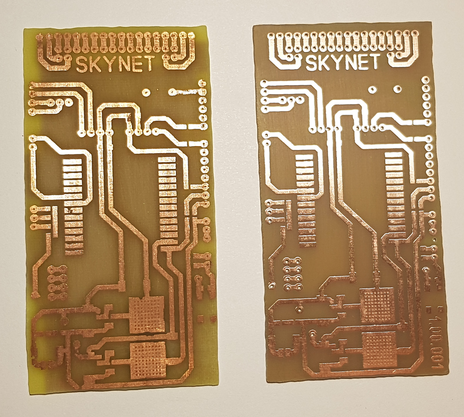
The tracks were specially made wide, so that in the manufacturing process there were no problems. I decided to make the board with LUT, it was good only from 2 times. Under the spoiler photos for comparing unsuccessful and successful options (left unsuccessful, right right).
Photos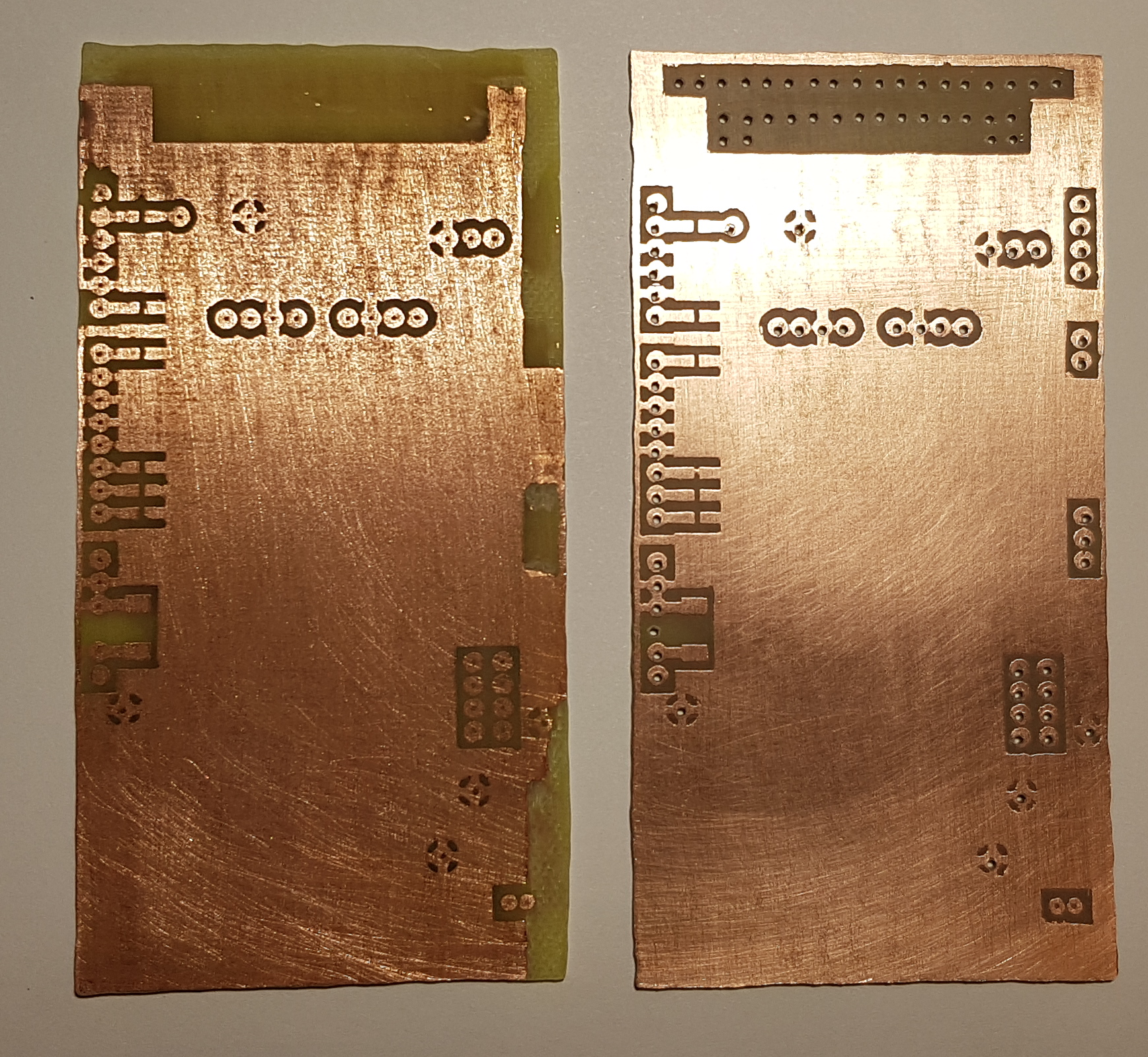
Well, then everything according to the instructions - we puddle the board, drill holes and fill up the components. The result was not long in coming:
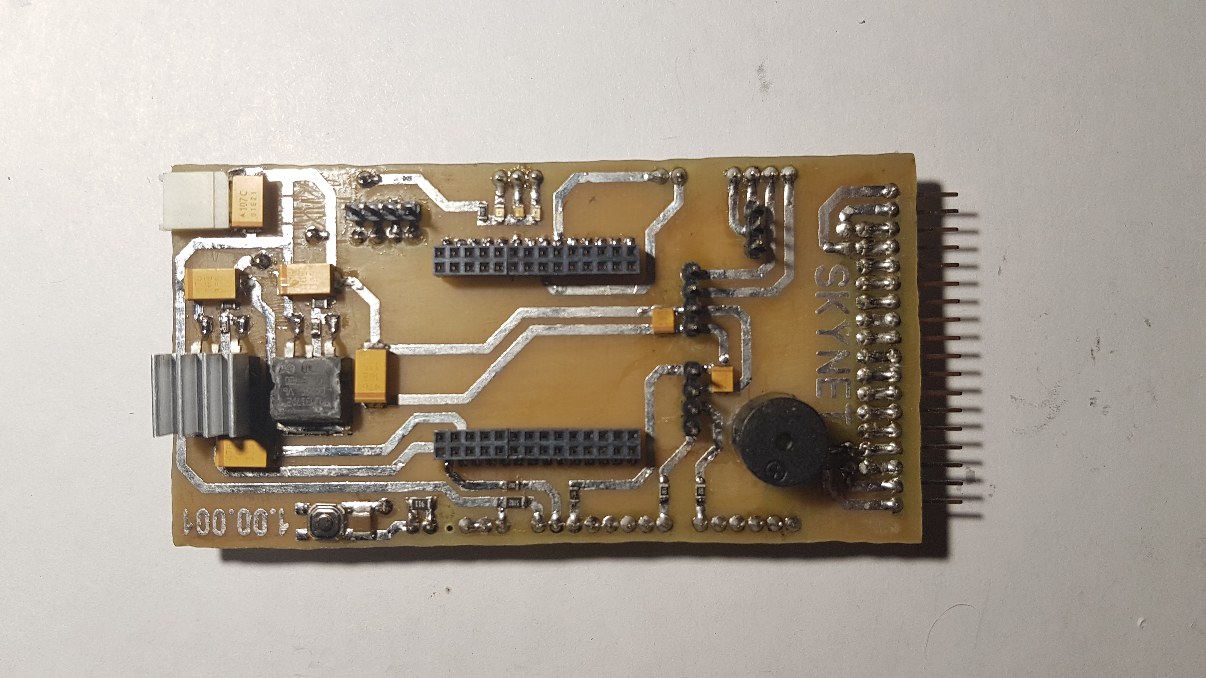
In the center, the HLK-RM04 is inserted, to the right, in the comb, to the power supply board, to the left, power is supplied. The voltage on the board is measured by a simple voltage divider. With long work (30–40 minutes), the voltage regulator for the HLK-RM04 heats up noticeably and I just in case put the radiator.
HLK-RM04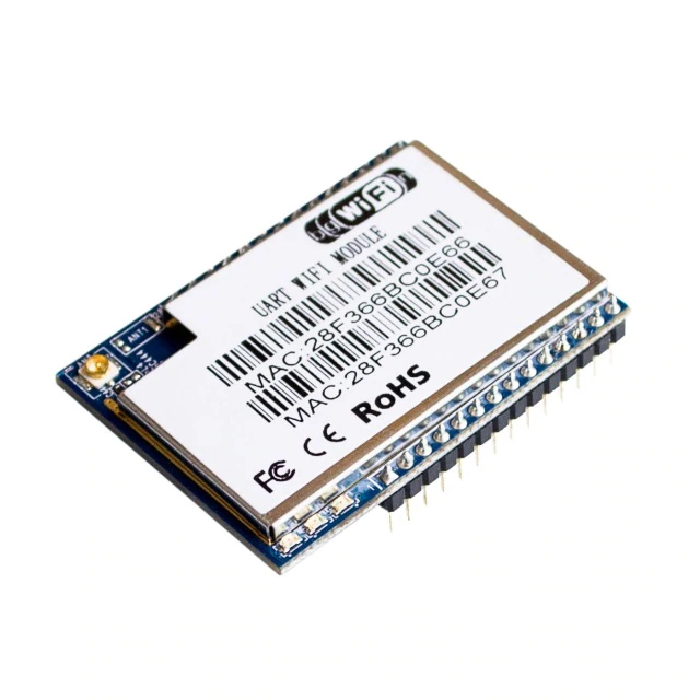
Power board
The total current consumption (peak) of the drives is approximately 30A (on average ~ 1.3A per drive) under heavy load, while walking 10-13A, at rest - 5-6A. Measurements conducted empirically by a multimeter.
I decided to make the power separate for each drive based on linear voltage regulators, i.e. 18 linear voltage regulators - one for each drive. LM317D2T-TR configured to issue 5V are used as linear regulators. There are several reasons for using 18 linear voltage regulators and using regulators in principle:
- Directly connect the drives to the battery is impossible, for them the maximum allowable supply voltage of 6V;
- Relative independence of the speed \ force of the drives from the input voltage;
- Linear regulators I have heaps. I once bought them on Ali with a package of 70pcs (the item made the greatest contribution to the decision);
- I have not found a linear voltage regulator for such a current;
- I have not found a compact and light DC-DC circuit for such a current;
- The option of parallel connection of regulators is rather doubtful;
- The option “linear regulator + amplifying transistor” deprives the power supply circuit of all protective functions that the linear regulator gives (at least that's what people write and in this case I agree with them);
- I am rather poorly versed in the design of switching power supplies;
The board is very simple and I also did not draw a concept for it, and the desire to see the result as soon as possible also made itself felt. The layout is as follows:
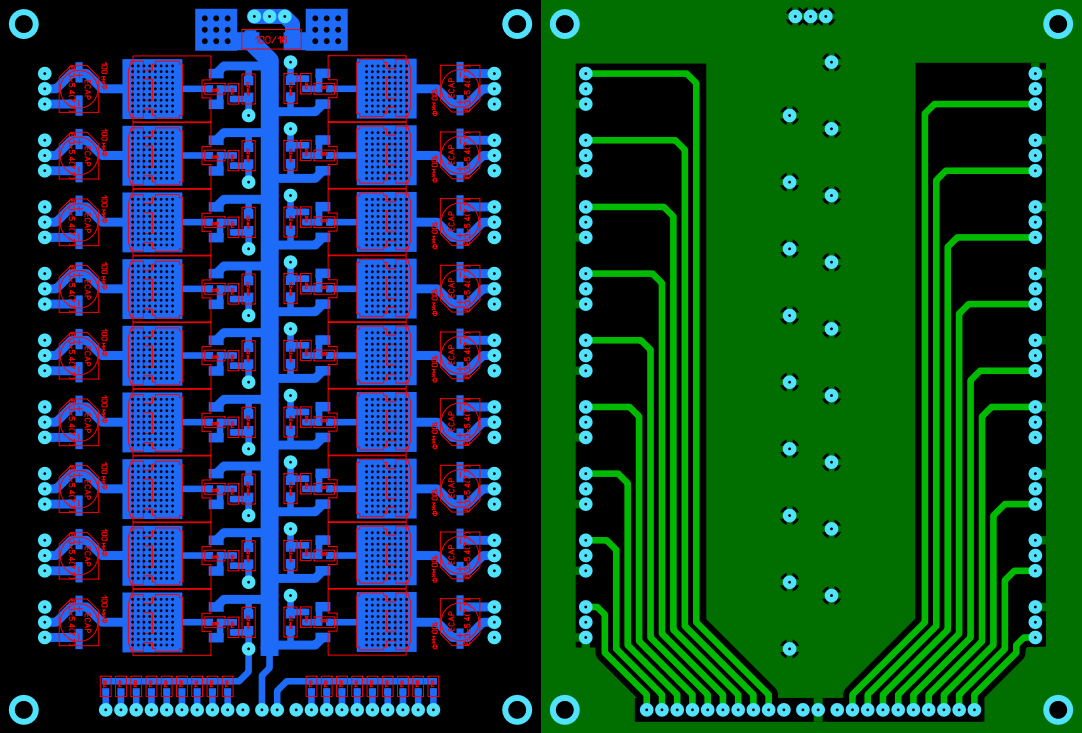
On the top there are contact pads for soldering wires to the battery, from the bottom of the comb under the cable and power supply to the control unit, and on the sides are connected drives. Initially, I also wanted to make it possible to measure the amount of current consumed by each servo and measure the temperature of the board, but I decided not to complicate it yet.
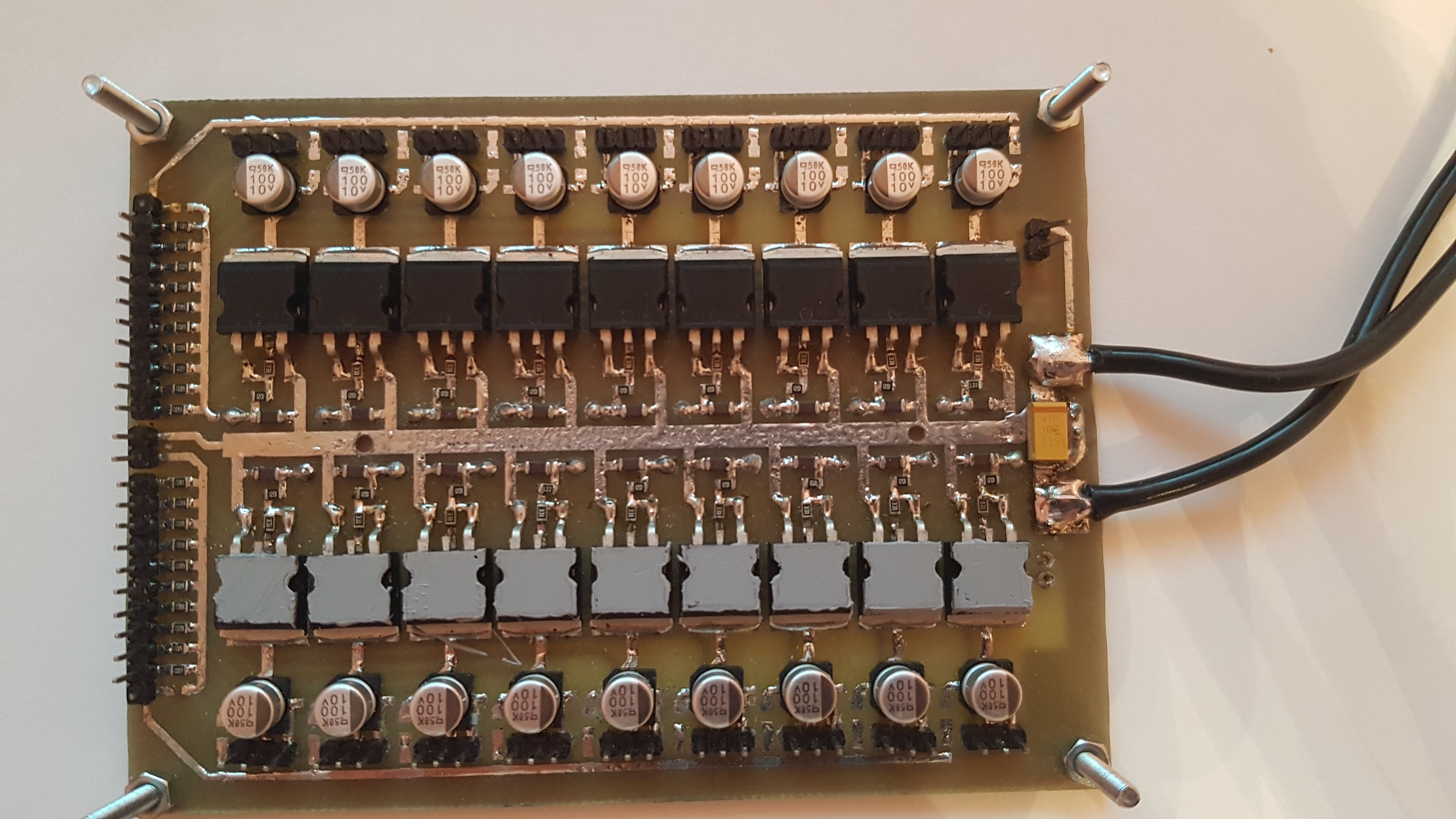
The payment turned out simple and reliable, there is nothing to break there. Conducted load tests at an input voltage of 11.1V (3S LiPo) and 7.4V (2S LiPo). At an input voltage of 11.1V, as expected, the regulators heated up too much and the temperature protection was triggered while walking (the radiator did not save, respectively, and also the SMD regulators), which forced me to reduce the input voltage. At a voltage of 7.4V, the regulators are warm and during long walking the protection does not work anymore - what you need.
The board was also manufactured by LUT and it turned out pretty good the first time. Unfortunately, there is only a photo of the experimental version of the board, but I didn’t really like to disassemble the new 4 hours from the case for the sake of the photo (you need to disassemble about 70% of the case). The difference between the old and the new is only in the absence of holes along the center line of the board (merry experiments were carried out).
Some video and source
- Firmware (project in AtmelStudio on C)
- Management Program (Qt / QML for Android and Windows)
- All sorts of documentation
- PCB distribution and power
- Blueprints
HC-SR04 performance testing
The ratio of my cat to the hexapod
The first party down the street
Links to other development stages
Part 1 - Design
Part 2 - Build
Part 3 - Kinematics
Part 4 - Mathematics of trajectories and sequences
Source: https://habr.com/ru/post/448058/
All Articles