Creating plug-ins for AutoCAD using the .NET API (part 4 - inserting primitive objects)
Welcome to the fourth part of the development cycle for plug-ins for AutoCAD. The previous articles dealt with general issues of creating a plug-in - and now, armed with this knowledge, you can finally move on to the main task facing the AutoCAD user: drawing editing.
In this article, the simplest operations that a developer may require are: creating and placing graphic primitives on a drawing (line, polyline, circle, ellipse, and circle).
If a dear reader wants to repeat the examples presented on his computer, then to simplify life, it is worth exploring autoloading plugins. For example, you can read the post Namolem - there is a mention of this.
')
Summarize the essence of the problem: since after loading the plugin it is impossible to “unload” it, the only way to launch the plugin whose code has been changed is to close AutoCAD, then launch it again and reload the plugin. This trivial operation takes a couple of minutes on the force, but after fifty or one hundred repetitions, it begins to annoy wildly, I would even say - enrage .
The autoload of the plug-in allows you to exclude one of the stages of this procedure, which will help to save a couple ofthousand nerve cells.
Adding a line to a drawing is easy. Let's do this by using as an example the example set out in the documentation ( translation ).
The code itself is extremely simple, there is nothing special to describe in detail here.
First , we start a transaction (what it is and why it is needed, was discussed in the last article).
Secondly , we open the model space (
Third , we create a graphic object (in our case, a line), specifying the necessary parameters in the constructor (in our case, the starting and ending points).
Fourth , we must set all properties for the object. In this example, we set default values for all properties by calling the
Fifthly , it is necessary to add the created object to the model space (in other words, to the drawing). This is done using the
Sixthly , it is necessary to add the created object to the transaction within which we work. To do this, use the
Finally , after performing all the operations we need, we must commit the transaction by calling the
After compiling the project, launch AutoCAD, load our plugin and execute the HabrCommand command. The result is simple - but, I hope, it is understandable and predictable.

If, after launching the command, the line on the screen did not appear - do not rush to get upset. Instead, make sure that the center of coordinates - the point (0; 0) - is within the visible work area. In addition, it makes sense to change the scale by turning the mouse wheel.
For novice users of AutoCAD, it may come as a surprise that the scaling of the drawing occurs within certain limits. Simply put, it is impossible to go from a scale of 1000% to a scale of 1% on the move - after a couple of mouse wheel scrolls, the scale will “rest” on an invisible limiter. To continue drawing scaling, you must run the REGEN command in the AutoCAD command line.
Again, an example is in the documentation ( translation ).
Result:

There is nothing to clarify here. If desired, by adding new points a polyline can be turned into atrolleybus of a rather complex geometric shape - for example, an asterisk ...
Consider an example of adding a circle to a drawing diligently reprinted from the documentation (links were above).
There should be no difficulties with adding a circle to the drawing: all that is needed is to set the center and the radius.
Result:

Creating an ellipse is somewhat different from creating a circle: its parameters must be explicitly specified in the constructor (details are given here ).
Result (blue line added for explanation):

When creating an ellipse, we set the following parameters to it:
To draw the whole shape, you need to "run" a full circle, that is, 360 degrees, or 2pi (as in the polar coordinate system). If we specify less, we get only part of the shape.
To create a circle, you can use the hatching -
The procedure will be as follows:
Steps popribilos, but they are all simple.
Result:
The part where we create the border of the hatching should not cause any problems - it’s just a circle that we created and placed on the drawing. The part where the hatching is created and added to the drawing does not need any explanations either. The part where we set the hatching parameters remains. Let us dwell on it in more detail.
First, we call the
Then we specify the type of hatching using the
After setting the type of hatching, I indicated its color (the
Then the
The “Define the Hatch Boundaries (.NET)” section of the documentation ( translation ) states that the
The
Now all parameters of the created hatching are defined. In order for the hatching to be displayed on the screen, AutoCAD must perform the necessary calculations. To perform these calculations, you must call the function
All actions needed to create hatching are performed. We have already added it to the drawing and to the transaction in step 6. Now it remains to fix the transaction so that AutoCAD saves the changes we made.
The article was quite simple - but, I hope, everything is clear and accessible. The AutoCAD .NET API allows you to draw more complex shapes, such as arcs and splines, but I haven’t been able to work with them. Information about this, if necessary, can be found in the documentation ( translation ).
Actually, I was planning to tell here about adding text and creating simple blocks, but something already came along pretty well. So these questions will be covered in the next article.
Thanks for attention!
Any feedback, comments and suggestions are welcome in the comments.)
In this article, the simplest operations that a developer may require are: creating and placing graphic primitives on a drawing (line, polyline, circle, ellipse, and circle).
public static string disclaimer = " AutoCAD. – ."; Before work
If a dear reader wants to repeat the examples presented on his computer, then to simplify life, it is worth exploring autoloading plugins. For example, you can read the post Namolem - there is a mention of this.
')
Summarize the essence of the problem: since after loading the plugin it is impossible to “unload” it, the only way to launch the plugin whose code has been changed is to close AutoCAD, then launch it again and reload the plugin. This trivial operation takes a couple of minutes on the force, but after fifty or one hundred repetitions, it begins to annoy wildly, I would even say - enrage .
The autoload of the plug-in allows you to exclude one of the stages of this procedure, which will help to save a couple of
Line
Adding a line to a drawing is easy. Let's do this by using as an example the example set out in the documentation ( translation ).
Plugin code:
using System; using System.IO; using Autodesk.AutoCAD.Runtime; using Autodesk.AutoCAD.DatabaseServices; using Autodesk.AutoCAD.Geometry; using Autodesk.AutoCAD.ApplicationServices; using acad = Autodesk.AutoCAD.ApplicationServices.Application; namespace HabrPlug_Primitives { public class ClassMyAutoCADDLL { public class Commands : IExtensionApplication { // AutoCAD "HabrCommand" [CommandMethod("HabrCommand")] public void HabrCommand() { // Document acDoc = acad.DocumentManager.MdiActiveDocument; Database acCurDb = acDoc.Database; // using (Transaction acTrans = acCurDb.TransactionManager.StartTransaction()) { // BlockTable acBlkTbl; acBlkTbl = acTrans.GetObject(acCurDb.BlockTableId, OpenMode.ForRead) as BlockTable; // (Model Space) - BlockTableRecord acBlkTblRec; acBlkTblRec = acTrans.GetObject(acBlkTbl[BlockTableRecord.ModelSpace], OpenMode.ForWrite) as BlockTableRecord; // Line acLine = new Line(new Point3d(25, 25, 0), new Point3d(33, 33, 0)); // acLine.SetDatabaseDefaults(); // acBlkTblRec.AppendEntity(acLine); // acTrans.AddNewlyCreatedDBObject(acLine, true); // acTrans.Commit(); } } // Initialize() Terminate() , IExtensionApplication public void Initialize() { } public void Terminate() { } } } } When creating a project, of course, do not forget about all sorts of stuff ...)
First, you need to specify the required version of the .NET Framework (in my case it is .NET Framework 3.5).
Secondly, you need to add links to AcDbMgd.dll and AcMgd.dll libraries and in the properties of these links to prevent copying of libraries to the target folder of the project (set the
Secondly, you need to add links to AcDbMgd.dll and AcMgd.dll libraries and in the properties of these links to prevent copying of libraries to the target folder of the project (set the
CopyLocal parameter to False ).The code itself is extremely simple, there is nothing special to describe in detail here.
First , we start a transaction (what it is and why it is needed, was discussed in the last article).
Secondly , we open the model space (
Model Space ) - this is, in fact, our drawing. A clearer definition of Model Space can be found here and there . Since we are going to add a new object to the drawing, we need to request read and write access ( OpenMode.ForWrite ).Third , we create a graphic object (in our case, a line), specifying the necessary parameters in the constructor (in our case, the starting and ending points).
Fourth , we must set all properties for the object. In this example, we set default values for all properties by calling the
SetDatabaseDefaults() function to do this. A mean male description of this function can be found in the ObjectARX Reference .Nb:
in practice, for simple cases, the call of this function can be neglected, however, it is believed that it is better not to do so.
Fifthly , it is necessary to add the created object to the model space (in other words, to the drawing). This is done using the
AppendEntity() function.Sixthly , it is necessary to add the created object to the transaction within which we work. To do this, use the
AddNewlyCreatedDBObject() function, which was already discussed in the previous article.Finally , after performing all the operations we need, we must commit the transaction by calling the
Commit() method.After compiling the project, launch AutoCAD, load our plugin and execute the HabrCommand command. The result is simple - but, I hope, it is understandable and predictable.
If, after launching the command, the line on the screen did not appear - do not rush to get upset. Instead, make sure that the center of coordinates - the point (0; 0) - is within the visible work area. In addition, it makes sense to change the scale by turning the mouse wheel.
For novice users of AutoCAD, it may come as a surprise that the scaling of the drawing occurs within certain limits. Simply put, it is impossible to go from a scale of 1000% to a scale of 1% on the move - after a couple of mouse wheel scrolls, the scale will “rest” on an invisible limiter. To continue drawing scaling, you must run the REGEN command in the AutoCAD command line.
Nb:
from personal experience: if the programmer completely stumbled, and it is already incomprehensible what objects are created and whether they are created at all, you can open a clean drawing, execute an interesting piece of code on it and select all objects in the drawing by pressing the key combination “Ctrl + A”. After that, to find the created objects, as a rule, is not difficult.
Let's refresh by example.
Let's refresh by example.
Picture TO:
Well, where is the line here?)
Well, where is the line here?)
Painting AFTER:
The line with the head pretended by a speck of dust on the monitor gives out a blue small square and the appeared object properties window.
The line with the head pretended by a speck of dust on the monitor gives out a blue small square and the appeared object properties window.
Polyline
Again, an example is in the documentation ( translation ).
Command Code:
[CommandMethod("HabrCommand")] public void HabrCommand() { // Document acDoc = acad.DocumentManager.MdiActiveDocument; Database acCurDb = acDoc.Database; // using (Transaction acTrans = acCurDb.TransactionManager.StartTransaction()) { // BlockTable acBlkTbl; acBlkTbl = acTrans.GetObject(acCurDb.BlockTableId, OpenMode.ForRead) as BlockTable; // (Model Space) - BlockTableRecord acBlkTblRec; acBlkTblRec = acTrans.GetObject(acBlkTbl[BlockTableRecord.ModelSpace], OpenMode.ForWrite) as BlockTableRecord; // Polyline acPolyline = new Polyline(); // acPolyline.SetDatabaseDefaults(); // acPolyline.AddVertexAt(0, new Point2d(2, 4), 0, 0, 0); acPolyline.AddVertexAt(1, new Point2d(4, 8), 0, 0, 0); acPolyline.AddVertexAt(2, new Point2d(6, 6), 0, 0, 0); acPolyline.AddVertexAt(3, new Point2d(8, 11), 0, 0, 0); // acBlkTblRec.AppendEntity(acPolyline); // acTrans.AddNewlyCreatedDBObject(acPolyline, true); // acTrans.Commit(); } } Result:
There is nothing to clarify here. If desired, by adding new points a polyline can be turned into a
... or is it a trolley bus?

Yes, I also noticed that the trolley has no wheels. But we still don’t know how to draw a circle, but square wheels ... No, let’s go better.
[CommandMethod("HabrCommand")] public void HabrCommand() { // Document acDoc = acad.DocumentManager.MdiActiveDocument; Database acCurDb = acDoc.Database; // using (Transaction acTrans = acCurDb.TransactionManager.StartTransaction()) { // BlockTable acBlkTbl; acBlkTbl = acTrans.GetObject(acCurDb.BlockTableId, OpenMode.ForRead) as BlockTable; // (Model Space) - BlockTableRecord acBlkTblRec; acBlkTblRec = acTrans.GetObject(acBlkTbl[BlockTableRecord.ModelSpace], OpenMode.ForWrite) as BlockTableRecord; // Polyline acPolyline = new Polyline(); // acPolyline.SetDatabaseDefaults(); // acPolyline.AddVertexAt(0, new Point2d(100, 100), 0, 0, 0); acPolyline.AddVertexAt(1, new Point2d(100, 650), 0, 0, 0); acPolyline.AddVertexAt(2, new Point2d(1050, 650), 0, 0, 0); acPolyline.AddVertexAt(3, new Point2d(650, 1150), 0, 0, 0); acPolyline.AddVertexAt(4, new Point2d(1050, 650), 0, 0, 0); acPolyline.AddVertexAt(5, new Point2d(2050, 650), 0, 0, 0); acPolyline.AddVertexAt(6, new Point2d(2050, 100), 0, 0, 0); acPolyline.AddVertexAt(7, new Point2d(1950, 100), 0, 0, 0); acPolyline.AddVertexAt(8, new Point2d(1950, 400), 0, 0, 0); acPolyline.AddVertexAt(9, new Point2d(1800, 400), 0, 0, 0); acPolyline.AddVertexAt(10, new Point2d(1800, 100), 0, 0, 0); acPolyline.AddVertexAt(11, new Point2d(1950, 100), 0, 0, 0); acPolyline.AddVertexAt(12, new Point2d(1700, 100), 0, 0, 0); acPolyline.AddVertexAt(13, new Point2d(1660, 170), 0, 0, 0); acPolyline.AddVertexAt(14, new Point2d(1600, 225), 0, 0, 0); acPolyline.AddVertexAt(15, new Point2d(1500, 225), 0, 0, 0); acPolyline.AddVertexAt(16, new Point2d(1440, 170), 0, 0, 0); acPolyline.AddVertexAt(17, new Point2d(1400, 100), 0, 0, 0); acPolyline.AddVertexAt(18, new Point2d(850, 100), 0, 0, 0); acPolyline.AddVertexAt(19, new Point2d(1200, 100), 0, 0, 0); acPolyline.AddVertexAt(20, new Point2d(1200, 400), 0, 0, 0); acPolyline.AddVertexAt(21, new Point2d(1000, 400), 0, 0, 0); acPolyline.AddVertexAt(22, new Point2d(1000, 100), 0, 0, 0); acPolyline.AddVertexAt(23, new Point2d(1100, 100), 0, 0, 0); acPolyline.AddVertexAt(24, new Point2d(1100, 400), 0, 0, 0); acPolyline.AddVertexAt(25, new Point2d(1100, 100), 0, 0, 0); acPolyline.AddVertexAt(26, new Point2d(850, 100), 0, 0, 0); acPolyline.AddVertexAt(27, new Point2d(810, 170), 0, 0, 0); acPolyline.AddVertexAt(28, new Point2d(750, 225), 0, 0, 0); acPolyline.AddVertexAt(29, new Point2d(650, 225), 0, 0, 0); acPolyline.AddVertexAt(30, new Point2d(590, 170), 0, 0, 0); acPolyline.AddVertexAt(31, new Point2d(550, 100), 0, 0, 0); acPolyline.AddVertexAt(32, new Point2d(100, 100), 0, 0, 0); acPolyline.AddVertexAt(33, new Point2d(450, 100), 0, 0, 0); acPolyline.AddVertexAt(34, new Point2d(450, 400), 0, 0, 0); acPolyline.AddVertexAt(35, new Point2d(250, 400), 0, 0, 0); acPolyline.AddVertexAt(36, new Point2d(250, 100), 0, 0, 0); acPolyline.AddVertexAt(37, new Point2d(350, 100), 0, 0, 0); acPolyline.AddVertexAt(38, new Point2d(350, 400), 0, 0, 0); // acBlkTblRec.AppendEntity(acPolyline); // acTrans.AddNewlyCreatedDBObject(acPolyline, true); // acTrans.Commit(); } } Yes, I also noticed that the trolley has no wheels. But we still don’t know how to draw a circle, but square wheels ... No, let’s go better.
Circle
Consider an example of adding a circle to a drawing diligently reprinted from the documentation (links were above).
Command Code:
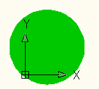
[CommandMethod("HabrCommand")] public void HabrCommand() { // Document acDoc = acad.DocumentManager.MdiActiveDocument; Database acCurDb = acDoc.Database; // using (Transaction acTrans = acCurDb.TransactionManager.StartTransaction()) { // BlockTable acBlkTbl; acBlkTbl = acTrans.GetObject(acCurDb.BlockTableId, OpenMode.ForRead) as BlockTable; // (Model Space) - BlockTableRecord acBlkTblRec; acBlkTblRec = acTrans.GetObject(acBlkTbl[BlockTableRecord.ModelSpace], OpenMode.ForWrite) as BlockTableRecord; // Circle acCircle = new Circle(); // acCircle.SetDatabaseDefaults(); acCircle.Center = new Point3d(2.5, 3.14, 0); acCircle.Radius = 4.25; // acBlkTblRec.AppendEntity(acCircle); // acTrans.AddNewlyCreatedDBObject(acCircle, true); // acTrans.Commit(); } } There should be no difficulties with adding a circle to the drawing: all that is needed is to set the center and the radius.
Result:
Nb:
When working with indirect lines, it is worth remembering that in some cases they may not be displayed correctly on the screen.
In particular, if in this example you execute the HabrCommand command with a large distance and then greatly increase the scale (to bring the elements of the drawing closer), then the effect shown in the picture below will be observed. Those who often work with AutoCAD probably got used to this — but for the first time I saw what my circle had become, I had been looking for a mistake in the code for a long time and had killed several hours trying to “improve the rendering accuracy”.)

To restore the original shape of a circle, you can use the REGEN command in the AutoCAD command line:

Once again, I emphasize that this effect occurs exclusively when displayed . Inside a document, a circle is always a circle, no matter who it looks like outside.
In particular, if in this example you execute the HabrCommand command with a large distance and then greatly increase the scale (to bring the elements of the drawing closer), then the effect shown in the picture below will be observed. Those who often work with AutoCAD probably got used to this — but for the first time I saw what my circle had become, I had been looking for a mistake in the code for a long time and had killed several hours trying to “improve the rendering accuracy”.)
To restore the original shape of a circle, you can use the REGEN command in the AutoCAD command line:
Once again, I emphasize that this effect occurs exclusively when displayed . Inside a document, a circle is always a circle, no matter who it looks like outside.
Ellipse
Creating an ellipse is somewhat different from creating a circle: its parameters must be explicitly specified in the constructor (details are given here ).
Command Code:
[CommandMethod("HabrCommand")] public void HabrCommand() { // Document acDoc = acad.DocumentManager.MdiActiveDocument; Database acCurDb = acDoc.Database; // using (Transaction acTrans = acCurDb.TransactionManager.StartTransaction()) { // BlockTable acBlkTbl; acBlkTbl = acTrans.GetObject(acCurDb.BlockTableId, OpenMode.ForRead) as BlockTable; // (Model Space) - BlockTableRecord acBlkTblRec; acBlkTblRec = acTrans.GetObject(acBlkTbl[BlockTableRecord.ModelSpace], OpenMode.ForWrite) as BlockTableRecord; // Point3d center = Point3d.Origin; Vector3d normal = Vector3d.ZAxis; Vector3d majorAxis = 100 * Vector3d.XAxis; double radiusRatio = 0.5; double startAng = 0.0; double endAng = Math.PI * 2; // , Ellipse acEllipse = new Ellipse(center, normal, majorAxis, radiusRatio, startAng, endAng); // acBlkTblRec.AppendEntity(acEllipse); // acTrans.AddNewlyCreatedDBObject(acEllipse, true); // acTrans.Commit(); } } Result (blue line added for explanation):
When creating an ellipse, we set the following parameters to it:
- The center (center) of the ellipse - this is all clear.
- Normal (normal) - a vector perpendicular to the plane of the ellipse. As we add an object to the XY plane, the normal will be the Z axis.
- Major axis (majorAxis) - in terms of AutoCAD, is a vector with a length equal to half the “width” of the ellipse (as the blue segment in the figure). In ordinary mathematics, this is called the "big half". In our example, we specified a vector of length 100, in the direction coinciding with the abscissa axis.
- Radius (radiusRatio) - determines how far the ellipse is. In this example, the maximum coordinate of the ellipse along the Y axis will be 100 * 0.5 = 50.
- Start and end angles - define the start and end angles of the curves. The principle is well explained by the picture below, which is taken from here .

To draw the whole shape, you need to "run" a full circle, that is, 360 degrees, or 2pi (as in the polar coordinate system). If we specify less, we get only part of the shape.
Another example of an ellipse.
Let's try to set an ellipse with new parameters:
We obtain the following (the line is drawn for easy orientation):

Since
The slope is provided by setting the axis vector (
The length of the semi-axis can be calculated by the Pythagorean theorem: this is the square root of the sum of squares of the X and Y coordinates. By calculating the square root of 100 2 + 100 2 (total 20,000), we get about 141. The total length of the ellipse, respectively, will be approximately 282.
Point3d center = Point3d.Origin; Vector3d normal = Vector3d.ZAxis; Vector3d majorAxis = 100 * Vector3d.XAxis + 100 * Vector3d.YAxis; double radiusRatio = 0.5; double startAng = Math.PI * 0.1; double endAng = Math.PI * 1.3; Ellipse acEllipse = new Ellipse(center, normal, majorAxis, radiusRatio, startAng, endAng); We obtain the following (the line is drawn for easy orientation):
Since
startAng greater than zero, the upper part of the ellipse does not start from the axis, but a little further. Since endAng doesn’t reach endAng much, the lower part of the ellipse ends much earlier than it should be.The slope is provided by setting the axis vector (
majorAxis = 100 * Vector3d.XAxis + 100 * Vector3d.YAxis ). Since the X component of this vector is equal in absolute value to the Y component, we obtain a slope of 45 degrees.The length of the semi-axis can be calculated by the Pythagorean theorem: this is the square root of the sum of squares of the X and Y coordinates. By calculating the square root of 100 2 + 100 2 (total 20,000), we get about 141. The total length of the ellipse, respectively, will be approximately 282.
A circle
To create a circle, you can use the hatching -
Hatch ( documentation , translation ).The procedure will be as follows:
- Create a hatch border. Any closed curve can act as a border - in our case it will be a circle.
- We set the necessary properties for the border of the hatching.
- Add a hatch border to the drawing.
- Create an array of objects that will be the borders of the hatching, and add our border to it.
- Create a hatching.
- Add a hatch to the drawing.
- We set the necessary properties for hatching.
Steps popribilos, but they are all simple.
Command Code:
[CommandMethod("HabrCommand")] public void HabrCommand() { // Document acDoc = acad.DocumentManager.MdiActiveDocument; Database acCurDb = acDoc.Database; // using (Transaction acTrans = acCurDb.TransactionManager.StartTransaction()) { // BlockTable acBlkTbl; acBlkTbl = acTrans.GetObject(acCurDb.BlockTableId, OpenMode.ForRead) as BlockTable; // (Model Space) - BlockTableRecord acBlkTblRec; acBlkTblRec = acTrans.GetObject(acBlkTbl[BlockTableRecord.ModelSpace], OpenMode.ForWrite) as BlockTableRecord; // 1) - Circle acCircle = new Circle(); // 2) acCircle.SetDatabaseDefaults(); acCircle.Center = new Point3d(2.5, 3.14, 0); acCircle.Radius = 4.25; // 3) acBlkTblRec.AppendEntity(acCircle); acTrans.AddNewlyCreatedDBObject(acCircle, true); // 4) - ObjectIdCollection acObjIdColl = new ObjectIdCollection(); acObjIdColl.Add(acCircle.ObjectId); // 5) Hatch acHatch = new Hatch(); // 6) acBlkTblRec.AppendEntity(acHatch); acTrans.AddNewlyCreatedDBObject(acHatch, true); // 7) acHatch.SetDatabaseDefaults(); acHatch.SetHatchPattern(HatchPatternType.PreDefined, "SOLID"); acHatch.Color = Autodesk.AutoCAD.Colors.Color.FromRgb(0, 200, 0); acHatch.Associative = true; acHatch.AppendLoop(HatchLoopTypes.Outermost, acObjIdColl); acHatch.EvaluateHatch(true); // acTrans.Commit(); } } Result:
The part where we create the border of the hatching should not cause any problems - it’s just a circle that we created and placed on the drawing. The part where the hatching is created and added to the drawing does not need any explanations either. The part where we set the hatching parameters remains. Let us dwell on it in more detail.
First, we call the
setDatabaseDefaults() function, which sets the hatching parameters to be the default parameters. The purpose of this function was discussed in the first section.Then we specify the type of hatching using the
SetHatchPattern() function. In this case, we want to draw a normal circle, so we choose the type SOLID - “solid”.Nb:
You can set a different type of hatching, in addition to solid. Out of the box, AutoCAD provides dozens of shading patterns — to find them out, just call the properties of the Hatch object:

Instead of

In addition to the standard hatching (
Instead of
SOLID we could specify something else. For example, specifying HOUND , we would get the following result:In addition to the standard hatching (
HatchPatternType.PreDefined ), you can use third-party ones that were previously connected to AutoCAD. Here is a link to an example.After setting the type of hatching, I indicated its color (the
Color property) using the FromRgb(byte ref, byte blue, byte green) function FromRgb(byte ref, byte blue, byte green) .Then the
Associative property follows - it determines whether the hatching will change size when its borders are resized.Illustration
Here is what happens with our example (

The new radius of the circle - 5, the hatching stretched out under the new radius.
Here is an example with

Associative = true ) as the hatching boundaries change:The new radius of the circle - 5, the hatching stretched out under the new radius.
Here is an example with
Associative = false :The “Define the Hatch Boundaries (.NET)” section of the documentation ( translation ) states that the
Associative property must be set after adding the shriches to the block table (that is, the model space) and before calling the AppendLoop method.The
AppendLoop method allows AppendLoop to specify the external border of the hatching and takes two parameters as input: the type of the border and the array of border-hatch objects. As the first parameter, we specified HatchLoopTypes.Outermost , thereby denoting that we want to set the outer boundary of the hatching. As the second, we have specified the previously created array of border-hatch objects.Nb:
if necessary, you can set several internal borders in addition to the external one and define the behavior of hatching when they are crossed. Details are here ; I will limit myself to a simple example of such a figure.

Command Code:
[CommandMethod("HabrCommand")] public void HabrCommand() { // Document acDoc = acad.DocumentManager.MdiActiveDocument; Database acCurDb = acDoc.Database; // using (Transaction acTrans = acCurDb.TransactionManager.StartTransaction()) { // BlockTable acBlkTbl; acBlkTbl = acTrans.GetObject(acCurDb.BlockTableId, OpenMode.ForRead) as BlockTable; // (Model Space) - BlockTableRecord acBlkTblRec; acBlkTblRec = acTrans.GetObject(acBlkTbl[BlockTableRecord.ModelSpace], OpenMode.ForWrite) as BlockTableRecord; // Polyline acPolyline = new Polyline(); acPolyline.SetDatabaseDefaults(); acPolyline.AddVertexAt(0, new Point2d(50, 50), 0, 0, 0); acPolyline.AddVertexAt(1, new Point2d(150, 285), 0, 0, 0); acPolyline.AddVertexAt(2, new Point2d(250, 50), 0, 0, 0); acPolyline.AddVertexAt(3, new Point2d(25, 200), 0, 0, 0); acPolyline.AddVertexAt(4, new Point2d(275, 200), 0, 0, 0); acPolyline.AddVertexAt(5, new Point2d(50, 50), 0, 0, 0); acBlkTblRec.AppendEntity(acPolyline); acTrans.AddNewlyCreatedDBObject(acPolyline, true); // - ObjectIdCollection acObjIdColl_OUTER = new ObjectIdCollection(); acObjIdColl_OUTER.Add(acPolyline.ObjectId); // Circle acCircleOut = new Circle(); acCircleOut.SetDatabaseDefaults(); acCircleOut.Center = new Point3d(150, 165, 0); acCircleOut.Radius = 25; acBlkTblRec.AppendEntity(acCircleOut); acTrans.AddNewlyCreatedDBObject(acCircleOut, true); // - ObjectIdCollection acObjIdColl_INNER = new ObjectIdCollection(); acObjIdColl_INNER.Add(acCircleOut.ObjectId); // Hatch acHatch = new Hatch(); acBlkTblRec.AppendEntity(acHatch); acTrans.AddNewlyCreatedDBObject(acHatch, true); // acHatch.SetDatabaseDefaults(); acHatch.SetHatchPattern(HatchPatternType.PreDefined, "SOLID"); acHatch.Color = Autodesk.AutoCAD.Colors.Color.FromRgb(200, 0, 0); acHatch.Associative = false; acHatch.HatchStyle = HatchStyle.Normal; // acHatch.AppendLoop(HatchLoopTypes.Outermost, acObjIdColl_OUTER); // acHatch.AppendLoop(HatchLoopTypes.Default, acObjIdColl_INNER); acHatch.EvaluateHatch(true); // acTrans.Commit(); } } Now all parameters of the created hatching are defined. In order for the hatching to be displayed on the screen, AutoCAD must perform the necessary calculations. To perform these calculations, you must call the function
EvaluateHatch().All actions needed to create hatching are performed. We have already added it to the drawing and to the transaction in step 6. Now it remains to fix the transaction so that AutoCAD saves the changes we made.
Finally - another note about the circle.
Sometimes even a programmer has to work with a drawing right in AutoCAD (in one of the following articles I wanted to talk about dynamic blocks — this is especially true there). In this case, to create a circle, the easiest way is to use the DONUT command in the AutoCAD console. Its syntax is:
Here are two DONUT commands and the result of their execution:

By the way, which circle is bigger - black or white?)
DONUT < > < > <> Here are two DONUT commands and the result of their execution:
DONUT 0 25 50,50 DONUT 25 75 200,50 By the way, which circle is bigger - black or white?)
PS
The article was quite simple - but, I hope, everything is clear and accessible. The AutoCAD .NET API allows you to draw more complex shapes, such as arcs and splines, but I haven’t been able to work with them. Information about this, if necessary, can be found in the documentation ( translation ).
Actually, I was planning to tell here about adding text and creating simple blocks, but something already came along pretty well. So these questions will be covered in the next article.
Thanks for attention!
Any feedback, comments and suggestions are welcome in the comments.)
Source: https://habr.com/ru/post/257129/
All Articles