A brief course of computer graphics: we write a simplified OpenGL do it yourself, article 3 of 6
Course content
- Article 1: Bresenham algorithm
- Article 2: rasterization of the triangle + clipping of the rear faces
- Article 3: Removing invisible surfaces: z-buffer
- Article 4: Required Geometry: Matrix Festival
- Article 5: We write shaders for our library
- Article 6: A little more than just a shader: shadow rendering
Code enhancement
The official translation (with a bit of polishing) is available here.
And then what? I disassembled all the material!
')
In articles 7 and 8 we will talk about programming directly under OpenGL. There is a non-zero chance of getting a short OpenCL / CUDA course in articles 9+.
Removing invisible surfaces
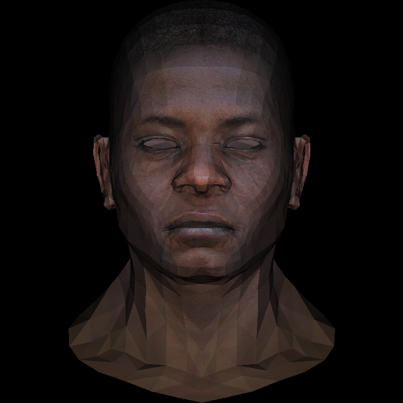
Meet, this is my friend z-buffer abstract African head. It will help us to remove the visual artifacts of discarding the back edges that we had in the previous article.
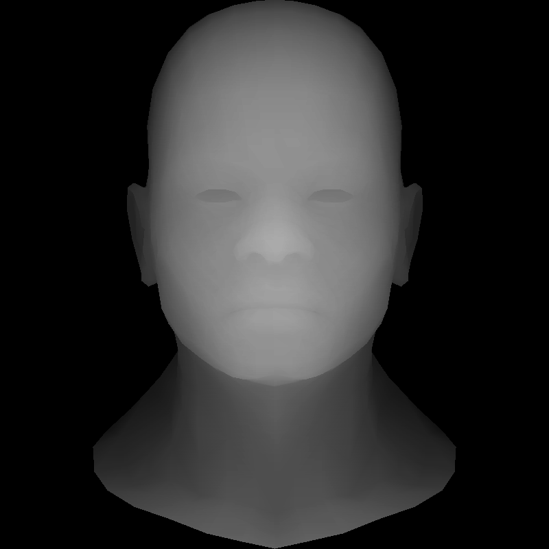
By the way, I can not fail to mention that this model, which I use in the tail and in the mane, was kindly provided by the wonderful Vidar Rapp .
We can use it exclusively as part of the rendering training. This is a very high-quality model, which I barbarously treated, but I promise to return her eyes!
In theory, you can not discard the invisible edges, but simply draw everything, starting from the very rear, and ending with the front.
This is called an artist algorithm . Unfortunately, it is very expensive, for each change in the position of the camera you need to re-sort the scene. And there are also dynamic scenes ... But even this is not the main problem. The problem is that this is not always possible.
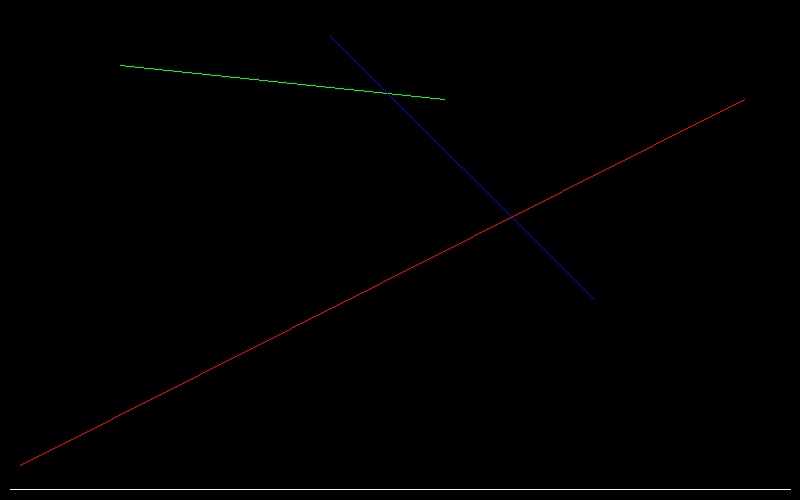
Before drawing the head, draw what is simpler
Let's imagine the simplest scene of three triangles, the camera looks down on top, we project our triangles on a white screen:
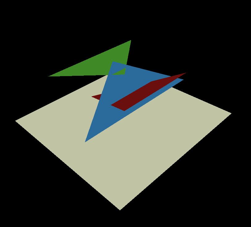
This is how the render of this scene should look like:

The blue side - is it red or in front? Neither this nor that. The artist's algorithm breaks down here. Well, that is, you can split the blue side into two, one part in front of the red one, the other behind. And the one that is in front of the red, another two - before the green and behind the green ... I think it is quite clear that in scenes with millions of triangles this quickly becomes a daunting task. Yes, it has solutions, for example, to use binary partitions of space , at the same time it helps to sort when changing the camera position, but let's not complicate our lives!
Three dimensions are too much. Y-buffer!
Let's lose one of the dimensions, consider a two-dimensional scene obtained by intersecting our scene and the yellow section plane:
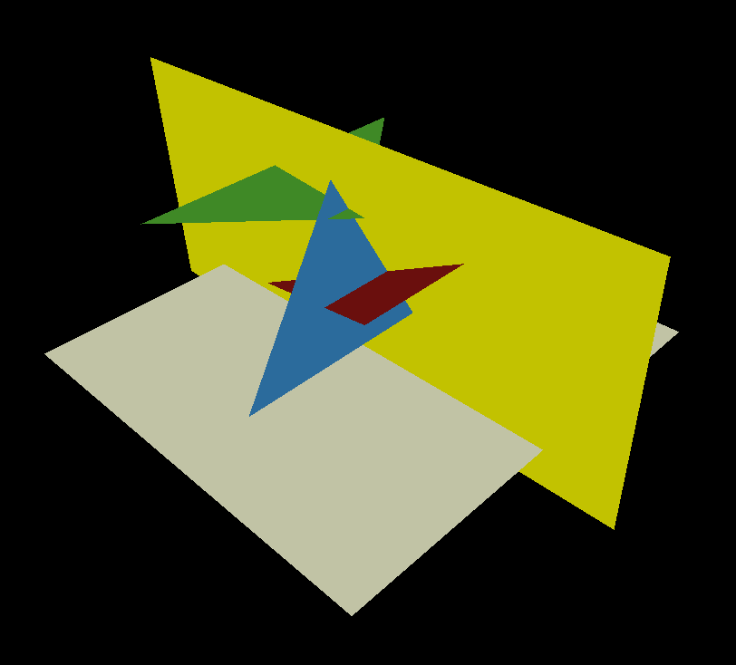
That is, our scene consists of three segments (the intersection of the yellow plane and each of the triangles), and its render is a picture
the same width as the normal render, but one pixel high:
A snapshot of the code, as usual, on a github. Since we have a two-dimensional scene, it is very easy to draw it, it's just three calls to the line () function, which we programmed for the very first time.
     {// just dumping the 2d scene (yay we have enough dimensions!)
         TGAImage scene (width, height, TGAImage :: RGB);

         // scene "2d mesh"
         line (Vec2i (20, 34), Vec2i (744, 400), scene, red);
         line (Vec2i (120, 434), Vec2i (444, 400), scene, green);
         line (Vec2i (330, 463), Vec2i (594, 200), scene, blue);

         // screen line
         line (Vec2i (10, 10), Vec2i (790, 10), scene, white);

         scene.flip_vertically ();  // i want to have the bottom corner
         scene.write_tga_file ("scene.tga");
     }
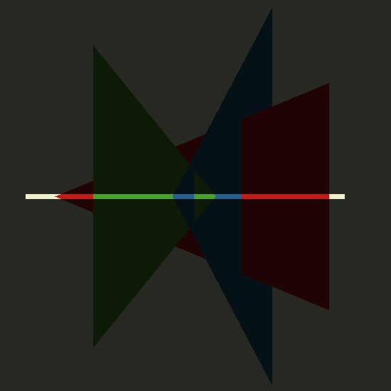
This is what our two-dimensional scene looks like; our task is to look at these segments from above.
Let's render it now. I remind you that the render is a picture that is one pixel wide for the whole scene and one pixel high. In my code, I declared it at a height of 16, but this is not to break my eyes, considering one pixel on high-resolution screens. The rasterize function only writes in the first line of the render image.
         TGAImage render (width, 16, TGAImage :: RGB);
         int ybuffer [width];
         for (int i = 0; i <width; i ++) {
             ybuffer [i] = std :: numeric_limits <int> :: min ();
         }
         rasterize (Vec2i (20, 34), Vec2i (744, 400), render, red, ybuffer);
         rasterize (Vec2i (120, 434), Vec2i (444, 400), render, green, ybuffer);
         rasterize (Vec2i (330, 463), Vec2i (594, 200), render, blue, ybuffer);
So, I declared the mysterious ybuffer array exactly the size of our screen (width, 1). This array is initialized minus infinity. Then I pass to the rasterize function both the render image, and this mysterious array. What does the function look like?
 void rasterize (Vec2i p0, Vec2i p1, TGAImage & image, TGAColor color, int ybuffer []) {
     if (p0.x> p1.x) {
         std :: swap (p0, p1);
     }
     for (int x = p0.x; x <= p1.x; x ++) {
         float t = (x-p0.x) / (float) (p1.x-p0.x);
         int y = p0.y * (1.-t) + p1.y * t;
         if (ybuffer [x] <y) {
             ybuffer [x] = y;
             image.set (x, 0, color);
         }
     }
 }
Very, very simple: I go through all the x-coordinates between p0.x and p1.x and calculate the corresponding y-coordinate of our line.
Then I check that we have in the ybuffer array on this x coordinate. If the current pixel is closer to the camera than what is stored there,
then I draw it in the picture, and put a new y-coordinate in the multi-buffer.
Let's understand in stages: after calling the rasterizer for the first (red) line, this is what we have in mind:
screen content:

y-buffer contents:

Here, in ugly purple, minus infinity is marked, these are the places where not a single pixel has been drawn yet.
Everything else is grayscale, because ybuffer is not a color, but the depth of a given pixel. The whiter, the closer to the camera was the pixel drawn on the screen.
Next we draw the green line, here is the memory after calling its rasterizer:
screen content:

y-buffer contents:

And finally, the blue:
screen content:

y-buffer contents:

Congratulations, we drew our two-dimensional scene! Once again we will admire the final render:

Three dimensions - this is just right. Z-buffer!
Snapshot of github code .
Attention: in this article I use the same version of the triangle rasterizer as in the previous one. An improved version of the rasterizer (the passage of all pixels of the describing rectangle) will soon be kindly provided and described in a separate article by a respected gbg ! Stay tuned.
Since our screen is now two-dimensional, the z-buffer should also be two-dimensional:
int * zbuffer = new int [width * height];
I packed a two-dimensional array in one-dimensional, you can convert as usual:
from two coordinates to one:
int idx = x + y * width;
Back:
 int x = idx% width;
 int y = idx / width;
Then in the code I go through all the triangles and make a call to the rasterizer, passing it both a picture and a z-buffer.
 triangle (screen_coords [0], screen_coords [1], screen_coords [2], image, TGAColor (intensity * 255, intensity * 255, intensity * 255, 255), zbuffer);

 [...]

 void triangle (Vec3i t0, Vec3i t1, Vec3i t2, TGAImage & image, TGAColor color, int * zbuffer) {
     if (t0.y == t1.y && t0.y == t2.y) return;  // i dont care about degenerate triangles
     if (t0.y> t1.y) std :: swap (t0, t1);
     if (t0.y> t2.y) std :: swap (t0, t2);
     if (t1.y> t2.y) std :: swap (t1, t2);
     int total_height = t2.y-t0.y;
     for (int i = 0; i <total_height; i ++) {
         bool second_half = i> t1.y-t0.y ||  t1.y == t0.y;
         int segment_height = second_half?  t2.y-t1.y: t1.y-t0.y;
         float alpha = (float) i / total_height;
         float beta = (float) (i- (second_half? t1.y-t0.y: 0)) / segment_height;  // be careful: here
         Vec3i A = t0 + Vec3f (t2-t0) * alpha;
         Vec3i B = second_half?  t1 + Vec3f (t2-t1) * beta: t0 + Vec3f (t1-t0) * beta;
         if (Ax> Bx) std :: swap (A, B);
         for (int j = Ax; j <= Bx; j ++) {
             float phi = Bx == Ax?  1.: (float) (jA.x) / (float) (Bx-Ax);
             Vec3i P = Vec3f (A) + Vec3f (BA) * phi;
             int idx = P.x + Py * width;
             if (zbuffer [idx] <Pz) {
                 zbuffer [idx] = Pz;
                 image.set (Px, Py, color);
             }
         }
     }
 }
It's just terrible how much the code looks like a rasterizer from the previous article. What changed? (Use vimdiff and see).
Vec2 was replaced by Vec3 in the function call and a check was made if (zbuffer [idx] <Pz);
Everything! Here is our real render without flaws cut off invisible surfaces:

Please note that backface culling in my code is left:
 if (intensity> 0) {
     triangle (screen_coords [0], screen_coords [1], screen_coords [2], image, TGAColor (intensity * 255, intensity * 255, intensity * 255, 255), zbuffer);
 }
It is not necessary to obtain this picture, it only accelerates the calculations.
Stop, we just interpolated the z-coordinate. And you can add something else to the load?
Textures! This will be homework.
In the .obj file there are lines vt uv, they define an array of texture coordinates.
The average number between slashes in fx / x / xx / x / xx / x / x is the texture coordinates of a given vertex in a given triangle. Interpolate them inside the triangle, multiply by the width-height of the texture file and get the color of the pixel from the texture file.
Diffuse texture take here .
Here is an example of what should happen:
Update:
Home solution is available here.
Source: https://habr.com/ru/post/248179/
All Articles