My experience in building 1-Wire industrial network
Prehistory
Like many habra users, possessing some skills and a good imagination, somehow came across the site, then he was still hanging on the people, and was dedicated to pairing home-made devices with a PC. It was then that the seed of impetuous interest was born to do something and manage it from a computer. Then, of course, it all started with a printer port lpt and gradually grew into a com port and eventually usb. All would be fine, until I came across the site, the dedication to create a smart home system. Then I realized that I was really interested. Let's skip a long and interesting story and go straight to the topic. I am writing this article as an amateur, not a pro, and I hope it will help you to create your own network from scratch, or to learn useful experience for your network. In the article I want to describe the creation of your 1wire network with zero, including all stages of construction and useful tips.- Designing, printing, etching, tinning and soldering a printed circuit board;
- Installation of industrial tires 1wire;
- Software and hardware management and monitoring.
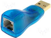 As you can see, one end is inserted into the usb port of the service system, it can be a computer or a wi-fi router, or unicameral solutions. The other end is the “mother” of the RJ-11 connector (standard telephone connector). I also use calibrated temperature sensors (DS18B20 +):
 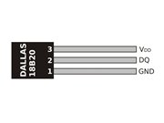 I also use and plan to use:
- Calibrated temperature sensors (DS18B20 +);
- 4-channel Analog-to-Digital Converters (DS2450S);
- 8-channel input / output chips (DS2408 +).
 VANIL-1853S (I did not use a board with 5 I / O and 3 triacs to connect high-voltage devices, so only through relays or magnetic starters, the range of applications is very wide):
 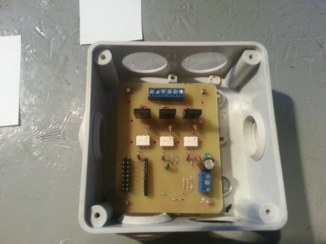 As you can see, everything is neatly placed in standard plastic sealed boxes with screws and hot melt glue. At the moment I use a network of only 20 thermal sensors, to monitor the temperature in the country, everything is connected to the server on Gentoo Linux. Software for working with a network of owfs. This first part of the article is intended for familiarization, the rest of the detailed information will be added later and at will of habouriors. I would also like to know your experience and listen to criticism. About etching boards: I switched from ferric chloride to salt + citric acid + hydrogen peroxide today. While there is no information on the quality of etching, the board is still being etched:
 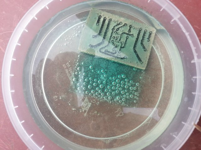 The composition is as follows: 100ml of peroxide, 30 grams of citric acid and 5-6 grams of table salt. And so after a while I want to add an article, and first of all I would say that I liked the new method of etching boards, a little longer, but the effect is not worse than from ferric chloride. I used to pay a board to control the level of liquid in a well with technical water, there are two sensors installed, one just above the nose, and the second at the top, there is also a semi-automatic control, manual start and stop, indicators in the form of light bulbs, talking about work system. Fluid level sensors are usually expensive, so I made them myself, unfortunately there is no opportunity to take pictures, they are already immersed in a well. But with pleasure I will describe the components and design.
 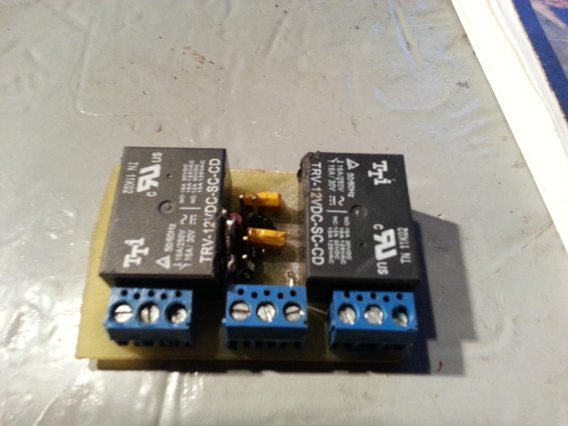 List of components used:
- Reed switch for metal doors, round, soldered interiors
- A piece of HDPE pipe about 10-15 cm
- Silicone, for roofing
- Rubber from the unsoldered box with a hole
- A piece of UTP wire, 4-wire (there was no less) of the required length
- Float material, I used polystyrene

 This system does not work with 1wire directly, you can only read the status of its work. What is actually enough, although simply connecting to one of the 8 I / Os, you can simulate the filling of the well and start pumping from the computer. Everything is mounted in a sealed box, including power supplies to the din rail
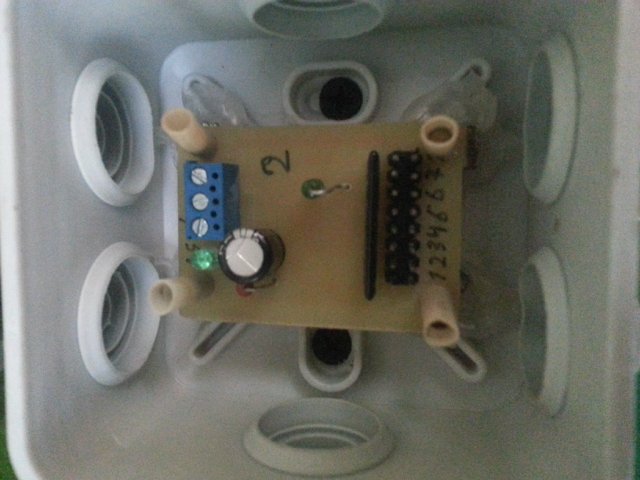
 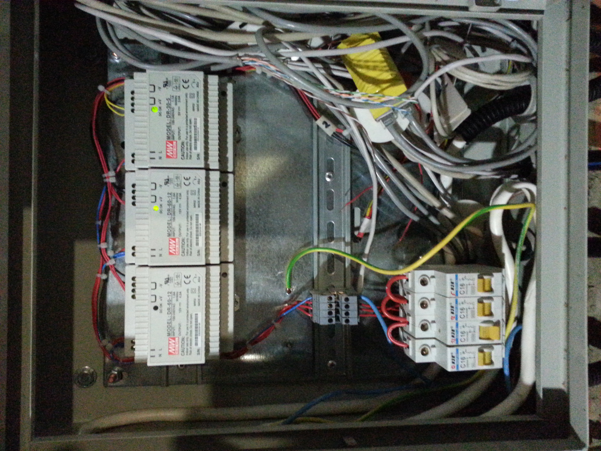 I also advise newbies to buy a debug board, it looks like this:
 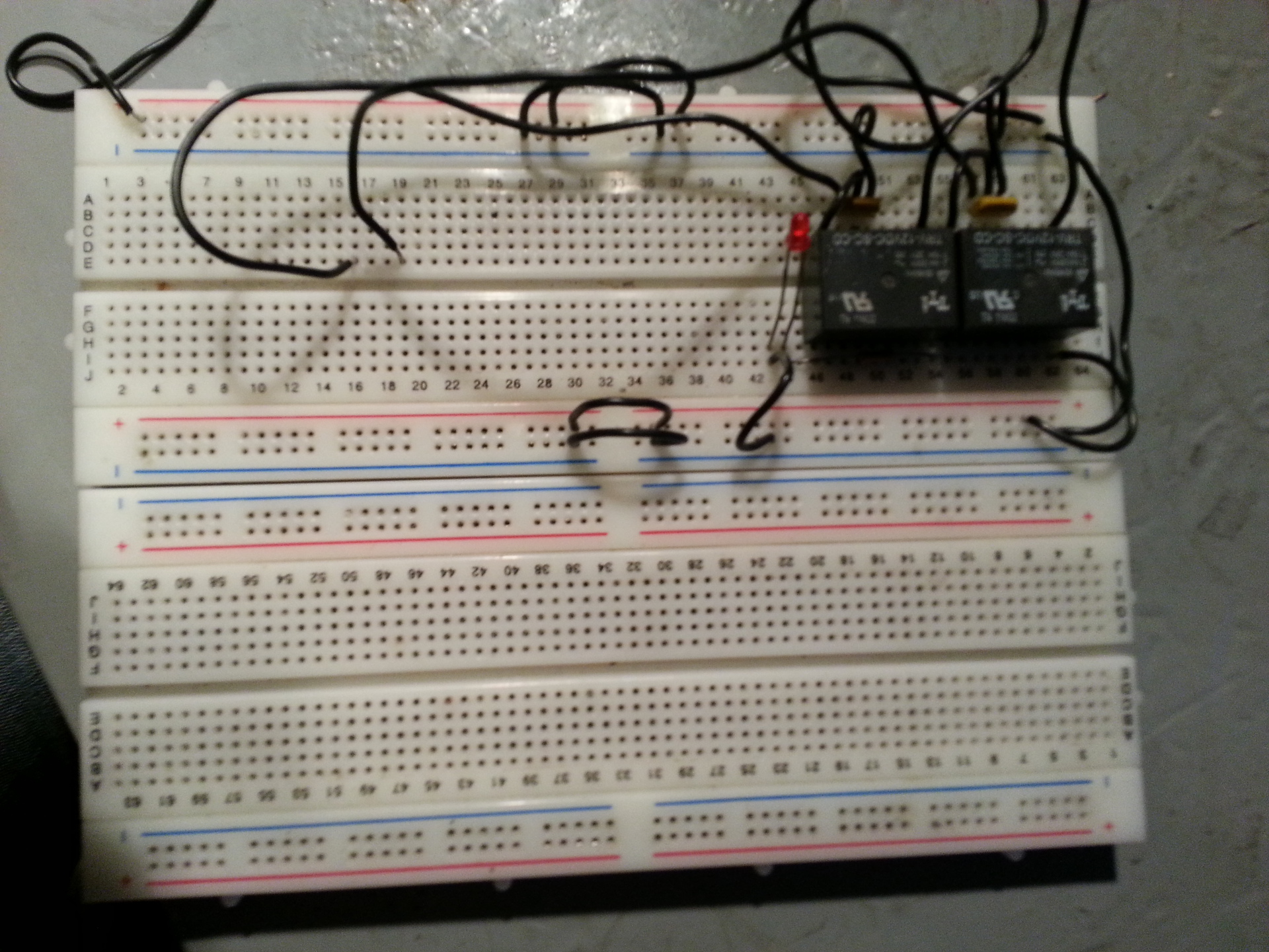 Here are the photos of the box:
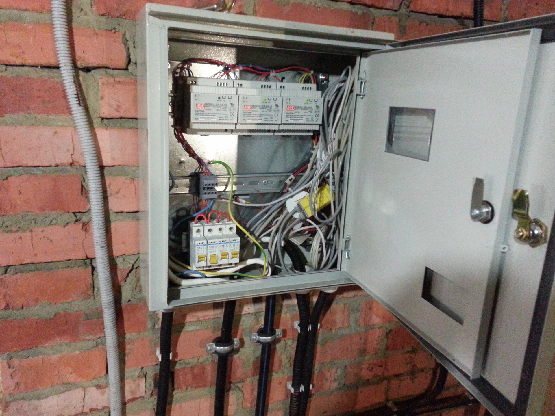
 I use the SLayer5 program to design the boards. The only thing I didn’t put all the PCB layouts here, as well as those that I hadn’t yet implemented. But this topic is not the final product, only my experience, and I am going to develop it. so the kernel had to build fuse to work with owfs, if you know Linux, then it will be easy for you to include a couple of new items when compiling the kernel. This is about the sofa. I scan the sensors every 15 minutes through CZK, then I draw the graphs by 4, that is, readings in an hour. Unfortunately, I can’t find anything in this article that I wanted, so I’ll write the rest in the next part, look for the 1wire tag
')
Source: https://habr.com/ru/post/238501/
All Articles