And let me tell you about the gradients!
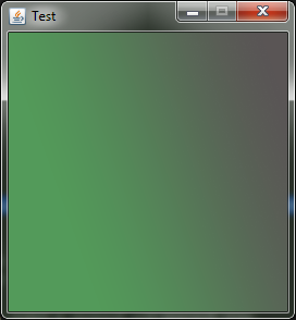
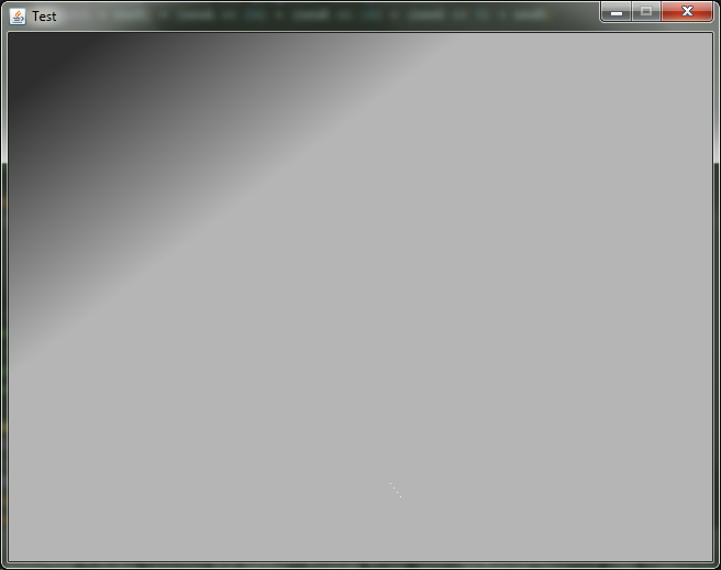
final result screen
In this article, I talk about how I invented my own personal bicycle, which draws a gradient almost like in Photoshop. Immediately I warn you, the algorithm is terribly slow and unoptimized. Optimization and consideration of some popular gradient algorithm I'm going to do in the second part of the article.
What for?
Somehow I wanted to implement software rendering of gradients that are most similar to Photoshop. I had no specific goal, so an interesting task for the evening. Java was selected as the language. The important idea was that I wanted to write this algorithm on my own, without peeping into other algorithms.
')
What should have happened
The drawGradient () method should work as follows: we set the coordinates and colors of the two points, after which a gradient is drawn over the entire image. Like that:
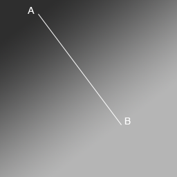
In this figure, point A has coordinates (55; 20) and color 0xff2e2e2e, and point B has coordinates (175; 180) and color 0xffb5b5b5. do not forget that the origin is in the upper left corner, and the Y axis is directed downwards.
We start to understand
As a reference, I took the gradient from Photoshop from the last screenshot. As you can see, the gradient consists of three parts:
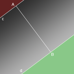
The red part should be filled with the color of point A, the green part should be point B, and the color of each pixel of the remaining area should be calculated depending on the distance from it to the straight lines c and d.
I think it is obvious that we need an algorithm that will determine the distance from any pixel to the straight lines c and d. You also need a way to determine which pixel is in the “red” area, which is in the “green” area, and which is in the remaining area.
Recall a school course in geometry and draw the following illustration for a random pixel E:
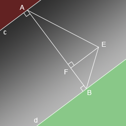
In this figure, AF is the distance from pixel E to line a. And, accordingly, FB is the distance to the straight line b. It is these distances that will determine the color of the pixel. And then the problem is solved with determining which area the pixel belongs to. It's all very simple. If AF + FB> AB, then the pixel is either in the red or in the green zone. To determine which one, let's compare AF and FB. If AF> FB, then the pixel is in the green zone, otherwise in the red. Here is a math.
So, our task is to find AF and BF. Let's concentrate on AF, according to the Pythagorean theorem, it turns out that:

So, we can learn the square of length AE from the same Pythagorean theorem, since we know the coordinates of points A and E. It turns out like this:

It remains to find only EF. This is a little more difficult, but nothing terrible. Since our segment EF is the height of the triangle, dropped on the side AB, the formula for finding the height will help us. It looks like this:

And p is one of the most misleading things. This is not a perimeter, but a semi-perimeter. I remember a couple of times made in the school file on this occasion. It is considered as:

AB and EB are calculated in the same way as AE - based on the coordinates.
So, the AF counting algorithm is in full view:
1. Calculate AE, EB and AB
2. Calculate p
3. Calculate EF
4. We calculate AF
The algorithm for BF is similar, I will not paint it.
It's time to go!
I decided to create a class that represents a wrapper for a BufferedImage, let's call it EditableImage. And in this class, in my estimation, the following methods should have been:
EditableImage(int width, int height); // void clear(int color); // void drawGradient(int x1, int y1, int color1, int x2, int y2, int color2); // BufferedImage getImage(); // Hereinafter, all the colors in my code are given as int, which has the following form:
0xAARRGGBB AA - ( 32 ) RR - GG - BB - The idea with the class is convenient because if I later want to implement some more chips besides the gradient, it will be easy to do.
Let's start with auxiliary pieces that are irrelevant to the gradient
Gradient.java - program entry point
package ru.idgdima.gradient; import javax.swing.*; public class Gradient { public static final int IMG_WIDTH = 640; public static final int IMG_HEIGHT = 480; private static GradientPanel panel; //, public static void main(String[] args) { // , // JFrame frame = new JFrame("Test"); frame.setDefaultCloseOperation(WindowConstants.EXIT_ON_CLOSE); frame.setResizable(false); // , , // , // panel = new GradientPanel(IMG_WIDTH, IMG_HEIGHT); frame.add(panel); frame.pack(); frame.setLocationRelativeTo(null); frame.setVisible(true); } } GradientPanel.java - the panel on which the gradient will be displayed
package ru.idgdima.gradient; import javax.swing.*; import java.awt.*; import java.awt.image.BufferedImage; public class GradientPanel extends JPanel { private BufferedImage image; public GradientPanel(int width, int height) { // super(); setPreferredSize(new Dimension(width, height)); // , , // BufferedImage // EditableImage gradientImage = new EditableImage(width, height); gradientImage.clear(0xff000000); gradientImage.drawGradient(55, 20, 0xff2e2e2e, 175, 180, 0xffb5b5b5); image = gradientImage.getImage(); } @Override protected void paintComponent(Graphics g) { super.paintComponent(g); // . // : g.drawImage(image, 0, 0, null); } } EditableImage.java - The most interesting class, the method for the gradient is empty for now.
package ru.idgdima.gradient; import java.awt.image.BufferedImage; public class EditableImage { private int width; private int height; private int[] rgb; // BufferedImage image; // getImage public EditableImage(int width, int height) { this.width = width; this.height = height; rgb = new int[width * height]; // // getImage image = new BufferedImage(width, height, BufferedImage.TYPE_4BYTE_ABGR); } /** * * @param color */ public void clear(int color) { for (int i = 0; i < rgb.length; i++) { rgb[i] = color; } } /** * * @return */ public BufferedImage getImage() { // rgb image image.setRGB(0, 0, width, height, rgb, 0, width); return image; } public void drawGradient(int x1, int y1, int color1, int x2, int y2, int color2) { // } } This program can be compiled already at this stage, but it will show us just a black image. It's time to write a method for the gradient!
I did it like this:
drawGradient
public void drawGradient(int x1, int y1, int color1, int x2, int y2, int color2) { float dx = x1 - x2; // float dy = y1 - y2; float AB = (float) Math.sqrt(dx * dx + dy * dy); // // for (int y = 0; y < height; y++) { for (int x = 0; x < width; x++) { dx = x1 - x; dy = y1 - y; float AE2 = dx * dx + dy * dy; float AE = (float) Math.sqrt(AE2); dx = x2 - x; dy = y2 - y; float EB2 = dx * dx + dy * dy; float EB = (float) Math.sqrt(EB2); float p = (AB + AE + EB) / 2f; float EF = 2 / AB * (float)Math.sqrt(Math.abs(p * (p - AB) * (p - AE) * (p - EB))) float EF2 = EF * EF; float AF = (float) Math.sqrt(Math.abs(AE2 - EF2)); float BF = (float) Math.sqrt(Math.abs(EB2 - EF2)); if (AF + BF - 0.1f > AB) { // rgb[y * width + x] = AF < BF ? color1 : color2; } else { // float progress = AF / AB; // interpolate rgb[y * width + x] = interpolate(color1, color2, progress); } } } } /** * @param num - * @return 0, num < 0; 255, num > 255; num */ private static int clip(int num) { return num <= 0 ? 0 : (num >= 255 ? 255 : num); } Please note that I use the module function - Math.abs () wherever there is even the slightest probability that a negative number can get into the function of finding the square root - Math.sqrt (). Otherwise, we will have artifacts.
And in this line, if you remove
- 0.1f , it turns out just a terrible mess. Due to the error of calculations, we have to take a small number: if (AF + BF - 0.1f > AB) { It remains only to deal with the interpolate method and the trick is done. It should take the initial color, the final color and the number of progress, which can be from 0 to 1 and which determines the proportion of each color. For example, if progress = 0, the initial color is returned, if progress = 1 the final color, and if progress = 0.5, the average color between the initial and final color. The task is clear, the method is written:
interpolate
private int interpolate(int color1, int color2, float progress) { // int a1 = (color1 & 0xff000000) >>> 24; int r1 = (color1 & 0x00ff0000) >>> 16; int g1 = (color1 & 0x0000ff00) >>> 8; int b1 = color1 & 0x000000ff; int a2 = (color2 & 0xff000000) >>> 24; int r2 = (color2 & 0x00ff0000) >>> 16; int g2 = (color2 & 0x0000ff00) >>> 8; int b2 = color2 & 0x000000ff; // float progress2 = (1 - progress); int newA = clip((int) (a1 * progress2 + a2 * progress)); int newR = clip((int) (r1 * progress2 + r2 * progress)); int newG = clip((int) (g1 * progress2 + g2 * progress)); int newB = clip((int) (b1 * progress2 + b2 * progress)); // return (newA << 24) + (newR << 16) + (newG << 8) + newB; } Let's look at the result!
Already not bad, but ours uses linear interpolation, and in Photoshop there is definitely some other move.
About interpolation
Look carefully at the picture. The left gradient is drawn by our algorithm, the right one by photoshop. Each line has a red dot. And the darker the line, the dot to the left:
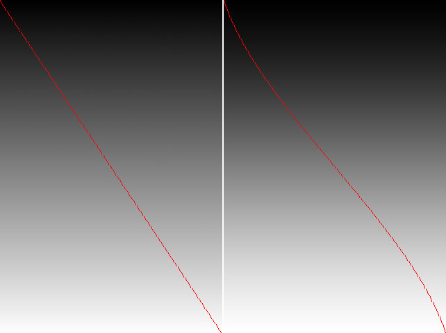
As you can see, our line is straight, like a rail. It is necessary to fix it. Here I did not come up with anything sensible and decided to peep on the Internet. Found an article on Habré, which describes some types of interpolation, and even the code is: habrahabr.ru/post/142592
Well, we realize cosine interpolation! First, add two constants to the EditableImage class:
public static final int INTERPOLATION_LINEAR = 0; public static final int INTERPOLATION_COS = 1; Second, we will rewrite the interpolate method a bit, so that one of these constants is supplied to it at the input:
Hidden text
private int interpolate(int color1, int color2, float progress, int interpolation) { // int a1 = (color1 & 0xff000000) >>> 24; int r1 = (color1 & 0x00ff0000) >>> 16; int g1 = (color1 & 0x0000ff00) >>> 8; int b1 = color1 & 0x000000ff; int a2 = (color2 & 0xff000000) >>> 24; int r2 = (color2 & 0x00ff0000) >>> 16; int g2 = (color2 & 0x0000ff00) >>> 8; int b2 = color2 & 0x000000ff; // float f; if (interpolation == INTERPOLATION_LINEAR) { f = progress; } else if (interpolation == INTERPOLATION_COS) { float ft = progress * 3.1415927f; f = (1 - (float) Math.cos(ft)) * 0.5f; } else { throw new IllegalArgumentException(); } int newA = clip((int) (a1 * (1 - f) + a2 * f)); int newR = clip((int) (r1 * (1 - f) + r2 * f)); int newG = clip((int) (g1 * (1 - f) + g2 * f)); int newB = clip((int) (b1 * (1 - f) + b2 * f)); // return (newA << 24) + (newR << 16) + (newG << 8) + newB; } Then add
int interpolation to the list of parameters of the drawGradient method and add this variable to the line calling the interpolate method: rgb[y * width + x] = interpolate(color1, color2, progress , interpolation); Finally, in the GradientPanel class, we rewrite the call to the drawGradient method, adding INTERPOLATION_COS to it
This is what happened with this interpolation method:
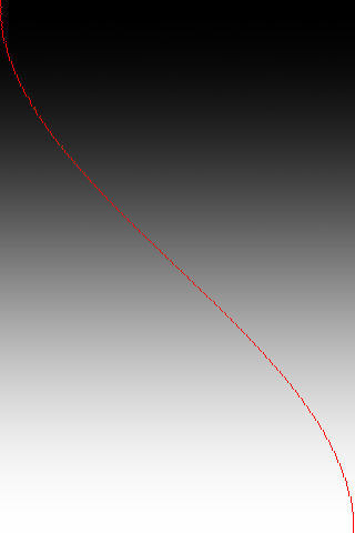
Hmm, it looks good, but in Photoshop the line is clearly not that curve. What to do? That is too straight, then too curve ... And what if we make the average of these two extremes?
Great idea, add constant
INTERPOLATION_COS_LINEAR = 2And in the code of the interpolate method we add one more else if:
} else if (interpolation == INTERPOLATION_COS_LINEAR) { float ft = progress * 3.1415927f; f = (progress + (1 - (float) Math.cos(ft)) * 0.5f) / 2f; } And lo and behold, it turned out almost a complete copy of the gradient from Photoshop!
See for yourself:
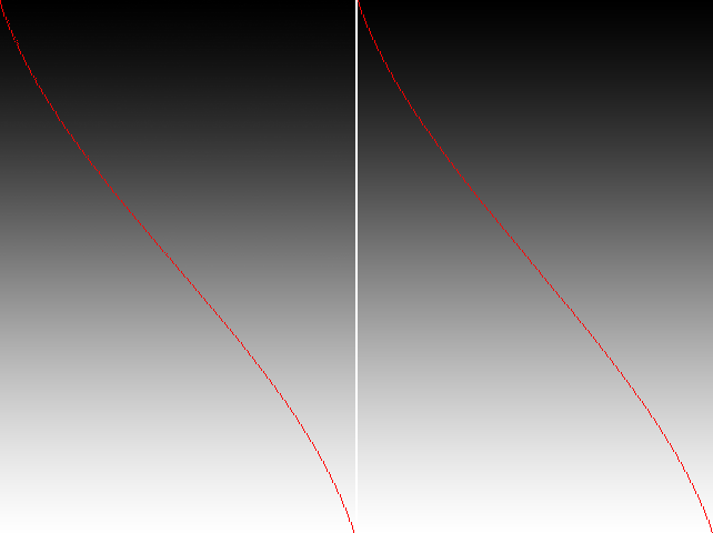
Our left.
But you two pictures from the top screenshot, combined into one. It is seen that the interpolation is almost the same, the differences can be blamed on errors when rounding:
Hurray, we made a gradient like in photoshop, albeit much slower.
Sources and jar
On this I finish the first part. In the second part I will try to optimize the algorithm as cool as I can. And I implement some ready-known fast gradient drawing algorithm, and then compare it in speed with my own.
By the way, if you have in mind fast gradient drawing algorithms, leave them in the comments.
Source: https://habr.com/ru/post/180839/
All Articles