Mustached shooter with a polygonal belly. Part two
The story about the development of the project is similar to the web: everywhere there are threads of associations, stories about interesting ideas. And sometimes the threads of the story wrapped in a cocoon around an unusual bug. And now, the material has accumulated so much that you have to start working on the second part of the article before the first one is published.
And now, when the second part is published, there is enough material for the third part! :)
Today in the program: a mixture of visual and architecture of the project. But first, a couple more details about the shadows.
So let's go!
Articles
- First part. Mustached shooter of twenty-three polygons.
- The second part of. Mustached shooter with a polygonal belly.
Table of contents
- Shadow manager
- Architecture Refactoring
- Refactoring game objects
- Death effect
- Stain effect
- Tile rendering
- The conclusion of the second part
 Level 3.4. Shadow Manager.
As you remember, shadows are already generated on the CPU with a bunch of optimizations. But their drawing needs to be improved. While I was dealing with generation, I needed the simplest rendering method, so everything works like this:
- Each object casting a shadow has two children, which render shadows with different shaders (one is back only - faces, the other is front);
- On the stage is a huge sprite, which is drawn the latest, and tinted in the desired color, if the stencil non-zero value.
- The simplest is duplication of objects (two identical descendants of each element). Getting rid of them by making a two-pass shader is not an option, since Objects with multipass shaders do not know how to batch;
- Further, the ability to make only one light source with shadows;
- Very meager opportunities for working with light (because in fact, there is no light, only a shadow). So you can make a color shade, but color lighting does not;
- Stencil buffer is occupied entirely and cannot be used for other effects.
The idea is simple: render the shadow rendering in a separate passage, adding the ability to cast shadows to any number of light sources (yes, fps will sag).
In total, several classes were required:
- LightSource , a flashlight with an infinite range, adjusting the colors of the shadow and lighting;
- IShadowSource , an interface with a shadow conversion function void RebuildShadow (Vector3 lightPosition);
- ShadowRenderer , which registers all sources of light and shadows and is able to render shadows.
The code is written, shaders are checked, you can move on. And then the problems started.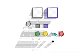
Faded shadows.
The image above has two problems.
First, the shadows are too long and sometimes incorrectly overlap objects. This may be if the shadows are rendered on top of an empty z-buffer (other objects may overlap the shadow, but the shadows themselves do not write anything in z-buffer).
Secondly, the shadows in some strange noise. This happens if you work with an uncleaned buffer.
So, the problem is that the z-buffer with which I work, apparently, was not used by the camera. Frame rendering now works like this:
- Rendering a scene in RenderTexture;
- Shadow rendering, depth-buffer is taken from item 1, and color-buffer is yours (more on this below);
- Compositing shadows and rendered scenes;
- Post effects
When working with post-effects it is often necessary to transform a texture using some kind of shader. In Unity3D, there is a Graphics.Blit method for this. We pass the original texture to it, specify the target - where to draw, the material and even the passage of the shader.
In fact, we work with at least three different buffers:
- The original color buffer, from where we read the colors of the pixels;
- The target color buffer where we write the colors;
- Depth + stencil buffer to which we write (and from which we read the depth and data of stencil).
And in the Graphics.Blit method, the target color buffer and depth buffer are inseparable. That is, if we need, for example, to read the depth of the scene's geometry from the source texture, and write pixels to the target texture, a bummer.
Or if we rendered the scene into texture, part of the shaders have written the data to the stencil, and now we want to get a new texture, using this data (and retaining the original texture!) - also a bummer.
There is a solution in the Unity3D documentation about this explicitly stated:
If you want to use the same texture as the depth of the texture, it is possible to use it. (GL.LoadOrtho), setup material pass (Material.SetPass) and draw a quad (GL.Begin).
In general, a modified version of Blit, which allows to separate the transfer of buffers:
static void Blit(RenderBuffer colorBuffer, RenderBuffer depthBuffer, Material material) { Graphics.SetRenderTarget(colorBuffer, depthBuffer); GL.PushMatrix(); GL.LoadOrtho(); for (int i = 0, passCount = material.passCount; i < passCount; ++i) { material.SetPass(i); GL.Begin(GL.QUADS); GL.TexCoord(new Vector3(0, 0, 0)); GL.Vertex3(0, 0, 0); GL.TexCoord(new Vector3(0, 1, 0)); GL.Vertex3(0, 1, 0); GL.TexCoord(new Vector3(1, 1, 0)); GL.Vertex3(1, 1, 0); GL.TexCoord(new Vector3(1, 0, 0)); GL.Vertex3(1, 0, 0); GL.End(); } GL.PopMatrix(); Graphics.SetRenderTarget(null); } Use in code:
void RenderShadowEffect(RenderTexture source, RenderTexture target, LightSource light) { shadowEffect.SetColor("_ShadowColor", light.ShadowColor); shadowEffect.SetColor("_LightColor", light.LightColor); shadowEffect.SetTexture("_WorldTexture", source); shadowEffect.SetTexture("_ShadowedTexture", target); Blit(target.colorBuffer, source.depthBuffer, shadowEffect); } So what is the matter? Why is my RenderTexture, in which I render the camera on the output completely empty (and not even cleared of garbage)?
Turn off the shadows and see what the frame debug shows:


Strange render textures.
Curious. Apparently, the post-anti-aliasing effect forces the camera to render into its texture. At the same time, I don’t have access to this texture: when debugging in Camera.activeTexture is empty.
Ah, so, antialiasing! Climb into my drawing sequence? Then I will get into your code!
The post effects work through the MonoBehaviour.OnRenderImage method, and I through the MonoBehaviour.OnRenderImage and
MonoBehaviour.OnPostRender . I make a dirty hack: rename OnRenderImage to Apply and call it with my hands, after rendering the shadows, with my renderTexture. Now antialiasing does not interfere with shadows.
New shadows allow you to make funny, but not very necessary things like chromatic aberration or smooth shadows.
Hundreds of ordinary pale shadows with a slight offset.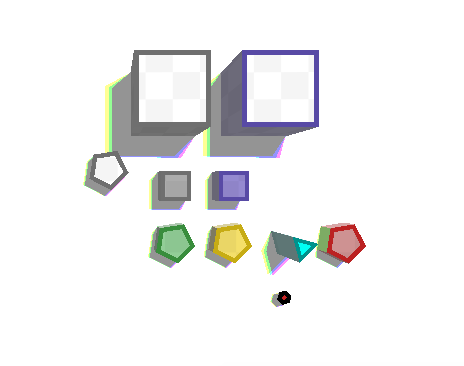
Three colored shadows.
While the shadows slow down on mobile phones (eat about 10 - 15 extra fps). If everything is sad, at the end I will translate everything into single-pass rendering, but for now I will not lean on light sources.
Hint: improvise in debugging graphics! Debugging vertex shaders can be painful, so visualize all the data you can: pull vertices along the normals, add color and transparency, etc.
Debash visualization through shaders and gizmos.

It turned out that adding new classes became harder due to some unsuccessful design decisions.
Todo: clean the architecture and code of the project
 Level 4.1. Refactoring architecture.
As you remember, I am developing a project with a prototype. But you don’t want to pull all the prototype architecture (do you know which architecture in the prototypes written in 2 hours?), So you need to refactor.
So:
First of all, I am putting as much data as possible from MonoBehaviour to ScriptableObject . This is all sorts of styles, settings, library prefabov;
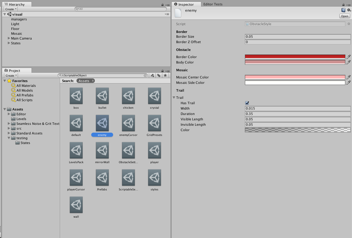
Project Settings.
I break all logic into small classes, for example, BulletCaster or MovableObject . Each of them contains the necessary settings and pursues only one goal.
public class BulletCaster : MonoBehaviour { public void CastBullet(Vector2 direction); } public class MovingBody : MonoBehaviour { public Vector2 Direction {get; set;} public bool IsStopped {get; set;} } 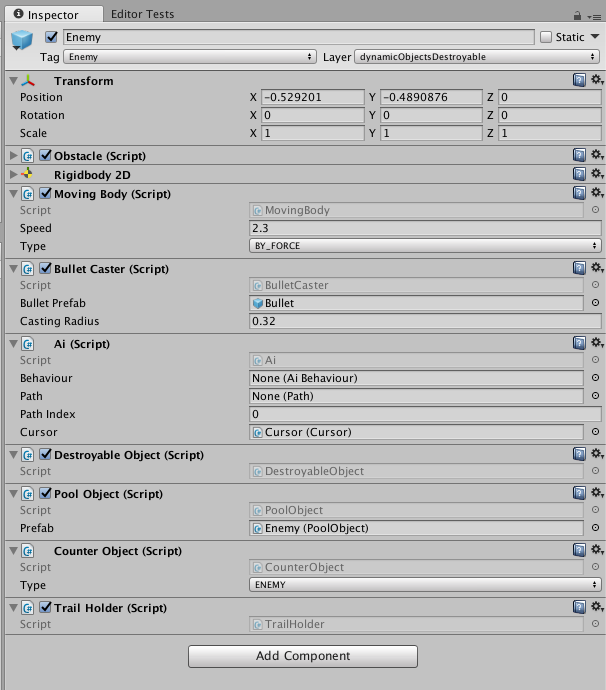
From microclasses you can collect complex logic.
I remove direct dependencies on singletons (Clock, ShadowManager, etc.) and implement the service locator pattern (a somewhat controversial thing, but far more accurate than scattering singletons).
I implement collision processing through layers, optimizing them, clearly removing impossible collisions (for example, static <-> static).
I optimize the creation of objects by writing a global pool. I think this is another bike, but I wanted to write it with my own hands. The pool is able to create objects by prefab key, initialize them after creation, notify objects about creation / deletion.
My bullets have a life time limit (about 10 seconds of unfrozen time). A strange bug appeared once: some of the bullets disappeared right in the air, as if the cooldown was advancing ahead of time and the bullet disappeared on a timer.
It was difficult to catch: not all the bullets disappeared, and debazhit each, hoping that at least one will disappear - very tiring.
However, we managed to find out two strange facts:
- The bullets began to disappear only after the level was restarted;
- The code responsible for removing bullets was not called at all.
The most important rule once again did not let down:
The stranger the bug seems, the more stupid its causes.
So enjoy:
- Levels are recreated on the same stage, without rebooting;
- When creating a level, I forgot to delete old walls (because the level is the same, it was not visible anywhere except in the hierarchy;
- When the bullet touched such a double wall, the collision handler was called twice;
- In the collision handler, the bullet is removed (added to the pool). Thus, in the pool data there were two references to the same bullet;
- After some time, the player fired this bullet;
- When trying to shoot again from the pool, a link was taken to the already active, flying bullet. She reinitialized, changed her coordinates and the “previous” bullet disappeared right in the air.
Of course, such a mistake could be without the old walls, with complex collisions. Therefore, I added checks for object activity during collisions and, of course, began to remove old walls.
I recall the problem with the uncomfortable touch and implement TouchManager. He remembers the last touch and tracks only his. It keeps the last N movements, ignoring too short ones (finger trembling). At the moment when the finger or the mouse stopped touching the screen, the manager calculates the direction and length of the gesture. If the gesture is too short - the manager ignores it: the player changed his mind, without choosing a clear direction.
Now the code has become more readable, adding new classes has become easier, and the feeling that the architecture of the project will collapse when adding the latest feature before the release has disappeared.
You can return to art and game logic. In truth, the logic of the game would do well to clean up.
Todo: think about the gameplay elements, clarity and simplicity of the gameplay for the player.
 Level 4.2. Refactoring game objects
When I was thinking about the gameplay features, I was fascinated by the huge amount of possibilities. Judge for yourself, all objects can have four orthogonal characteristics:
- Does the bullets reflect or absorb them?
- Will we destroy the object with a bullet?
- Is it moving or static?
- What is the type of object (player / enemy / civil)?
All these characteristics can be combined and even changed on the fly. But how to show it to the player? At first my list of objects looked like this:
- Ordinary walls . Absorb the bullets;
- Mirror walls . Reflect bullets;
- High-rise walls . Each floor is plain or mirror. When a bullet hits the ground floor is destroyed, the top fall down. So you can do counters, etc .;
- The boxes . Dynamic, but indestructible, absorb bullets;
- Mirror boxes . Dynamic, but indestructible, reflect bullets .;
- Chickens Dynamic, destructible, the player loses points when they die;
- Enemies . Dynamic, destructible, you need to defeat all to pass the level;
- Mirror enemies . Ordinary enemies, but the bullet, destroying the enemy, is reflected;
- Crystals Dynamic, destroyed by a bullet, if a player touches them, he gets a bonus;
- Player

All available objects.
I will obviously have problems with clear visualization of all this beauty. When I started working on a low-poly version, I planned to use simple color coding:
- The color of the edge determines the type of object;
- The white color of the ceiling indicates a static object (wall), the ceiling tinted in the edge color is dynamic.
For example, a gray edge means that the object will absorb a bullet, purple - will reflect. But it turns out that the color of the edge must encode a lot of properties. Too hard. I find the types of objects with obvious problems:
- High-rise walls. When only one floor remains, it will not differ from a regular wall. But he will be destroyed. Or not? Very illogical feature;
- Mirror boxes. The bullet always moves at the same speed. Reframe from the boxes, it will accelerate them endlessly and unpredictably;
- Mirror enemies. We'll have to use a different color, not like either the "enemy" or the "mirror". This entity only confuses all the cards.
Total remains:
- Two types of walls, ordinary and mirror;
- Player;
- Chickens;
- Enemies;
- Crystals;
- The boxes.

Objects remaining after cleaning.
Everything is well coded with color, there are few objects, but there is room for level design.
Now, when I decided on the game entities and cleaned the code from garbage, you can bring the graphics to the final state. These are effects and physics, and all sorts of interface elements. In short, a lot of work.
Todo: start developing release effects.
 Level 5.1. The effect of death.
The exact, verified gesture and move is made. The bullet flies, is reflected from the wall, passes in a few pixels from the player, touches the edge of another reflector and again changes direction. Now it is aimed at the last opponent on the map. The move is over. New move, waiting for victory. The direction is no longer important: the past bullet will do its job. So, the laws of geometry are relentless and the projectile finds its goal. The bullet touches the enemy ... And the enemy just disappears. Here is a bummer.
Yes, I want some fan when hit by a bullet. To the game visually said:
- "Yes, man, you did it! You figure it out in hell grandmother!"
Or vice versa: - "Careful, careful ... Noooo! You were so close, and now you have to go through everything again!"
But now when the bullet hits, the elements simply disappear. I try to make a smooth immersion of objects through the floor. It looks slow and unnatural, and yet, it is not clear that the object has already been destroyed and it is impossible to interact with it.
Okay, what is required of the effect of doom?
- It should be bright, tangible and meaningful;
- The consequences of death must be visible throughout the entire level, helping to plan for the passage, but not distracting.
Splinters! Let the bullet breaks opponents into pieces! Hmm, is it not difficult? Nope, all objects are convex, and cutting convex polygons is a pleasure.
In fact, I just can’t cut the enemy in half. It consists of several meshes:
- The inner part, a convex polygon, everything is simple;
- Color ring. It is not only not convex, and even with a hole. But it consists of N (where N is the number of sides) of convex quadrilaterals. So just save them in an array and cut each of them;
- Outer side. In fact, this is the outer side of the quadrilaterals from the previous paragraph. But I will work with it as with a large convex polygon - for rendering side faces and physics through PolygonCollider2D.

Parts of the object that need to be cut separately.
As a result, the algorithm is as follows:
- I transform an object (player, enemy, etc.) into the inside, an array of pieces of the ring, the outside. In the future I will call this structure "Piece";
- I find the geometric center for the Piece;
- I choose a random direction and “lead” a straight line in this direction through the geometric center;
- Piece cut this straight. To do this, take each polygon of the Piece (ring, inner and outer parts or their pieces):
4.1. I create the left and right array of points;
4.2. I specify the current array - left ;
4.3. I add the first point of the polygon to the current array;
4.4. I go through all the remaining points;
4.5. If the current and previous points are on the same side of a straight line, add the current point to the current array;
4.5. If the current and previous points are from different sides of the line, I find the intersection point, add it to both the left and right arrays. I switch the current array to the opposite. I add the current point to the new current array. - I add all the left shards to the new left Piece, and the right to the right ;
- Dream cut the resulting fragments recursively, to the specified depth.
With each cut, I divide the objects into two parts, so with three cuts, 8 fragments are obtained. It would be possible to "play" a little with depth, but also so beautiful.
I modify the creation code of the mesh, the collider and the shadow of the polygon so that it can also create fragments at specified points.
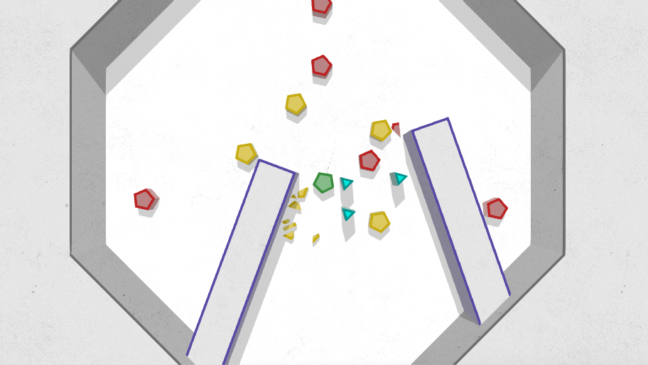
I get about such fragments.
At first, I planned to make cached partitions and use only them, but it turned out that real-time splitting does not cause brakes, but looks more effective.
The fragments revealed a nasty bug with shadows: I looked for the silhouette points on the polygons incorrectly. Because of this, in the previous video, part of the fragments cast shadows only partially. Corrections are already available in the previous article.
So, now when a bullet hits a target, I replace the latter with shards. The object is removed to the pool, and the fragments are loaded from the pool and update their meshes / colliders according to their new form. The velocities for rigidBody are calculated based on the speed of the destroyed element and the direction of the bullet. The splinters are off the isBullet flag, they only interact with the walls and with each other. Each fragment has a special class FloorHider, it lowers the object along the z coordinate through the floor, and after its complete disappearance, it deletes (moves to the pool.)
A small retrospective:
- Shards - very "physically" understandable image. Therefore, it helps to understand the concept of stopping time. Shards begin to scatter, then time stops and everything stops. The game stopped looking deterministic step by step;
- All the fragments are trapped with each other and do not inhibit;
- The crystal is now removed when touched with no effects. Maybe also break into pieces?
- There is not enough of a trace after the destruction, I want to keep the level of the consequences of the attacks;
- Fano looks, I want to shoot!
Splinters!
Enemies scattering into pieces is a very effective touch, but it is spoiled by the fact that the fragments disappear without any trace. There are several reasons, besides showiness, why should I add these traces.
Todo: realize the effect of splinter marks.
 Level 5.2.1. The effect of stains.
When I was thinking about a visual, the idea of "blood stains" spun in my head, which would appear if a player or npc died. On long levels, such spots will become convenient labels for navigation. And in case of loss, they will help to assess the initial position of the enemies and think about the tactics of re-passing.
So the spots. I discard the option with decals and rendered textures: it seems to me that this is how I will get out of style. I try to display the trace of the fragments or the place of their disappearance. It looks bad:


Different varieties of spots.
I think about a full fill, among the options I prototype this:
Just creating heaps of triangles.
Yes, I liked this option more. But creating lots of triangles with wild overdraw is a bad idea. However, the result is similar to a mosaic, so I think in the direction of the Voronoi diagram.
That's just generate it on the fly, especially with the subsequent relaxation of Lloyd (relaxation makes the cells similar in size) on mobile devices will be too painful. Prejudice is needed. And hence another problem: the spots can be at any distance from each other, and I, obviously, cannot predict an infinitely large diagram. Do you know what tiling is? :)
For a start, I find a suitable library for generating a Voronoi diagram.
Now I understand tiling. It would be an ideal solution to build a diagram directly on a torus, but you really don't want to go into the jungle of the library or even write your own. Therefore, I come up with the following algorithm:
- I create N points in a square with coordinates {-0.5, -0.5, 0.5, 0.5};
- For each Y in the interval [-tiles, tiles] and X in the interval [-tiles, tiles], except for X = 0, Y = 0:
2.1. I copy the points with the X, Y offset (at tiles = 1, I get 9 tiles with my initial one in the center); - I build a Voronoi diagram over all points (including offset clones);
- I apply, if necessary, the relaxation of Lloyd;
- I go through all the resulting polygons and leave only those whose center is in the source square {-0.5, -0.5, 0.5, 0.5}.
As a result, a tile with polygons is obtained, in which the left side ideally goes to the right, the top one - to the bottom (with diagonals - in a similar way). In fact, not everything is so smooth.
The idea is that the Voronoi diagram is a very local thing, so you can emulate a torus by making several copies of the original points in all directions. But Lloyd’s relaxation is certainly not local, and the more iterations there are, the more copies need to be made (increasing the value of tiles).
Yes, and the coordinates of the centers do not always work correctly to check, after all, a floating point. Therefore, sometimes, very rarely, on the edge of the mosaic, an element is missing.
Find repetitions?

So, it turns out about a piece of mosaic: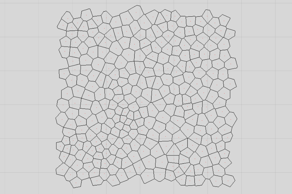
Mosaic is rendered on the texture of the library.
I make a small ScriptableObject that stores an array of calculated tiles and an editor with a large "recalculate tiles" button.
Problems with rare holes due to float in checks for a polygon hit a tile I decided to regenerate incorrect tiles. Since I make prejudices once, with my hands in the editor, I can afford it. :)
Now to display these tiles on the screen!
Todo: generate mosaic tile triangles.
 Level 5.2.2. Tile rendering.
Assume that the spot will be perfectly round and I know its coordinates and radius. You need to somehow get all the polygons that are inside this spot. In addition, the stain may appear in any coordinates, so the mosaic needs to be virtually tinted.
To test the algorithm, I created such a "mosaic", it will be easier to find problems with it: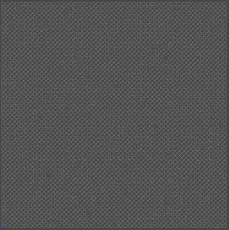
Fake mosaic
Suppose I have a mosaic generated from 512 points. So, the output will be 512 polygons and checking each one for intersection with the circle is too expensive. Therefore, I keep the mosaic in the form of small rectangular blocks:
Visualization of blocking.
Knowing the area of the mosaic and the number of polygons, you can get the optimal number of blocks at which the search speed will be maximum.
So, the search logic is as follows:
Given a circle with coordinates center and radius radius . You need to find all the polygons that fall into the circle.
- From the AABB circle, we calculate the coordinates of the first and last blocks that fall into AABB (Coordinates may be less than 0 or more rows - 1 due to tiling).
var rectSize = size / (float)rows; int minX = Mathf.FloorToInt((center.x - radius) / rectSize); int minY = Mathf.FloorToInt((center.y - radius) / rectSize); int maxX = Mathf.CeilToInt((center.x + radius) / rectSize); int maxY = Mathf.CeilToInt((center.y + radius) / rectSize); - min max;
- , ;
- :
int innerX = ((x + rows) % rows + rows) % rows; int innerY = ((y + rows) % rows + rows) % rows; - ;
- , ( ).
, , :
.
, — . :
, , . , , , {0, 0} {1, 1}, .
, :
- , ;
- ;
- .
:
:
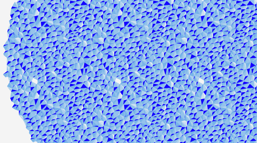
Points = 500, Relax = 5
, .
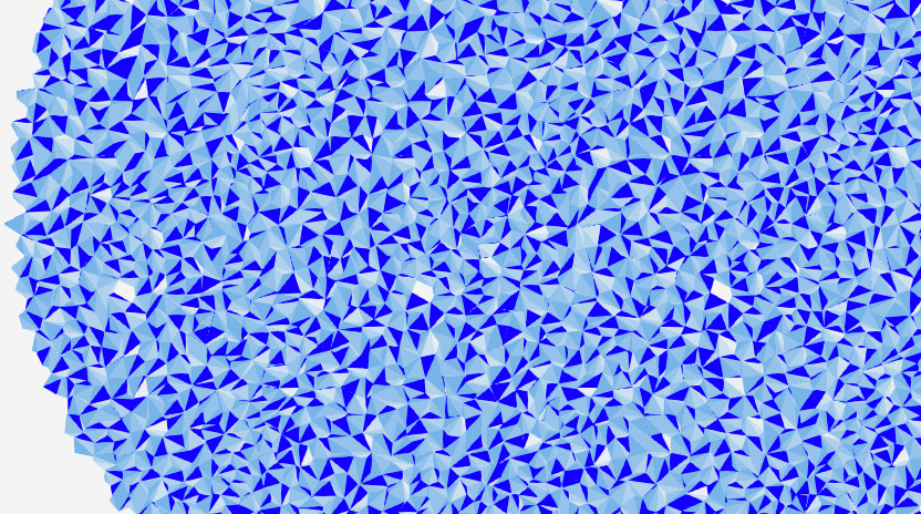
:
Points = 500, Relax = 0
: , , , :
Triangles, Points = 500, Relax = 0
. , , , : , . - "", , :
.
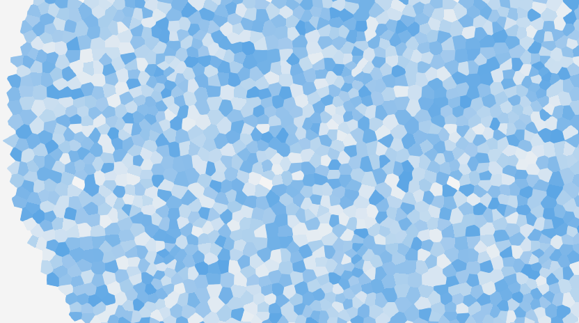
, — . , : -:
.
: , . . , "" .
Todo: .
Conclusion
, . — , . , ( ), .
, :
- . ( ) , ;
- : , , . , . :)
- Unity3D , . — frame debug, , Unity3D ( msaa).
, , .
, feedback'a!
')
Source: https://habr.com/ru/post/326840/
All Articles