Measurement of ore weight by stator current. Practice. Part 2. Software implementation at MK
The last part of the cycle "Measuring the weight of minerals . " This article will show the software implementation on the MC.
Recall the basics of this method of measuring the weight of minerals by the stator current of a mine lifting installation (silo), equipped with a high-voltage asynchronous motor with a phase-rotor.
Since the real device was not designed or manufactured, the Proteus software was used to simulate this process. This simulator supports many different MCs, and from the list of supported hardware, they chose a hardware platform for implementing the algorithm and testing the entire method.
For the convenience of testing when simulating, the original circuit in the proteus shown in the first part has undergone changes. Consider the changes.
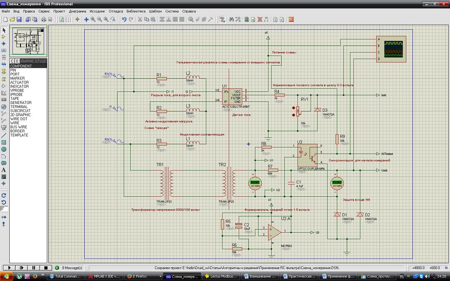
The first sheet of the scheme. The picture is clickable.
')
The changes affected the multiplication of the voltage signal, breaking the current circuit, the introduction of the inductive component into the load circuit.

The second sheet of the scheme. The picture is clickable.
The ComPim component is used to communicate with the system port. MK company Microchip. Input signals from the first sheet. Instruments (voltmeter, ammeter) for visual monitoring of voltage and current parameters. Switches are used to automatically calculate the midpoint of the current and voltage channels.
When writing a program for the PIC18F2580 MK, the free IDE MpLab X v 2.26 was used, the XC8 compiler v1.20.
During the development of the program, I had to write my own mathematical functions:
The standard functions that the compiler uses are not suitable in terms of speed, this applies to 16x16 multiplication. And there was no library function for extracting the square root from a whole 32-bit number.
The project also used custom variable types. They are introduced for ease of use.
User-defined variable types are described in the user_type.h header.
Initialization of MK is taken out in a separate module in the project. It is made according to the datasheet on the MK. Configuration bits are included in the initialization module header. For MK data, these fuses can be stitched into the firmware, in the .hex file.
Here is the leader.
We initialize the necessary periphery with our own function.
Interruptions in this MK have priority. There are only two levels: high and low. Interruption from timer 0, by which we count time intervals (samples) for measuring voltage and current signals, has a high priority, since it is time-critical, the rest is low.
According to the interruption from the detector, which is initiated by the external interrupt INT1, we start a timer with a count of 200 μs interval. By interrupting the timer, we load the preset values into it, for an accurate count, and read the ADC values from both channels and perform preliminary calculations.
In the main loop, we perform additional intermediate calculations using the Flag_izm flag.
In this implementation, communication with the "external" world is carried out using USART MK, on top of this interface the industrial protocol ModBus RTU is applied. The implementation of this protocol is quite simple and not resource intensive. Reception of messages is made in the interruption from the USART receiver
Processing of messages from the master occurs in the main loop when time-critical measurements are completed.
USART transmission is not organized in a very optimal, blocking manner.
The ModBus protocol allows the hardware developer to determine which registers in the card will be responsible for which parameter. There are no hard rules in this matter. So we will not invent something complicated and not rational.
Let's start with the first register (zero). Put in it the value of the effective voltage in the Real format, that is, the value will take up two 16-bit Modbus registers. Further, the value of current, active power, total power, cosine.
Now, when requesting the master of the values of these registers, the device will respond with quite adequate data.
To display data from the device, at this stage, we will use the OPC server. Its internal tools are enough to display data, write values to registers, etc.
For measurements, we need to calculate the average point of the sine wave voltage and current signals. In this case, we will use the algorithm described in the last article .
To automatically calculate the ADC0 channels, it is necessary to remove the useful signal from them, i.e. break the current loop into which the ACS712 current sensor is connected and connect a midpoint with an op-amp to the voltage input. Next, the algorithm will calculate the root-mean-square value of the signal, and upon a command from the master, we will add the calculated values to ADC0 for each channel and write these values to the EEPROM. After that, we connect the voltage and current signals under study.
To calculate the coefficients, we use the following procedure. After calculating the midpoint of the channels, connecting the actual signals to the analog inputs, the algorithm calculates the root-mean-square value of the voltage and current in ADC units. To convert them to physical quantities, it is necessary to measure these signals with instruments, a voltmeter and an ammeter. The values measured by the instruments are recorded in the necessary registers of Modbas, and upon a command from the master we perform the calculation of the coefficients. To reduce the length of the parcel according to Modbas, in this implementation, the value from the devices is converted to an integer value by multiplying the voltage value by 10, and the current value by 100. The obtained data is recorded in registers, and the coefficients are calculated by the wizard. The calculated coefficients are written to the EEPROM.
The weight of the ore can be calculated directly from the formula given in the first part of the story.

Where:
In this implementation, the mass measurement is not performed, since the simulation in the Proteus does not provide for such a possibility.
The simulation in the proteus makes it possible to understand the viability of the main idea: “Measuring the weight of ore during transportation in a lifting vessel using the stator current”.
The archive with the project in MpLab X and the proteus project file is here .
A video that demonstrates the processing of voltage and current signals, the calculation of active power, cosine phi, and total power is shown below.
Measuring the weight of mined minerals in industry is of great importance in technology accounting, evaluating the effectiveness of the work performed, etc.
Many different types and types of weighing devices are used to measure the mass of ore.
In this series of articles, the possibility of measuring the weight of ore was considered, according to the measurement of the developed moment of the silo drive engine during the transportation of cargo in a lifting vessel. This method is used in silos with DC motors, where the mass is calculated from the armature current with constant excitation.
PS
Since mining in the world is produced in large volumes, and there are no prerequisites for a decline, this method of measuring ore scales for technological accounting has the right to life. And maybe in the near future we will see industrial devices for measuring the mass of cargo in a lifting vessel, based on this principle.
Recall the basics of this method of measuring the weight of minerals by the stator current of a mine lifting installation (silo), equipped with a high-voltage asynchronous motor with a phase-rotor.
Instead of the preface
Since the real device was not designed or manufactured, the Proteus software was used to simulate this process. This simulator supports many different MCs, and from the list of supported hardware, they chose a hardware platform for implementing the algorithm and testing the entire method.
Foreword
For the convenience of testing when simulating, the original circuit in the proteus shown in the first part has undergone changes. Consider the changes.
The first sheet of the scheme. The picture is clickable.
')
The changes affected the multiplication of the voltage signal, breaking the current circuit, the introduction of the inductive component into the load circuit.
The second sheet of the scheme. The picture is clickable.
The ComPim component is used to communicate with the system port. MK company Microchip. Input signals from the first sheet. Instruments (voltmeter, ammeter) for visual monitoring of voltage and current parameters. Switches are used to automatically calculate the midpoint of the current and voltage channels.
Introduction
When writing a program for the PIC18F2580 MK, the free IDE MpLab X v 2.26 was used, the XC8 compiler v1.20.
During the development of the program, I had to write my own mathematical functions:
- extracting the square root of a 32-bit integer,
- taking the square root of a single-precision floating-point number,
- multiplication of unsigned integers by 16 bits,
- multiplication of integer signed numbers 16 bits.
The standard functions that the compiler uses are not suitable in terms of speed, this applies to 16x16 multiplication. And there was no library function for extracting the square root from a whole 32-bit number.
The project also used custom variable types. They are introduced for ease of use.
User-defined variable types are described in the user_type.h header.
Initialization MK
Initialization of MK is taken out in a separate module in the project. It is made according to the datasheet on the MK. Configuration bits are included in the initialization module header. For MK data, these fuses can be stitched into the firmware, in the .hex file.
Here is the leader.
#include <xc.h> /* */ #pragma config IESO = OFF #pragma config OSC = HSPLL //HS oscillator, PLL enabled (Clock Frequency = 4 x FOSC1) #pragma config MCLRE = ON //MCLR pin enabled; RE3 input pin disabled #pragma config XINST = OFF //Instruction set extension and Indexed Addressing mode disabled (Legacy mode) #pragma config PBADEN = OFF //PORTB<4:0> pins are configured as digital I/O on Reset /* */ void INT_init(void); void T0_init(void); void ADC_init(void); void USART_init(int BAUD); void T2_init(void); void PIC_init(void); We initialize the necessary periphery with our own function.
Interruptions in this MK have priority. There are only two levels: high and low. Interruption from timer 0, by which we count time intervals (samples) for measuring voltage and current signals, has a high priority, since it is time-critical, the rest is low.
Signal processing with ADC
According to the interruption from the detector, which is initiated by the external interrupt INT1, we start a timer with a count of 200 μs interval. By interrupting the timer, we load the preset values into it, for an accurate count, and read the ADC values from both channels and perform preliminary calculations.
if (Count_sample<SAMPLE){ // ADCON0bits.GO_DONE=1; // while(ADCON0bits.GO_DONE); // ADCON0bits.CHS0=0; // I_adc.byte.HB=ADRESH; I_adc.byte.LB=ADRESL; // I_int=(INT)I_adc.Val-I_0.Val; /* * * , * 88 * , * 1616=32 , * * 854 288 302 , * * , * */ I_sum+=(SLONG)mul_int(I_int,I_int); ADCON0bits.GO_DONE=1; // while(ADCON0bits.GO_DONE); // ADCON0bits.CHS0=1; // U_adc.byte.HB=ADRESH; U_adc.byte.LB=ADRESL; // U_int=(INT)U_adc.Val-U_0.Val; U_sum+=(SLONG)mul_int(U_int,U_int); P_act+=(SLONG)mul_sint(U_int,I_int); Count_sample++; } if (Count_sample>=SAMPLE){ // , Count_sample=0; Flag_izm=1; T0CONbits.TMR0ON=0; } In the main loop, we perform additional intermediate calculations using the Flag_izm flag.
if (Flag_izm){ // Flag_izm=0; if (Count_main_sample<MAIN_SAMPLE){ U_d+=(SLONG)U_sum; U_sum=0; I_d+=(SLONG)I_sum; I_sum=0; P_m+=(SLONG)P_act; P_act=0; Count_main_sample++; } } ModBus RTU protocol
In this implementation, communication with the "external" world is carried out using USART MK, on top of this interface the industrial protocol ModBus RTU is applied. The implementation of this protocol is quite simple and not resource intensive. Reception of messages is made in the interruption from the USART receiver
/* */ if (PIR1bits.RCIF){ if (RCSTAbits.FERR || RCSTAbits.OERR) { /* */ RCSTAbits.CREN=0; /* */ RCSTAbits.CREN=1; /* */ } MODBUS.rxtimer=0; /* */ if(MODBUS.rxcnt>(BUF_SZ-2)) MODBUS.rxcnt=0; MODBUS.buffer[MODBUS.rxcnt++]=RCREG1; /* ModBus*/ PIR1bits.RCIF=0; /* */ } Processing of messages from the master occurs in the main loop when time-critical measurements are completed.
if (Flag_izm){ // … if (MODBUS.rxgap){ // MODBUS_SLAVE(&MODBUS); // MODBUS.rxgap=0; } } USART transmission is not organized in a very optimal, blocking manner.
/* * */ void TX_FRAME(UART_DATA *MODBUS) { RCSTAbits.CREN=0; TXSTAbits.TXEN=1; INTCONbits.GIEH=0; /* */ INTCONbits.GIEL=0; while(MODBUS->txcnt<MODBUS->txlen){ TXREG=MODBUS->buffer[MODBUS->txcnt++]; while(!PIR1bits.TXIF) NOP(); } INTCONbits.GIEH=1; INTCONbits.GIEL=1; MODBUS->txlen=0; RCSTAbits.CREN=1; } Filling the register table ModBus
The ModBus protocol allows the hardware developer to determine which registers in the card will be responsible for which parameter. There are no hard rules in this matter. So we will not invent something complicated and not rational.
Let's start with the first register (zero). Put in it the value of the effective voltage in the Real format, that is, the value will take up two 16-bit Modbus registers. Further, the value of current, active power, total power, cosine.
res_table[0].Val=U_real.word.LW; // res_table[1].Val=U_real.word.HW; //, res_table[2].Val=I_real.word.LW; res_table[3].Val=I_real.word.HW; res_table[4].Val=P_real.word.LW; res_table[5].Val=P_real.word.HW; res_table[6].Val=P_pol.word.LW; res_table[7].Val=P_pol.word.HW; res_table[8].Val=Cos_p.word.LW; res_table[9].Val=Cos_p.word.HW; Now, when requesting the master of the values of these registers, the device will respond with quite adequate data.
To display data from the device, at this stage, we will use the OPC server. Its internal tools are enough to display data, write values to registers, etc.
Automatic determination of the midpoint of the channels and the calculation of coefficients
For measurements, we need to calculate the average point of the sine wave voltage and current signals. In this case, we will use the algorithm described in the last article .
To automatically calculate the ADC0 channels, it is necessary to remove the useful signal from them, i.e. break the current loop into which the ACS712 current sensor is connected and connect a midpoint with an op-amp to the voltage input. Next, the algorithm will calculate the root-mean-square value of the signal, and upon a command from the master, we will add the calculated values to ADC0 for each channel and write these values to the EEPROM. After that, we connect the voltage and current signals under study.
if (MODBUS.write){ if (res_table[10].Val==1){ // U_0.Val=(WORD)U_real.Val; // 0 I_0.Val=(WORD)I_real.Val; eeprom_write(0,U_0.byte.HB); // eeprom_write(1,U_0.byte.LB); //0 eeprom_write(2,I_0.byte.HB); eeprom_write(3,I_0.byte.LB); } } To calculate the coefficients, we use the following procedure. After calculating the midpoint of the channels, connecting the actual signals to the analog inputs, the algorithm calculates the root-mean-square value of the voltage and current in ADC units. To convert them to physical quantities, it is necessary to measure these signals with instruments, a voltmeter and an ammeter. The values measured by the instruments are recorded in the necessary registers of Modbas, and upon a command from the master we perform the calculation of the coefficients. To reduce the length of the parcel according to Modbas, in this implementation, the value from the devices is converted to an integer value by multiplying the voltage value by 10, and the current value by 100. The obtained data is recorded in registers, and the coefficients are calculated by the wizard. The calculated coefficients are written to the EEPROM.
if (MODBUS.write){ if (res_table[10].Val==2){ // K_u.Val=U_real.Val/res_table[11].Val; // K_u.Val*=10.0; K_i.Val=I_real.Val/res_table[12].Val; K_i.Val*=100.0; eeprom_write(4,K_u.byte.MB); // eeprom_write(5,K_u.byte.UB); eeprom_write(6,K_u.byte.HB); eeprom_write(7,K_u.byte.LB); eeprom_write(8,K_i.byte.MB); eeprom_write(9,K_i.byte.UB); eeprom_write(10,K_i.byte.HB); eeprom_write(11,K_i.byte.LB); } res_table[10].Val=0; MODBUS.write=0; } Weight calculation
The weight of the ore can be calculated directly from the formula given in the first part of the story.
Where:
- F0 - the force developed by the engine when lifting an empty vessel,
- F is the force measured when lifting a loaded vessel,
- g is the acceleration due to gravity at the weighing points.
In this implementation, the mass measurement is not performed, since the simulation in the Proteus does not provide for such a possibility.
The simulation in the proteus makes it possible to understand the viability of the main idea: “Measuring the weight of ore during transportation in a lifting vessel using the stator current”.
The archive with the project in MpLab X and the proteus project file is here .
A video that demonstrates the processing of voltage and current signals, the calculation of active power, cosine phi, and total power is shown below.
Conclusion
Measuring the weight of mined minerals in industry is of great importance in technology accounting, evaluating the effectiveness of the work performed, etc.
Many different types and types of weighing devices are used to measure the mass of ore.
In this series of articles, the possibility of measuring the weight of ore was considered, according to the measurement of the developed moment of the silo drive engine during the transportation of cargo in a lifting vessel. This method is used in silos with DC motors, where the mass is calculated from the armature current with constant excitation.
PS
Since mining in the world is produced in large volumes, and there are no prerequisites for a decline, this method of measuring ore scales for technological accounting has the right to life. And maybe in the near future we will see industrial devices for measuring the mass of cargo in a lifting vessel, based on this principle.
Source: https://habr.com/ru/post/276051/
All Articles