We are switching from STM32 to the Russian K1986BE92QI microcontroller. Practical application: Generate and reproduce sound. Part one: we generate a square and sinusoidal signal. Mastering the DAC (DAC)
Introduction
In the previous article we talked about setting the clock frequency of the microcontroller. Now I would like to consider options for working with sound: its generation and reproduction. At first I wanted to write one big article in which everything would be considered. From the generation of rectangular pulses to FLAC playback from a microSD card. But the article turned out just gigantic. So I decided to break it up into several smaller articles. In each of which I parse one peripheral module.
For those who do not like the implementation of tasks in the article.
Immediately make a reservation. I will solve the tasks set in the article only with the help of the knowledge that has already been described. I understand that using DMA, somewhere, timers, and so on will be more true. But all this will be discussed further.
Understanding the simple sound generation method.
Before writing this article, I had only a vague idea of how sound is generated, but after reading this article, everything fell into place. From the above article we can single out the most important thing - the principle.
To create a sound, we need to make the speaker membrane oscillate with a certain frequency. Each note corresponds to its own frequency, for example, a note To 1 octave, corresponds to a frequency of 261 Hz. Those. jerking the foot of the microcontroller connected to the speaker, at a speed of 261 times per second, we will hear the sound of this note. For those who are not strong in musical theory, the sound closer from 1kHz and higher will be more squeaky, below 300Hz will bass.
Our board has a Jack 3.5 connector and an amplifier for it. Consider the concept.

')
As we can see, the amplifier is connected to the controller via pin PE0. After switching the jumper “DAC_OUT_SEL” on the board, we can generate a sound that we can hear by connecting, for example, headphones to Jack.
The implementation of a simple tweeter
Armed with theory, you can try to write a program that will squeak with the frequency of the note to the first octave.
Set up our pin. Immediately agree that the code is written with the amendment to the fact that the port has nothing but our amplifier. In the future, make a universal function is not difficult.
//--------------------------------------------------------- // , . //--------------------------------------------------------- #define PER_CLOCK_PORTE (1<<25) // E. #define PORT_OE_OUT_PORTE_0 (1<<0) // PORTE_0 "". #define ANALOG_EN_DIGITAL_PORTE_0 (1<<0) // PORTE_0. #define PWR_MAX_PORTE_0 (3<<0) // PORTE_0 . #define PORT_RXTX_PORTE_0_OUT_1 (1<<0) // "1" . void Buzzer_out_init (void) { RST_CLK->PER_CLOCK |= PER_CLOCK_PORTE; // E. PORTE->OE |= PORT_OE_OUT_PORTE_0; //. PORTE->ANALOG |= ANALOG_EN_DIGITAL_PORTE_0; //. PORTE->PWR |= PWR_MAX_PORTE_0; // ( 10 ). } Now we need to decide how often we will squeak. This helped me this table of frequencies . For clarity, is presented below.
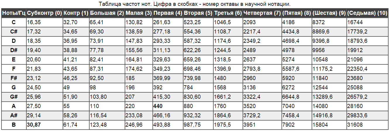
The note to (C) of the first octave has a frequency of 261.63 Hertz. This means that 261.63 periods pass in one second. In each of which we change the state of a bit 2 times. And of that, we need to change the state of the bit 523.26 times per second. Dividing 1 second to 523.26 we get 0.0019110958223445, which is approximately 191 * 10 ^ (- 5) seconds. This is a "pause" between the switchings.
Now that we know the approximate value of the delay, we can configure the SysTick timer and the delay to it. We need to configure it to interrupt once every 10 ^ (- 5) seconds. To do this, slightly change our function from this article . We get the following.
void Init_SysTick (void) // 10^(-5) . { SysTick->LOAD = (8000000/100000)-1; SysTick->CTRL |= CLKSOURCE|TCKINT|ENABLE; } volatile uint32_t Delay_dec = 0; // SysTick . void SysTick_Handler (void) { if (Delay_dec) Delay_dec--; } void Delay (uint32_t Delay_Data) // SysTick . { Delay_dec = Delay_Data; while (Delay_dec) {}; } Well, now, finally, we will use all of the above.
int main (void) { Buzzer_out_init(); // . Init_SysTick(); // 10^(-5) . while (1) // 261.63 . { PORTE->RXTX |= PORT_RXTX_PORTE_0_OUT_1; // "1" , . Delay(191); PORTE->RXTX = 0; Delay(191); } } All is good, but here the first rake. As you can see, in the main function there is not a single line of code for setting the clocking. The controller is clocked by HSI. In our example, this led to the fact that instead of a note up to the first octave, a note was played for the small octave (2 full tones lower). To correct this error, we add the function of switching the clock source from HSI to HSE (external quartz resonator).
About the clocking system was discussed in this lesson .
int main (void) { HSE_Clock_ON(); // HSE . HSE_Clock_OffPLL(); // "" HSE . Buzzer_out_init(); // . Init_SysTick(); // 10^(-5) . while (1) // 261.63 . { PORTE->RXTX |= PORT_RXTX_PORTE_0_OUT_1; // "1" , . Delay(191); PORTE->RXTX = 0; Delay(191); } } Slightly complicate the task. We write a program that will play us a range of 12 semitones (7 white keys and 5 black keys, if you look at the piano). To do this, create an array with the duration of all delays. We calculate them in the same way as the previous one: 100000 / frequency_notes / 2 = duration_delay. We divide 100,000 because we have an interruption every 0.00001 seconds (10 ^ (- 5)).
const uint32_t MES[13] = {191, 180, 170, 161, 152, 143, 135, 128, 120, 114, 107, 101, 96}; Now let's change the main function a little.
int main (void) { HSE_Clock_ON(); // HSE . HSE_Clock_OffPLL(); // "" HSE . Buzzer_out_init(); // . Init_SysTick(); // 10^(-5) . while (1) // 261.63 . { for (uint32_t Nambe = 0; Nambe<13; Nambe++) // . { for (uint32_t LoopN = 0; LoopN<MES[12-Nambe]*3; LoopN++) // . { PORTE->RXTX |= PORT_RXTX_PORTE_0_OUT_1; // "1" , . Delay(MES[Nambe]); PORTE->RXTX = 0; Delay(MES[Nambe]); } } } } A small explanation of the code. Since the length of the sound sample (one period of the sound wave) is different for each note, in order to more or less make the sound of each note the same, the waiting cycle was composed as follows. The number of the longest note (the note with the largest number of delay) sounded the “delay time” the shortest. I will explain. The note before the first octave (191) was played 96 * 3 times, and the note before the second octave (96) was played 191 times * 3. The three is the duration factor. Next will be considered a more correct way to measure the delay.
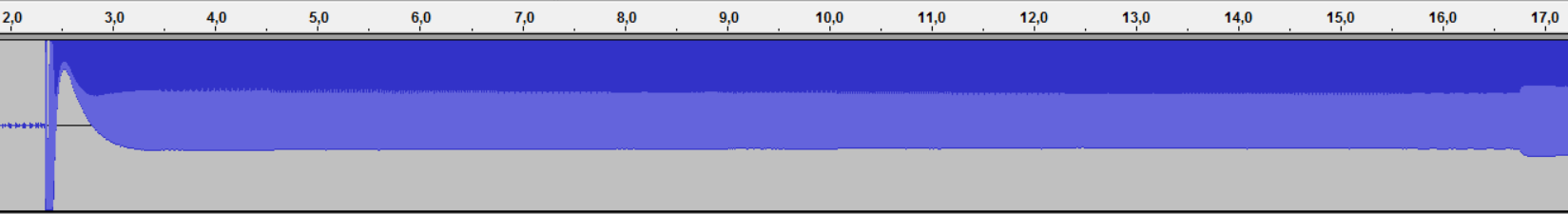
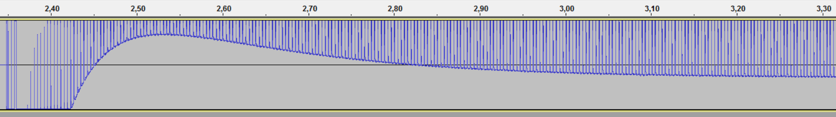
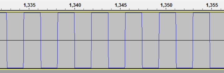
This is what our wave looks like.
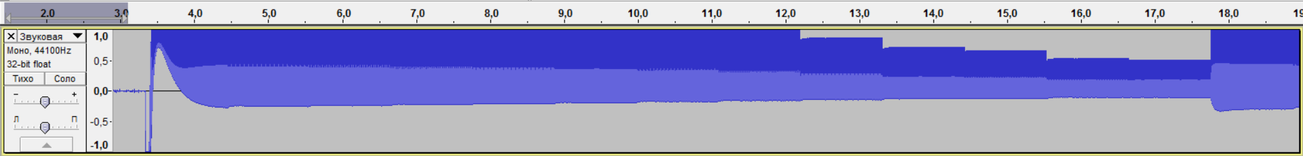
If you look closer, you can see its imperfection. It does not even closely resemble rectangular pulses.
Download the sound file here . File simple tweeters .
Mastering the DAC
Considering the pattern of our "wave" and it does not occur to the head that there is a sinusoid. Studying the issue of creating a sine wave and generally a signal of any shape on a microcontroller, I came across this article . This article came across to me for a long time. And then I read it just for fun. Now it is of practical interest. The article describes the creation and use of a simple DAC (digital-to-analog converter). A DAC is a device for converting a voltage value into, directly, the analog voltage at the output. I already wanted to collect the scheme from the article, but once again studying the documentation I saw the item.
MDR_DAC controller ................................................ .................................................. ......................... 326
It was a very pleasant surprise for me. Never before have I seen the DAC directly in the microcontroller itself. But first you need to understand whether you can connect the DAC to the amplifier. To do this, open the circuit board and see the following.
The output of our amplifier is connected directly to the PE0 to which the DAC is connected. Fine. You can start customization. But before that we will study a little DAC.
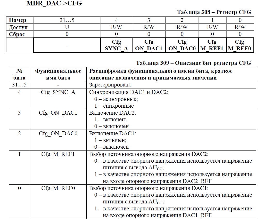
The microcontroller has two DACs. To enable the DAC, you need to set the Cfg_ON_DACx bit to 1, the used D / A port pins of the E port have been configured as analog and any internal braces have been disabled. Both DACs can work independently or jointly. When the DAC operates independently (Cfg_SYNC_A bit = 0), after writing data to the DACx_DATA data register, the voltage level corresponding to the recorded value is generated at the DACx_OUT output. During synchronous operation (Cfg_SYNC_A = 1 bit), the data of both DACs can be updated with one entry in one of the DACx_DATA registers. The DAC can operate from the internal support Cfg_M_REFx = 0, then the DAC generates an output signal in the range from 0 to the supply voltage AUCC. In the mode of operation with external support, Cfg_M_REFx = 1, the DAC generates an output voltage in the range from 0 to the value DACx_REF.
Here, we can say, described the entire setting. Take a look at the registers.
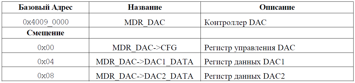
There are only three registers for two DACs here. Of these, two registers to store the value at the output of each of the DAC. Consider the register settings.
Getting Started. Just do not forget about the clocking DAC. Well, for the test, we set the maximum voltage at the output (0xFFF = 4095).
//--------------------------------------------------------- //. //--------------------------------------------------------- #define PCLK_EN_DAC (1<<18) // . #define CFG_Cfg_ON_DAC0 (1<<2) // 1. void ADC_Init (void) { RST_CLK->PER_CLOCK |= PCLK_EN_DAC; // . DAC->CFG = CFG_Cfg_ON_DAC0; // 1. . . } Next, do not forget about the exit. In the previous lesson we set it up as a digital output. Now, according to the recommendation, you need to configure as analog.
void Buzzer_out_DAC_init (void) { RST_CLK->PER_CLOCK |= PER_CLOCK_PORTE; // E. PORTE->OE |= PORT_OE_OUT_PORTE_0; //. PORTE->ANALOG = 0; //. PORTE->PWR |= PWR_MAX_PORTE_0; // ( 10 ). } Well, add all this to the main function.
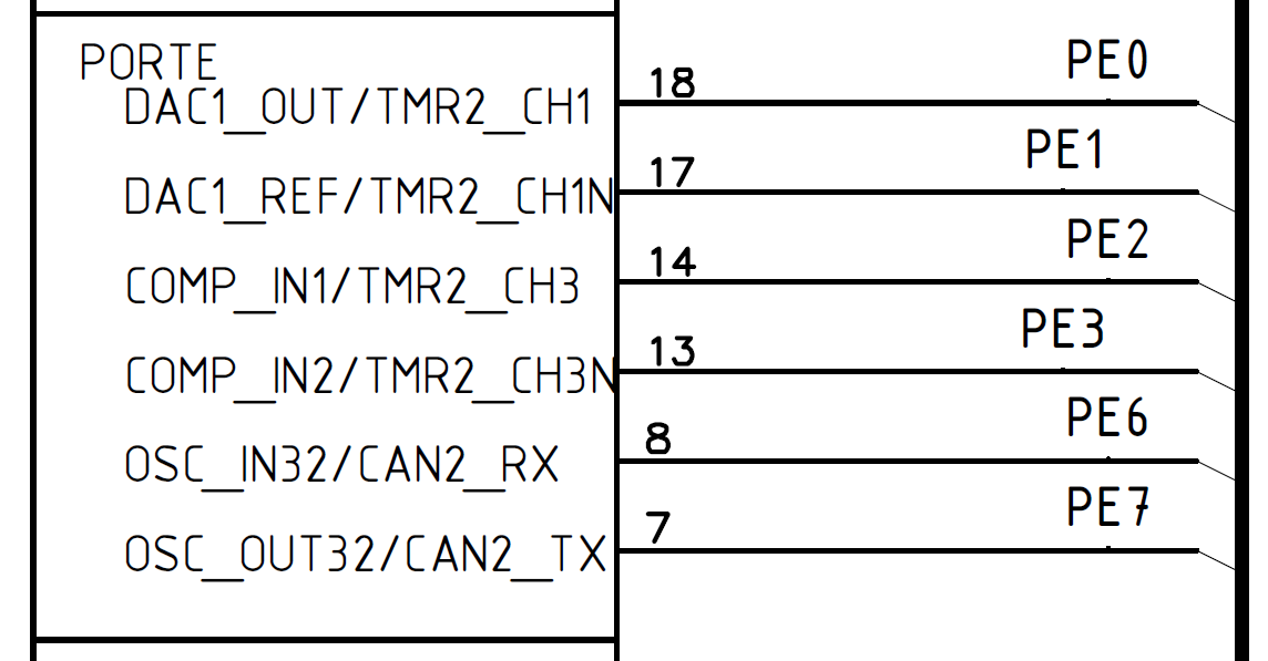
int main (void) { HSE_Clock_ON(); // HSE . HSE_Clock_OffPLL(); // "" HSE . Buzzer_out_DAC_init(); // . ADC_Init(); // . Init_SysTick(); // 10^(-5) . DAC->DAC1_DATA = 0xFFF; // (). while (1) { } } Now, if we measure the voltage on the pin, we should get about three volts. BUT. This is not happening. On the pin we have about 0.08 volts. What is not good. We go to understand. First of all, I checked if the DAC was tampered. Everything was fine. The debugger reports that all registers are filled correctly. Next, I decided to look at the pin table and found the following.
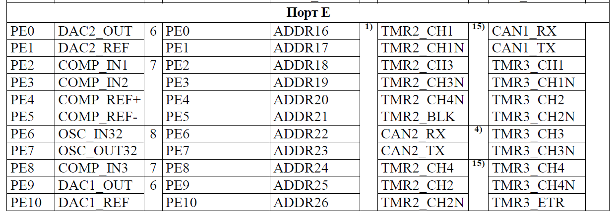
What a news. PE0 is not connected to DAC1, but to DAC2! Here is one more mistake ... We are changing the function of the DAC.
//--------------------------------------------------------- //. //--------------------------------------------------------- #define PCLK_EN(DAC) (1<<18) // . #define CFG_Cfg_ON_DAC0 (1<<2) // 1. #define CFG_Cfg_ON_DAC1 (1<<3) void ADC_Init (void) { RST_CLK->PER_CLOCK |= PCLK_EN(DAC); // . DAC->CFG = CFG_Cfg_ON_DAC1; // 2. . . } We try to run. Now everything is fine. At the output of 3.28 volts. Now, following the example of a simple tweeter, we try to generate sound with rectangular pulses. To do this, just change the code of the previous project.
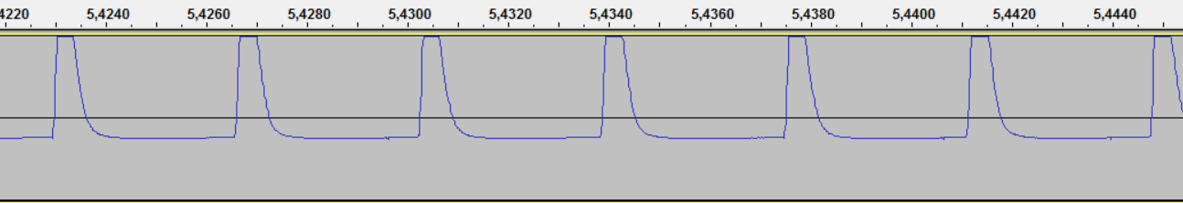
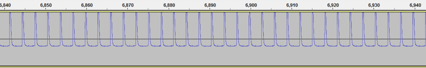
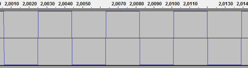
const uint32_t MES[13] = {191, 180, 170, 161, 152, 143, 135, 128, 120, 114, 107, 101, 96}; int main (void) { HSE_Clock_ON(); // HSE . HSE_Clock_OffPLL(); // "" HSE . Buzzer_out_DAC_init(); // . ADC_Init(); // . Init_SysTick(); // 10^(-5) . while (1) { for (uint32_t Nambe = 0; Nambe<13; Nambe++) // . { for (uint32_t LoopN = 0; LoopN<MES[12-Nambe]*3; LoopN++) // . { DAC->DAC2_DATA = 0xFFF; Delay(MES[Nambe]); DAC->DAC2_DATA = 0; Delay(MES[Nambe]); } } } } Purely on sensations the sound is much more pleasant than in the previous example. Yes, and it sounds much louder. Here is a sound recording . Here is the file for this project . But for comparison, our wave.
Retreat: the amplifier on the board is very hot. If you leave it in this mode for 10 minutes, it turns into a furnace ... Therefore, I turn off the jumper after listening to the sound. So it does not heat up.
Generation of a sine wave.
Having figured out how to generate a voltage at the output of a different level, I wondered where to get the values of this voltage? Literally immediately after the start of the search, I came across this article . In it, I found the most important thing. The code for obtaining the sine wave values. Slightly remaking the code, I got a program that, by querying the wavelength and sample frequency, generates an array of voltage values for our code. Here is the code on Pascal ABC (All the same, you need to prepare for the exam and sometimes write on pascal.).
Program Sin_wav; Var Real_Data, PR: double; // . samplerate: word; // . wavefrequency: double;// . Loop: word; //. Name: string; // . Begin write(' : '); readln(samplerate); // . write(' : '); readln(wavefrequency); write(' : '); readln(Name); write('const uint16_t ', Name, '[', samplerate, '] = {'); PR:=samplerate/2; // . for Loop:=0 to samplerate-1 do //-1, .. 0. Begin Real_Data := 2047*sin(Loop*pi/PR) + 2047; // sine-. //.. - 0 . // 2048-1 ( 0 4095) = 0, 2045 = -2. //2047 - . +, -. 0. write(Round(Real_Data)); if (Loop<>samplerate-1) then write(', '); End; write('};') End. I will explain a little. A sinusoid can take both positive and negative values. Our DAC can generate only positive voltage. Since the fluctuations, roughly speaking, are due to voltage changes, I decided that 0 would be at half the resolution of the DAC. In other words, 2047 = 0, 2045 = -2, 2049 = 2. The total amplitude is 4095 (If you keep score from 0). Here is an example of the execution of a code that generates a sine wave to the first octave (according to the table, the frequency of the wave is 261.63 Hertz). We will break this sinusoid into 100 plots.
Note to (C) the first octave, 100 plots.
: 100 : 261.63 : C_4 const uint16_t C_4[100] = {2047, 2176, 2304, 2431, 2556, 2680, 2801, 2919, 3033, 3144, 3250, 3352, 3448, 3539, 3624, 3703, 3775, 3841, 3899, 3950, 3994, 4030, 4058, 4078, 4090, 4094, 4090, 4078, 4058, 4030, 3994, 3950, 3899, 3841, 3775, 3703, 3624, 3539, 3448, 3352, 3250, 3144, 3033, 2919, 2801, 2680, 2556, 2431, 2304, 2176, 2047, 1918, 1790, 1663, 1538, 1414, 1293, 1175, 1061, 950, 844, 742, 646, 555, 470, 391, 319, 253, 195, 144, 100, 64, 36, 16, 4, 0, 4, 16, 36, 64, 100, 144, 195, 253, 319, 391, 470, 555, 646, 742, 844, 950, 1061, 1175, 1293, 1414, 1538, 1663, 1790, 1918}; Experiments with a sine wave.
Having received a sinusoid broken into 100 parts, we recall that this sinusoid should be played at a frequency of 261.63 hertz. Now calculate the interrupt interval. Second / (100 parts * 261, 63) = 0.00003822191 seconds. Well. I will say right away. I spent a lot of experimentation to get sound. Briefly tell about them. Since the frequency of 8 MHz was obviously not enough for such a speed, I decided to pamper myself and overclocked the chip to 80 MHz, hoping that this was enough for me. But it was not there. By setting the SysTick interrupts to 10,000,000 times per second, the controller did not even reach the cycle in which the data was output. After I decided that it would be much easier to issue data immediately in the interrupt. It turned out the following.
void Init_SysTick (void) // 10000000 . { SysTick->LOAD = (80000000/10000000)-1; SysTick->CTRL |= CLKSOURCE|TCKINT|ENABLE; } const uint16_t C_4[100] = {2047, 2176, 2304, 2431, 2556, 2680, 2801, 2919, 3033, 3144, 3250, 3352, 3448, 3539, 3624, 3703, 3775, 3841, 3899, 3950, 3994, 4030, 4058, 4078, 4090, 4094, 4090, 4078, 4058, 4030, 3994, 3950, 3899, 3841, 3775, 3703, 3624, 3539, 3448, 3352, 3250, 3144, 3033, 2919, 2801, 2680, 2556, 2431, 2304, 2176, 2047, 1918, 1790, 1663, 1538, 1414, 1293, 1175, 1061, 950, 844, 742, 646, 555, 470, 391, 319, 253, 195, 144, 100, 64, 36, 16, 4, 0, 4, 16, 36, 64, 100, 144, 195, 253, 319, 391, 470, 555, 646, 742, 844, 950, 1061, 1175, 1293, 1414, 1538, 1663, 1790, 1918}; volatile uint16_t Loop = 0; volatile uint32_t Delay_dec = 0; // SysTick . void SysTick_Handler (void) { Delay_dec++; if (Delay_dec==(382-1)) { DAC->DAC2_DATA = C_4[Loop]; if (Loop<99) Loop++; else Loop = 0; Delay_dec=0; } } The main function was:
int main (void) { HSE_Clock_ON(); // HSE . HSE_Clock_OffPLL(); // "" HSE . Buzzer_out_DAC_init(); // . ADC_Init(); // . HSE_PLL(10); //8 -> 80 . Init_SysTick(); // . while (1) { } } The sound was:

A closer look shows the following:
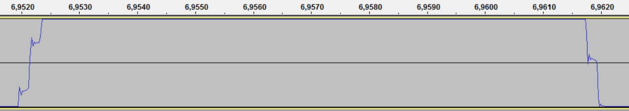
Here is an approximate increase in "sinusoid":
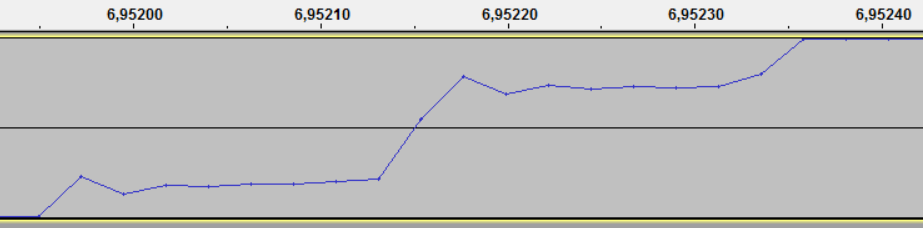
Visible huge error. And also the sound was very low. Maybe la small octave. Not higher. Which indicates that the code in the interrupt simply does not have time to run. Even with a frequency of 80 MHz. We proceed otherwise. Reduce the quality a bit. We make the interruption a little less. And round off the wait cycle in the interrupt. We get the following.
void Init_SysTick (void) // 10000000 . { SysTick->LOAD = (80000000/1000000)-1; SysTick->CTRL |= CLKSOURCE|TCKINT|ENABLE; } const uint16_t C_4[100] = {2047, 2176, 2304, 2431, 2556, 2680, 2801, 2919, 3033, 3144, 3250, 3352, 3448, 3539, 3624, 3703, 3775, 3841, 3899, 3950, 3994, 4030, 4058, 4078, 4090, 4094, 4090, 4078, 4058, 4030, 3994, 3950, 3899, 3841, 3775, 3703, 3624, 3539, 3448, 3352, 3250, 3144, 3033, 2919, 2801, 2680, 2556, 2431, 2304, 2176, 2047, 1918, 1790, 1663, 1538, 1414, 1293, 1175, 1061, 950, 844, 742, 646, 555, 470, 391, 319, 253, 195, 144, 100, 64, 36, 16, 4, 0, 4, 16, 36, 64, 100, 144, 195, 253, 319, 391, 470, 555, 646, 742, 844, 950, 1061, 1175, 1293, 1414, 1538, 1663, 1790, 1918}; volatile uint16_t Loop = 0; volatile uint32_t Delay_dec = 0; // SysTick . void SysTick_Handler (void) { Delay_dec++; if (Delay_dec==(38-1)) { DAC->DAC2_DATA = C_4[Loop]; if (Loop<99) Loop++; else Loop = 0; Delay_dec=0; } } Now the interrupt has time to handle. We get a sound almost identical to the note of Do. But still at the hearing (when compared with the piano) you can hear the inaccuracy. You can listen here . Project file here .
Our sound wave has the following form:
Raising the "sinusoid" has the following form:

As we see, there is no sense in our 100 parts. DAC just does not have time to change the voltage. (It seemed to me at the time of the study.) Let's change our project so that the sinusoid consists of 20 parts. We get the following array.
: 20 : 261.63 : C_4 const uint16_t C_4[20] = {2047, 2680, 3250, 3703, 3994, 4094, 3994, 3703, 3250, 2680, 2047, 1414, 844, 391, 100, 0, 100, 391, 844, 1414}; Calculate the interrupt frequency now. A second / (20 parts * 261.63) = 0.00019110958 seconds ~ 191 * 10 ^ (- 6). This is better than before. Configure interrupts and delay. We get the following.
void Init_SysTick (void) // 1000000 . { SysTick->LOAD = (80000000/1000000)-1; SysTick->CTRL |= CLKSOURCE|TCKINT|ENABLE; } const uint16_t C_4[20] = {2047, 2680, 3250, 3703, 3994, 4094, 3994, 3703, 3250, 2680, 2047, 1414, 844, 391, 100, 0, 100, 391, 844, 1414}; volatile uint16_t Loop = 0; volatile uint32_t Delay_dec = 0; // SysTick . void SysTick_Handler (void) { Delay_dec++; if (Delay_dec==(191-1)) { DAC->DAC2_DATA = C_4[Loop]; if (Loop<19) Loop++; else Loop = 0; Delay_dec=0; } } We got a sound even closer to the note of Do. Sound can be taken here .
Take a look at the wave:

To my surprise, practically rectangular impulses are in front of me again! Although there should have been a sinusoid. Somewhere I was wrong ... "What if I reduce the amplitude of the oscillation?" - I thought. I changed the parameter in Pascal program, which shows the “wave height” from “0” to “limit” from 2047 to 1500. But this did not lead to anything. And then I looked at the program menu in more detail and saw.

From -1 volt to 1 volt! In other words, an amplitude of 2 volts! And I had a 3 + amp! I was too lazy to look for documentation on the amplifier, therefore, by selecting I learned that the ideal amplitude is 70 * 2. Here is the code for the modified pascal program .
Program Sin_wav; Var Real_Data, PR: double; // . samplerate: word; // . wavefrequency: double;// . Loop: word; //. Name: string; // . Begin write(' : '); readln(samplerate); // . write(' : '); readln(wavefrequency); write(' : '); readln(Name); write('const uint16_t ', Name, '[', samplerate, '] = {'); PR:=samplerate/2; // . for Loop:=0 to samplerate-1 do //-1, .. 0. Begin Real_Data := 70*sin(Loop*pi/PR) + 2047; // sine-. //.. - 0 . // 2048-1 ( 0 4095) = 0, 2045 = -2. //2047 - . +, -. 0. write(Round(Real_Data)); if (Loop<>samplerate-1) then write(', '); End; write('};') End. Here is a good array:
const uint16_t C_4[20] = {2047, 2069, 2088, 2104, 2114, 2117, 2114, 2104, 2088, 2069, 2047, 2025, 2006, 1990, 1980, 1977, 1980, 1990, 2006, 2025}; Audio Recording Now take a look at our signal. Finally, something like a sine wave!

Now, when I was able to create a sinusoid of 20 parts, use the code discussed earlier, and try to make a sinusoid of 100 parts. Here is the resulting array.
: 100 : 261.63 : C_4 const uint16_t C_4[100] = {2047, 2051, 2056, 2060, 2064, 2069, 2073, 2077, 2081, 2085, 2088, 2092, 2095, 2098, 2101, 2104, 2106, 2108, 2110, 2112, 2114, 2115, 2116, 2116, 2117, 2117, 2117, 2116, 2116, 2115, 2114, 2112, 2110, 2108, 2106, 2104, 2101, 2098, 2095, 2092, 2088, 2085, 2081, 2077, 2073, 2069, 2064, 2060, 2056, 2051, 2047, 2043, 2038, 2034, 2030, 2025, 2021, 2017, 2013, 2009, 2006, 2002, 1999, 1996, 1993, 1990, 1988, 1986, 1984, 1982, 1980, 1979, 1978, 1978, 1977, 1977, 1977, 1978, 1978, 1979, 1980, 1982, 1984, 1986, 1988, 1990, 1993, 1996, 1999, 2002, 2006, 2009, 2013, 2017, 2021, 2025, 2030, 2034, 2038, 2043}; Replace the array using the old code and get this:

We got a very high quality sine wave! You can listen here . Download the project here .
Lyrical digression
While recording sound with an amplitude of> 3 Volts, speakers slightly connected to the same laptop sound card showed slightly modified sound from the device. At first, I thought it was because the background of the program was on. But as soon as it dawned on me to reduce the amplitude - I realized that it was not. Since the sound is gone. I suspect that a little bit more and I would have burned the sound card.
For recording and analyzing sound, I used the completely free Audacity program. It allows you to record sound in arbitrarily high quality without restrictions and allows you to save it in any format (including FLAC, in which I gave examples).
I also want to add that I do not have an oscilloscope. This program has replaced it for me.
Instead of a conclusion.
In the next article, the DMA module and its conjugation with the DAC will be disassembled. Files for lessons.
List of previous articles.
1. We turn from STM32F103 to K1986BE92QI. Or the first acquaintance with the Russian microcontroller.
2. We are switching from STM32 to the Russian K1986BE92QI microcontroller. Setup project in keil and flashing LED.
3. We are switching from STM32 to the Russian K1986BE92QI microcontroller. System Timer (SysTick).
4. We are switching from STM32 to the Russian K1986BE92QI microcontroller. Setting the clock frequency.
Source: https://habr.com/ru/post/255513/
All Articles