Miniature HD video translator on the virtualka: tests on 3G and 4G networks
After the first articles on the virtual network, many questions like “have you come to do such a thing that you catch on a person / bike / motorcycle / car or on an airplane / copter / boat / car and it broadcasts video to the Internet?”
Well, we decided to make such a device, especially since recently we were finally able to master the work with HD video. We also developed a simple case for the device (stl files for printing on a 3D printer are attached).
')
So in this article we will move a little away from our main doctrine, namely “remote control and video surveillance in real time”, and focus exclusively on broadcasting video to services like Ustream, YATV and others like them.
Before proceeding to the details
Permanent test HD video over WiFi (view from the window) here: www.ustream.tv/channel/virt2real-hd-test-wifi
Live tests of broadcasting via MTS and YOTA modems (view from the car) are scheduled today at around 15:00, a link to the page with all video windows : virt2real.ru/node/162
UPD> The first live tests passed today from 15:15 to 16:00
The following tests:
1. Today is March 24 from 18:30 to 19:00
2. Tomorrow, March 25, from 10:15 to 11:00.
Making a body
The task was this: to make a simple compact case for using the device in the mode "stuck in a modem, stuck in the power and the broadcast went."
No matter how bright was the imagination and ability to 3D-modeling in the head, without prototyping on something real it is impossible to take into account all the nuances of the future design. Therefore, the work began with the creation of an early prototype.
For its manufacturing, plastic corners, 3 and 5 cm wide, used by me since the time of the race on the micro-race were used. It is more convenient to use three-centimeter, since they have thinner plastic and can be cut with ordinary scissors. Of the two cut pieces, a “trough” was glued together - the bottom and long side walls. Cut the short walls separately and attached to the tape, because in the process of multiple fittings, we had to constantly remove and install them back. The thickness of the plastic turned out to be about a millimeter, and the “legs” were made of the cut squares in those places where the virtual line will be fastened with screws. Here is how the construction of the first version looked like:
After the first fitting, nuances surfaced, namely:
1. Place for camera placement
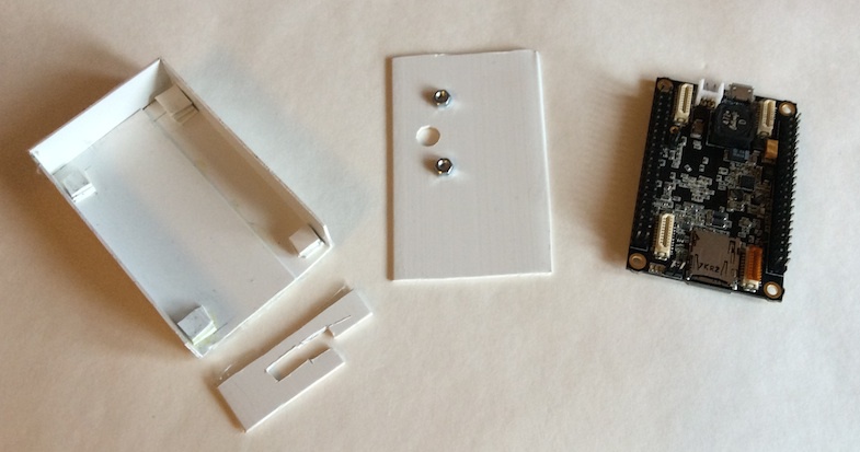
It is clear that it should be placed on the front cover. If the camera is positioned just once, bending the train, the device will have to be held vertically, which is not very convenient. Yes, and the picture will turn upside down, or the device will have to hold the wires up (power and modem). Of course, you can flip the picture programmatically, but this is an abnormal use, and this option was discarded. It was decided to do the horizontal orientation, i.e. normal position when the long side of the body is horizontal.
To check the option of attaching the camera to the lid, a hole was made and the screws on the superglue were glued.
2. Train inside the case
We have a flat train, he does not like to bend at some angles. The first thought was to make a short train (our staff - 20 cm) using a file:
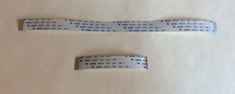
But it turned out that, firstly, a short train deprives the maneuver, and secondly, to make a qualitative shortening of the train the first time without damaging it is almost impossible. Not all owners of a virtualka have a spare train, so it was decided to leave the native length. In the case it is placed in such a way that after closing the lid does not have strong bends.
To protect against sharp bends, the usual blue electrical tape was glued along the entire cable.
3. Mounting pads
The glued legs in the places of the future location of the screws pointed to the second problem: with a large area of the legs when installing the board, some components fall on them. And when tightening the screws, you can simply “pinch” small SMD parts.
4. Nuts for fastening
Imagine, it turned out that the gadget has its thickness, and the cogs have their length! Accordingly, the screw should have a length of not less than the thickness of the virtuous plus the thickness of the nut, but not much longer so as not to crawl out from the back of the case. The trip to the hardware store enriched with triples 3, 4 and 8 mm in length (the latter for a through wi-fi rigid fixing to the board is a separate topic) and nuts for them. At the same time, a caliper was acquired, which was then repeatedly saved during design.
After all the subtleties were taken into account and the prototype case was all painted with a simple pencil, the process of creating a 3D model began.
Program

The idea was to make such a case, which anyone can print on the now fashionable and actively distributed 3D-printers. The phrase “download the case from the Internet and install your product in it” five years ago would have sounded a bit strange, but our time never ceases to amaze us.
It was decided to choose a free program with suitable functionality. I must say that I had the last experience with a 3D editor 10 years ago - it was 3DS Max, and that was only superficial. So I wanted to find a middle ground between “for dummies” and “reasonably sensible”. After downloading a few softin and playing with them, I stopped at Google SketchUp. She has a free version of SketchUp Make.
Was chosen because:
- quickly figured out, great video tutorials;
- unreal huge library of ready-made examples;
- free :)
An important point was the support for the STL format - it was him who asked me for 3D printing. In this software, you can install a plugin for exporting to STL (menu Window -> Extension Warehouse and then searching for the word STL).
There was one restriction that confused - could not draw a rectangle with rounded corners. This feature is in the pro version, and in the ordinary, you need to cut each corner separately. But after the experience with printing the model, it was thought “well and good that I did not draw rounded corners”.
The first version of the layout was with jambs - the 3D printing company said that their software swears at the lack of surfaces and does not accept the drawing of the bottom of the case. I had to thoroughly revise everything and redraw some points. The problems were in the extra planes inside the monolithic elements of the body - I found them and deleted them.
Printing on a printer.
What a geek does not like 3D printing! Last year, at a picnic in St. Petersburg, they occupied a huge area. They are now a great many, traded in many places. But there was no point in buying a printer for several cases, so a search at Yandex found several companies that could print you a sample. The choice fell on printers3d.ru for a trivial reason - they were relatively close and agreed to print quickly, rather than wait three days. The guys were responsive and adequate.
He came to visit, looked at the printers themselves and the various beautiful things that they can print.

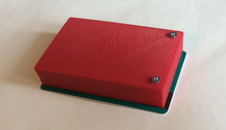
Well, then there was an immersion in the world of nuances. It was interesting to me, but how the printer prints the parts that “hang in the air”, i.e. have some space under them. It turns out that “support” is printed for them, which is deleted after printing. Or, for example, one and the same brand of plastic of different colors has slightly different properties. As a result, the black color of akilbutadiene styrene I needed at the first print gave an unfortunate result (it is in the photo on the left):

And his red brother did not suffer from such problems and everything turned out well.
The second surprise came from the desire to refine the surface of the top cover. “Acetone or solvent, better heated - and you will be happy,” say the Internet. Yeah, blessed is that who believes! If your statue is printed - yes, this is an option. And we have a cover 2 millimeters thick. Moreover, the "front" surface was on the substrate, after removing which there are deep stripes. Moreover, plastic is not monolithic: there are micro gaps between the frozen “lines” of the printer, into which the solvent is happy to be taken. The result is yes, the surface is shiny, but the lid is arched. I even thought that with proper skill you can do this in such a way.

But it helped to fix the ... boiling water. We take a metal container with a flat bottom, pour boiling water and put the lid. Tweezers pressed to the bottom - and after 10 seconds it is flat. Plastic does not become completely soft, but obedient enough to take the desired shape. The removed cover cools off in a minute and is ready for use.
And in the first version there was an inscription on the lid with convex letters, thin font - they with great difficulty are separated from the substrate on which the seal is printed.
In general, very useful bumps were stuffed. The main conclusion is that if you know the nuances, you can correctly draw a model and get a high-quality print on a 3D printer.
Stocks and tolerances
There are six places in the housing to install the nuts. The nut was carefully measured with a caliper, and the installation positions were made with a margin of about 0.1 mm on each side. Do not fit. The solution turned out to be simple - a toothpick, cotton wool, dripping solvent and a little rubbing the place to install the nut. After 30 seconds, the nut fits perfectly.
Another effect has surfaced - the dissolved plastic can play the role of glue and firmly hold the nut. But the possibility of various shrinkage and unforeseen effects kept from such a method of attachment. The installation grooves dried, nuts sat down like a glove.
I will share one more nuance on the use of superglue with gadgets. Even if the glue is taken at the tip of a toothpick and applied gently into the holes, it may be a little more than necessary there. And after installing the nut, it turns out that inside it “at the bottom” there is a certain level of glue, which clogs the thread when it dries and can shorten the natural “capacity” of the nut. Therefore, immediately after installing the nut in place, the excess glue, until they are completely liquid, it is better to remove the cotton swab or the same toothpick with cotton.
Yes, the nuts are easiest to install into the grooves not with tweezers, but by screwing them onto an 8-mm bolt.
Here you can download exactly the files that were sent to print .
Once again, we are not experts in 3D modeling, so there may be shortcomings in the design. If you want to draw an improved version - send, we will be happy!
Tuning virtual
For work, you can use the standard firmware of the HD series. A fresh version, with the settings already made of the tested modems and broadcast services, will be posted in the next few days in our topic about firmware . The key difference between this firmware and the previous one is that the camera can only work in HD 1280x720 mode. To work with lower resolutions, you need to use the previous firmware without the HD prefix.
The ideal configuration option is to work through the console and the USB-UART adapter (it is already built into our debug board for prototyping).
In short, the adjustment is done in several stages:
- We set up a virtualka on a modem - so that she recognizes him.
- For 3G modems we make from drive mode to modem mode and forcibly enable 3G mode without 2G support.
- For 3G modems, write the startup script for the pppd connection. They are different for different operators.
- The settings of the video broadcasting service to which we will broadcast are registered.
- Configuring autorun - so that after powering up, the virtual is loaded and immediately starts broadcasting.
- Those interested can upload customized firmware to NAND, then a microSD card with firmware will not be needed.
I will not describe the full process of the first trial with the settings (this applies to 3G), since they have already been made and in the firmware you only need to uncomment the lines corresponding to your modem. The firmware will be posted already this weekend - so that everyone who wants to be able to make an experiment will be able to conduct an experiment, spending quite a bit of time setting up.
Of the important points - modems love to eat. Therefore, the power supply of the virtual cell from the computer's USB port will not be enough - abundant glitches in the work are provided. So feed from an external source. I just disassembled one USB-MicroUSB cable and instead of the MicroUSB connector, I soldered the power connector of the virtual tape.
Separately, I note that 4G (the Yota modem in St. Petersburg and the Beeline modem in MSK were tested) are generally not required. Beeline modem in general Linux has on board, an interesting thing. The setup instructions look something like “Connect a modem”.
Setting up broadcast services
Pre-settings for the YATV, Ustream and YouTube services are in the corresponding scripts in the / opt / stream folder in our firmware.
You only need to add the settings of your broadcast channel. By and large, the difference is only in the last line of the script.
This is usually a translation string and a translation key. For YATV, there is still a “channel name” parameter and an app.
How to find out the video service settings for adding a virtual line to the script:
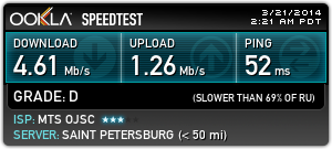
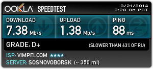
Another script parameter, targetbitrate, depends on how you intend to transfer video to the server. When compressing the stream, the virt2real board tries to “squeeze” it within the specified limits. If this is a 3G modem, then we recommend not to set the speed above 400 kbps, if the results of your speed tests do not show more.
It is better to install it according to the results of testing the speed of your modem, after conducting it in the place of the intended broadcast.
For example, here are the results of tests of modems that participate in the experiment. The tests were conditional and were conducted in St. Petersburg, the area of Komendantsky Prospect metro station, indoors (near the window):
MTS:
Beeline:
Yota:
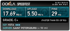
From my window one can see the tallest building on Komendantsky Avenue with a spire on the roof - therefore, the above measurements have a rather theoretical value, for presumably the antennas of the operators sit on this building. However, it should be noted that as a result of preliminary trips in some places, the 3G modem simply loses the network (it is set to forced 3G).
A few details about the video
Compression video is fraught with many nuances. The virtual player has a DSP on board, specially trained to press a video with a bunch of options - here is a description of some of the parameters available to the user in startup scripts without having to program or rebuild the kernel on the TI website .
Generally shooting scenes can be divided into two large groups. The first is “pseudo-static”, i.e. There is not a lot of movement in the frame. For example, a picture from a webcam from a high-rise window will give a pseudostatic picture. The second group is “active movement” when the image is constantly changing. For example, if you sharply jerk the camera, twist, or shoot through a side window of a fast traveling car or train, this is an active movement. It is clear that with active traffic a much wider data transmission channel is required. So, with even a very weak communication channel, the video of the pseudostatic scene can look amazing and have a high smoothness. A video with active movement even with a good channel can sometimes “lag” and twitch.
And I tell it for a reason - one of the video compression modes of our DaVinci processor is tuned to the situation when there is an active scene change in the frame, the data transfer channel is limited and we really need a high smoothness of video - i.e. good fps. This mode is enabled by setting the ratecontrol parameter to 5 (user settings) and the rcAlgo parameter to 6 (for details, see the link above). With this compression algorithm on dramatically changing scenes, the image quality will fall, but high FPS will remain. I recommend that you keep this option in mind when working with 3G modems. In general, such subtleties make sense to consider when you plan to broadcast - they can radically change the feeling of the video stream. And the DSP of our processor provides the broadest possibilities for interesting experiments.
About sound
We tested the work with the microphone and checked the video broadcast with sound. Hardware issues have been resolved (patched by a capacitor), but software issues will still require some work on our part. If there are people among habrausers who have solved problems like the one that we caught on the DM365 / 368 platform, we ask for help. Separately, the sound is transmitted without problems, separately the video - also works great, but in a combination of H.264 + AAC, stable operation has not yet been achieved.
Therefore, we conduct further combat tests in the “video only” mode.
How will live testing be conducted
Today, after three hours, we will launch live testing live. The purpose of testing is to test the reality of stable HD video broadcasting from a virtualka with the help of generally available means of cellular communication in conditions close to ordinary life. The translator will travel by car for several kilometers in order to be guaranteed to get into different conditions of receiving a cellular signal, in different light sections and with different activity scenes - from fixed to active.
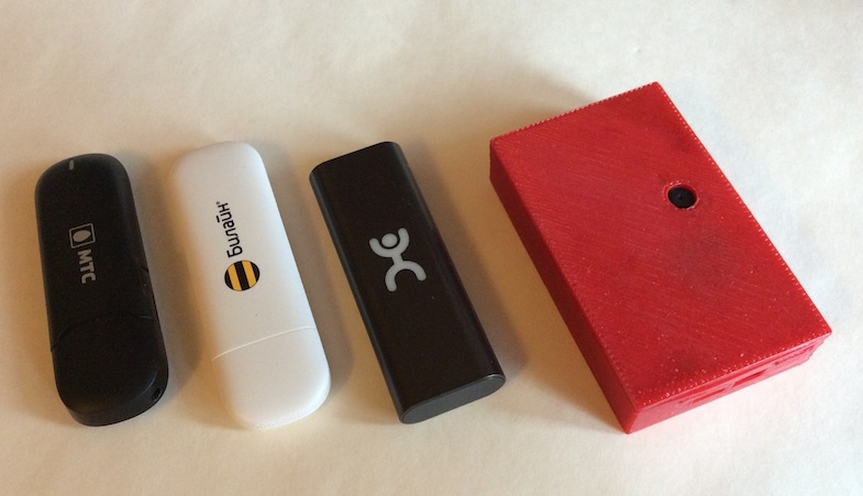
We decided not to do sequential testing of different modems, but to launch three translators simultaneously. For this, the three assembled devices were fixed in one row. Such are the three musketeers turned out:
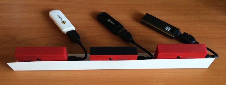
In order for the stream to be identified, each of the three Virtu- lolocs will superimpose textual information on top of the video from which provider and with which bitrate the stream is being broadcast.
Home use
As an option, it is possible to provide a hole in the case that allows the virtualka to work with the native WiFi module at home. He calmly pulls the stream into several megabits. However, at the same time, only 3 of 4 attachment points remain at the cover, so we didn’t do such a version of the case - our option is designed for active use and the cover must hold very tightly.
You can display a switch on the side panel that switches the virtual mode to the access point mode (for settings) or to the translation mode on reboot.
In general, inside we have a virtuillarika - so you can think of a sea of bells and whistles. For example, buttons for broadcasting to various services, LEDs with connection and broadcast indication, thermometer, and so on. There is someone in that much.
Link to the HD broadcast on the wifi from the window of the house is given at the very beginning of the article.
Dimensions
The description given here was made on the basis of the generic version of the virtual line without any optimizations. In this case, the body turned out to be less than a credit card in length and width:
Immediate plans
We have already drawn a diagram of the module for connecting to the virtual video of HDMI, there is a ready module for capturing analog video - but drivers have not yet been written to it. Also, an engineering sample was connected to the cooler camera ov5642, which gives a fantastically good picture. In general, the scope of work on the video part is described quite well.
For manufacturers
If you represent a company that is interested in the development or release of a finished device, similar to that described - contact us. You can vary the functionality and size of the device - for example, we can simply not install on the board side connectors and a voltage regulator, then the thickness is limited only by the height of the USB connectors and power. Write to info@virt2real.ru or in a personal on habr.
Thank you for reading!
We are also interested to hear your opinion on how much such a device will be required by you if you bring it from a prototype to a serial product. By taking part in a mini-survey, you will help us understand whether we are moving in the right direction.
Source: https://habr.com/ru/post/216583/
All Articles