How to run a program without an operating system: part 5. Accessing the BIOS from the OS
In the very first part of our series “How to run a program without an operating system”, we stopped at the fact that we loaded the kernel using GRUB and printed the classic “Hello World!” On the screen. Now we will show how you can use BIOS interrupts in the OS kernel. And for starters, let's look at what BIOS interrupts are, what they are used for, and why there are problems with calling them.
Something about interruptions
An interrupt is a signal that informs the processor of the occurrence of an event. Interrupts can be divided into 2 groups:
• external interrupts - generated by devices and other processors;
• internal interrupts — generated by the processor when any exceptional situations occur (for example, dividing by 0 or accessing invalid addresses) or by an int instruction.
In general, after an interrupt occurs, the processor must transfer control to the interrupt handler from the table pointed to by the special IDTR register. Depending on the processor's mode of operation, the table format may differ and upon a call, additional checks for the correctness of the interruption may occur.
After turning on the power, the processor starts its operation in a mode very similar to Real Mode. One of the stages of processor initialization is the transfer of control to the BIOS. The BIOS tunes some CPU registers, initializes the RAM, checks the POST devices, initializes the underlying hardware, copies the bootloader to the memory, and passes control to it. One of the BIOS steps is to set up the interrupt handler table, whose address is stored in the IDTR . This is usually 0x0 . In the real mode of the processor (Real Mode), the entry in the interrupt table consists of a pair sel: offset , which contains the address of the interrupt handler. The BIOS installs its own interrupt handlers to save the operating system from low-level hardware, which may differ from machine to machine.
')
BIOS interrupts act as an interface for working with hardware. For example, the 0x13 interrupt is used to read sectors from disks, the 0x10 interrupt is used to configure video modes. To call BIOS interrupts, a program running in Real Mode can use an int assembler instruction. For example, to read a sector from disk, you need to use the instruction int 0x13 , with parameters in general-purpose registers.
In the real mode of operation, the processor cannot access the memory above a megabyte, and it has no mechanisms for isolating running tasks (except for segmentation). Therefore, modern operating systems for the x86 platform run in other modes of operation of the processor, such as Protected Mode and Long Mode.
In Protected Mode, the interrupt table looks different. It is still indicated by the IDTR register , but the entry in this table is the Gate Descriptor of one of the 3 possible types (read clause 6.11 of the Intel manual ). The interrupt table must be configured by the operating system, not by the BIOS, therefore, in protected mode it is not possible to use BIOS interrupts. All work with devices (HDD, CD-ROM, video card ...) falls on the shoulders of the operating system, which uses for this driver. In Long Mode, the situation is exactly the same, up to the size of the Gate Descriptor.
Ways to call BIOS from protected mode
Well, what to do if the OS kernel operating in protected mode still needs to read something from the disk (for example, a hard disk driver), and the driver is not loaded yet? This can be done in two ways.
1. Configure VirtualMode86 and execute BIOS calls in Protected Mode.
2. Go to RealMode, access the BIOS, go back to Protected Mode.
Virtual Mode 86 ( VM86 ) is another processor operating mode in which segment addressing is similar to real mode, but paging the protected mode works. We will use the second method, since, using a similar technique, we can access the BIOS from 64-bit code (which is performed in LongMode, which does not support switching to VM86). Let's leave the work with the disk for later, and now we will determine the size of the RAM using the BIOS.
Strictly speaking, there is still a third way to call the BIOS from a protected 32nd mode, and that is what we used in the third part of our series for using VBE. This is the execution of a 16-bit BIOS code in a 32-bit emulator. This method is bad because it will be difficult to deliver interrupts generated by external devices to the emulator. When determining the size of RAM, external devices are not used, since the BIOS has already determined everything at the stage of its loading, and we would have approached this method to perform the task, but still use the 2nd method, since this code will still be useful to us in the subsequent articles.
Separately, it should be noted that the method chosen by us is very slow compared to the operation of the driver, as it spends a lot of time switching between CPU modes and does not use technologies such as MMIO and DMA. In addition, interrupt vectors for all devices must be configured exactly as the BIOS expects, which may not be true if drivers already work for individual devices in the system. Already running drivers, with such a transfer of control to the BIOS, will lose interrupts, which can lead to problems. All this means that you can only act in the manner described at the beginning of the OS.
We deal with the second method
So, our goal: to determine the size of the RAM by the tables e820, which we get by interrupting the BIOS int 0x15 . The e820 tables are a physical memory card that describes which physical memory ranges are available for use by the operating system. In the inaccessible regions of physical memory, the main BIOS and the video card BIOS, ACPI tables are stored, some ranges of physical memory are mapped into the memory of devices and their registers. If you start the resource monitor in Windows 7 and open the “memory” tab, the “reserved equipment” includes the amount of physical memory covered by the reserved ranges.

To get an entry from table E820, you need to write the following values to registers: 0 in EBX, 0xE820 in EAX, buffer size (at least 20 bytes) in ECX, 0x534d4150 in EDX, write to pointer to ES: DI buffer. After the int0x15 interrupt has been called, one entry from the e820 table will be written to the buffer, and the value in EBX will increase by 1. The interrupts must be repeated until the EBX is 0 again, which means the end of the table. After that, all values from the table will be in the buffer. Upon successful completion, the Carry Flag in the Eflags register will be cleared, and the value 'SMAP' will be written into EAX. A table entry has the following format:

The type is “1” if physical memory can be used by the memory manager, “2” if memory is reserved for devices or BIOS, “3” or “4” if ACPI is used. The remaining values are reserved, the ranges do not overlap. Memory card example:

Immediately make a reservation that GRUB, which we use as a bootloader, can provide a ready-made physical memory card, but the purpose of this article is to demonstrate accessing the BIOS from protected mode, and not using the capabilities of GRUB.
After starting the computer, the CPU operates in RealMode mode, in which the transfer of control to the BIOS occurs. The BIOS is free to work as it pleases, and can go into protected mode, as Coreboot does, for example. After completing its work, the BIOS loads into memory and transfers control to the first sector of the highest priority device in accordance with the boot order (at least if it is hdd or the device is emulated as hdd). The BIOS transfers control, being in RM. In our case, the load happens with the hdd and the first sector is the MBR, which transfers control to GRUB. GRUB mainly works in PM, but if necessary, it will turn to hardware (for example, read a sector from a disk) and goes to RM and uses BIOS interrupts. GRUB transfers control to our kernel in PM. The figure below shows the described sequence of CPU transitions between modes of operation during the boot process.

To continue the conversation and go directly to the code, you need to make a small theoretical indent towards the protected mode. The topic is extensive and well covered, so only what we will see in the code will be described here. The main difference between RM and PM lies in the mechanisms of segment memory addressing. What is segment memory addressing anyway? In RM, addresses with a length of 20 bits are used to access memory, but the length of the available registers is limited to 16 bits (because of this, the code is called 16-bit). Therefore, address pairs are used for addressing, one of which contains the base segment, and the second offset. The linear address is obtained by adding the offset and the base of the segment shifted to the left by 4. Segmental addressing in RM is shown in the figure below.

The offset can be stored in any general register. The base segment is stored in one of the following registers: CS, DS, SS, ES, FS, GS. These registers are called selectors . All commands have default selectors. For PUSH, POP is SS (stack segment), for JUMP, LOOP is CS (code segment), for MOV it is DS (data segment).
PM also uses segment addressing memory, but the mechanism has changed a lot. Now the selector does not store the segment base itself, but refers to a descriptor that is stored in one of the descriptor tables. The structure of the selector is shown in the figure below (and taken from Intel manuals).

• RPL (Requested Privilege Level) —used to share privilege levels in a segment protection mechanism.
• TI - indicates the type of the descriptor table in which the desired descriptor is located. 1 - LDT (Local Descriptor Table), 0 - GDT (Global Descriptor Table).
• Index - descriptor index in the descriptor table.
There are 2 types of descriptor tables - GDT and LDT. The GDT table is one for the whole system, there may be many LDT tables (for example, its own for each process). We will use GDT, since in order to use LDT, in any case, we would have to configure GDT. Descriptors can be divided into 2 groups: system and user. User descriptors are responsible for the segments. System descriptors describe processor transitions between privilege levels. In our code there will be no system descriptors, so we will not talk about them. The structure of the user descriptor, presented below (also taken from Intel manuals), suggests how long the x86 architecture appeared and how many improvements it had to endure.

A segment descriptor determines the type of segment, size, privilege level required to access it, read, write and execute permissions, and the base of the segment. Let us examine the structure of the descriptor.
• Base Address is the 32-bit address of the first byte of the segment, the field is divided into 3 parts base_0_15, base_16_23, base_24_31.
• Segment Limit - segment size in bytes, if the flag is G = 0, or in blocks of 4 Kb, if the flag is G = 1.
• G (granularity) - if the flag is set, then Segment Limit is measured in blocks of 4K, otherwise in bytes.
• S (descriptor type) - if the flag is set, then the descriptor is user, otherwise system. In our code, this flag is set for all descriptors.
• Type - the interpretation of this field depends on the flag S. For a user segment, there are 2 main options: a code segment and a data segment, this is determined by the most significant bit of the field. The table below shows all possible combinations.

The following bits are defined for the data segment: E (expansion-direction), (W) write-enable, (A) accessed. Bit (W) allows writing to a segment, (E) is used to dynamically expand a stack segment, (A) is a common bit for data and code segments, set to 1 when accessing a segment, be it read, write or execute. In the case of a code segment, the bit (E) is interpreted as ©, and (W) as ®. Bit © conforming, cancels part of the security checks when calling the code of this segment from another segment. Bit ® read enable allows reading from a code segment. Write in the code segment in protected mode is impossible.
• L (64-bit code segment) - set if the segment contains a 64-bit code. The flag can be set to 1 only for code segments.
• AVL (Available and reserved bits) - not used by the processor, the OS can be used.
• D / B (default operation size) - determines the width of custom code and data segments. 16 bits, if the flag is set to 0 and 32, if 1 (yes, yes, the 16-bit code in the protected mode also happens).
• DPL (descriptor privilege level) —determines the privilege level of the segment. It can take values from 0 to 3, where 0 is the most privileged. Used to restrict access to a segment.
Read more about the descriptor structure in the Intel System Programming Guide Part 1 , in section 3.4.5. There you can also find a description of how the division of access to segments is arranged in accordance with their level of privileges. On Habré there is a good translation on this topic.
Recall why we all started this — we need to trigger a BIOS interrupt from the C code. That is, you will need from C code to go to code in RM to ASM and then back. The C code is executed in 32-bit PM. The transition plan will look like this:

Among other things, you need to pass arguments from C code to RM code and results from RM code to C code.
! IMPORTANT! All further actions can be successfully carried out only after successful completion of all 6 steps from the first part of the article “How to run a program without an operating system”!
So, our plan:
1. Set up your own GDT table instead of the one configured by GRUB.
2. Write a wrapper to access the BIOS in C.
3. Add a few common functions.
4. Blind it all and run.
Let's get started!
Step 1. Initialize GDT
1. Add the bitvisor-1.2 \ core \ desc.h file taken from the BitVisor project to the include folder. The code can be downloaded here . The file contains the declaration of the user descriptor structure.
2. Add the file descriptor.c with the following contents:
#include "types.h" #include "desc.h" #include "string.h" static void SetSegDesc(struct segdesc *d, u32 limit, u32 base, enum segdesc_type type, enum segdesc_s s, unsigned int dpl, unsigned int p, unsigned int avl, enum segdesc_l l, enum segdesc_d_b d_b) { d->base_15_0 = base; d->base_23_16 = base >> 16; d->type = type; d->s = s; d->dpl = dpl; d->p = p; d->avl = avl; d->l = l; d->d_b = d_b; d->base_31_24 = base >> 24; if (limit <= 0xFFFFF) { d->g = 0; d->limit_15_0 = limit >> 0; d->limit_19_16 = limit >> 16; } else { d->g = 1; d->limit_15_0 = limit >> 12; d->limit_19_16 = limit >> 28; } } void SetupDescTables(struct segdesc *GDT_base) { // SEG_SEL_NULL memset(&GDT_base[0], 0, sizeof(GDT_base[0])); // . 0 // SEG_SEL_CODE32 SetSegDesc(&GDT_base[1], 0xFFFFFFFF, 0x00000000, // 32 SEGDESC_TYPE_EXECREAD_CODE, // 0 SEGDESC_S_CODE_OR_DATA_SEGMENT, 0, 1, // 0 4G 0, SEGDESC_L_16_OR_32, SEGDESC_D_B_32); // SEG_SEL_DATA32 SetSegDesc(&GDT_base[2], 0xFFFFFFFF, 0x00000000, // 32 SEGDESC_TYPE_RDWR_DATA, // 0 SEGDESC_S_CODE_OR_DATA_SEGMENT, 0, 1, // 0 4G 0, SEGDESC_L_16_OR_32, SEGDESC_D_B_32); // SEG_SEL_CODE16 SetSegDesc(&GDT_base[3], 0x0000FFFF, 0x00000000, // 16 SEGDESC_TYPE_EXECREAD_CODE, // 0 SEGDESC_S_CODE_OR_DATA_SEGMENT, 0, 1, // 0 4G 0, SEGDESC_L_16_OR_32, SEGDESC_D_B_16); // SEG_SEL_DATA16 SetSegDesc(&GDT_base[4], 0x0000FFFF, 0x00000000, // 16 SEGDESC_TYPE_RDWR_DATA, // 0 SEGDESC_S_CODE_OR_DATA_SEGMENT, 0, 1, // 0 4G 0, SEGDESC_L_16_OR_32, SEGDESC_D_B_16); struct descreg gdtr; gdtr.base = (ulong)GDT_base; // gdtr.limit = 5 * sizeof(*GDT_base) - 1; // - 1 __asm__ volatile ("lgdt %0" // GCC-Inline-Assembly : : "m" (gdtr)); } For the operation of the C code, 2 user segments are enough: a 32 bit code segment and a 32 bit data segment. To go to the 16-bit code, we need two additional segments: 16-bit code and data segments. The SetupDescTables function generates a GDT table with five descriptors at the * GDT_base address, the first of which is zero, and the remaining 4 correspond to the segments described above. All segments have a base of 0 and 4G limit. The first descriptor in GDT should always be zero. The GDTR register, which points to GDT, is initialized with the lgdt instruction. To invoke the instruction, an assembler insert with a specific GCC syntax is used. Assembler inserts have the following structure:
asm ( assembler template : output operands /* optional */ : input operands /* optional */ : list of clobbered registers /* optional */ ); The used asm insert is converted to the following code:

Strictly speaking, in order for the GDT table to be used, the values of the corresponding selectors must be loaded into the CS, SS, DS registers. But at this stage it is not so critical.
3. Add a call to SetupDescTables and several declarations in kernel.c . The result is the following:
#include "printf.h" #include "screen.h" #include "types.h" #include "desc.h" #include "callrealmode.h" struct segdesc g_GDT[5]; void SetupDescTables(struct segdesc *GDT_base); void kmain(void) { clear_screen(); printf(" -- Kernel started! -- \n"); SetupDescTables(g_GDT); u64 ram_size = GetAvalibleRAMSize (); printf("ram_size = %llu(%lluMb)\n", ram_size, ram_size / 0x100000); } The call to GetAvalibleRAMSize () returns the size of the RAM in bytes.
Step 2. Add some common functions.
1. Add the bitvisor-1.2 \ core \ string.s file to the common folder, the bitvisor-1.2 \ core \ longmode.h and bitvisor-1.2 \ include \ core \ string.h files from the BitVisor project to the include folder . These files contain the implementation of several general purpose functions, such as memcpy and memset. Content include \ types.h replace with the following:
#ifndef _TYPES_H #define _TYPES_H #define NULL 0 typedef unsigned long size_t; typedef unsigned long ulong; typedef unsigned char u8; typedef unsigned short u16; typedef unsigned int u32; typedef unsigned long long u64; #endif Step 3. Appeal to BIOS
1. Add a segment.h file to include , containing selector values for the descriptors defined in the SetupDescTables function.
#ifndef _SEGMENT_H #define _SEGMENT_H #define SEG_SEL_NULL 0 #define SEG_SEL_CODE32 (1 * 8) // Index = 1, TI = 0, RPL = 0 #define SEG_SEL_DATA32 (2 * 8) // Index = 2, TI = 0, RPL = 0 #define SEG_SEL_CODE16 (3 * 8) // Index = 3, TI = 0, RPL = 0 #define SEG_SEL_DATA16 (4 * 8) // Index = 4, TI = 0, RPL = 0 #endif and the callrealmode.h file, with the GetRamsize function prototype .
#ifndef _CALLREALMODE_H #define _CALLREALMODE_H #include "types.h" u64 GetAvalibleRAMSize(); #endif 2. Add the callrealmode.c file to the root of our project with the following contents:
#include "printf.h" #include "types.h" #include "string.h" #include "segment.h" #include "callrealmode_asm.h" // interrupts and paging must be disabled static void callrealmode_Call(struct callrealmode_Data *p_param) { u16 sp16; u32 sp32; // copy 16 bit code and stack // memcpy 16 // callrealmode_start callrealmode_end // CALLREALMODE_OFFSET < 1Mb. // , RM // 1Mb. memcpy ((u8*)CALLREALMODE_OFFSET, &callrealmode_start, &callrealmode_end - &callrealmode_start); // , , . // RM , SP // sp16 = CALLREALMODE_OFFSET - sizeof(*p_param); // memcpy memcpy ((void*)(u32)sp16, p_param, sizeof(*p_param)); __asm__ volatile ( "mov %%esp,%0\n" // ESP sp32 "mov %1,%%ds \n" // 16 "mov %1,%%es \n" // DS, ES, FS, GS, SS "mov %1,%%fs \n" // "mov %1,%%gs \n" // "mov %1,%%ss \n" // "mov %2,%%esp\n" // 16 sp16 "pusha \n" // "lcall %3,%4 \n" // 16 CS // CALLREALMODE_OFFSET. // CS EIP, // // lretl 32 "popa \n" // "mov %5,%%ds \n" // 32 "mov %5,%%es \n" // DS, ES, FS, GS, SS "mov %5,%%fs \n" // "mov %5,%%gs \n" // "mov %5,%%ss \n" // "mov %0,%%esp\n" // 32 , // sp32 : "=&a" (sp32) // %0 – Input : "b" ((u32)SEG_SEL_DATA16) // %1 - Output , "c" ((u32)sp16) // %2 - Output , "i" ((u32)SEG_SEL_CODE16) // %3 - Output , "i" (CALLREALMODE_OFFSET) // %4 - Output , "d" ((u32)SEG_SEL_DATA32) // %5 - Output ); // 16 p_param memcpy (p_param, (void*)(u32)sp16, sizeof(*p_param)); } u64 GetAvalibleRAMSize() { struct callrealmode_Data param; // , // RM, u64 avalible_ram_sz = 0; param.func = CALLREALMODE_FUNC_GETSYSMEMMAP; param.getsysmemmap.next_num = 0; do { param.getsysmemmap.num = param.getsysmemmap.next_num; callrealmode_Call(¶m); // int 0x15, EBX = param.getsysmemmap.num // EAX = 0xE820, EDX = 0x534d4150, ECX = 20 // ES:DI = ¶m.getsysmemmap.base // EBX // param.getsysmemmap.next_num = EBX // SYSMEMMAP_TYPE_AVAILABLE if (SYSMEMMAP_TYPE_AVAILABLE == param.getsysmemmap.type) { avalible_ram_sz += param.getsysmemmap.len; } printf("n 0x%08X nn 0x%08X b 0x%08llX l 0x%08llX(%lldMb) t 0x%08X\n", param.getsysmemmap.num, param.getsysmemmap.next_num, param.getsysmemmap.base, param.getsysmemmap.len, param.getsysmemmap.len / 0x100000, param.getsysmemmap.type); } while (param.getsysmemmap.next_num); return avalible_ram_sz; } We have reached the most interesting! There are 2 functions in this code: GetRamsize and callrealmode_Call . The GetRamsize function forms the param callrealmode_Data structure to call the callrealmode_Call . The callrealmode_Call function directly goes to the 16-bit code on the assembler. On its basis, you can write other functions that access the BIOS, for example, the sector read from disk function. The only condition is to use the callrealmode_Data structure.
The GetRamsize function implements in its logic a mechanism for obtaining a physical memory card through an int0x15 interrupt, repeatedly calling the callrealmode_Call function (analogous to int0x15) until param.getsysmemap.next_num (also EBX) becomes zero. The callrealmode_Call function uses two assembler tags on the assembler tags callrealmode_start and callrealmode_end to copy the entire 16-bit code to the lower megabyte at CALLREALMODE_OFFSET = 0x5000 . The address is selected so that when copying, do not rub the BIOS structures. Assembler insertion is of the greatest interest in the function, it is well commented, so we will just show what it has become in the compiled form:

3. Add the callrealmode_asm.h file to the include folder, the file can be taken here , and the callrealmode_asm.s file to the source root, which can be taken here . The first file contains the definitions of structures used in callrealmode.c . The second file contains a 16-bit code for the assembler, in which you go to RM, call BIOS, return to PM and then to code C. The code is commented in detail and can be dealt with. It should be noted that the protection_off and protection_on procedures used to transition between PM and RM are greatly simplified. They forget about the part of the registers, such as CR3, some MSR, the values of which need to be saved and restored, as it happens with GDTR and IDTR. A more complete implementation of these functions can be found in the BitVisor project, namely, in bitvisor-1.2 \ core \ callrealmode_asm.s .
Step 4. Last improvements and launch
1. Make changes to the makefile. Replace
OBJFILES = \ loader.o \ common/printf.o \ common/screen.o \ kernel.o on
OBJFILES = \ loader.o \ common/printf.o \ common/screen.o \ common/string.o \ kernel.o \ callrealmode.o \ callrealmode_asm.o \ descriptor.o And the line
as -o $@ $< on
as -I include -o $@ $< 2. Reconstruct the project:
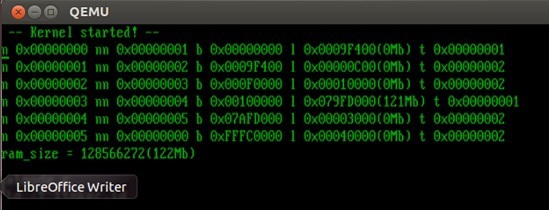
make rebuild sudo make image 3. Run with the option “–m”, which allows you to explicitly specify the size of RAM. You should have something like the following:
sudo qemu-system-i386 -hda hdd.img –m 123 
The program prints all available memory ranges. As in the previous parts, you can make the dd image of hdd.img on a flash drive and check the code on a real hardware by booting from it.
Future plans
As a result, we received a mechanism that allows accessing the BIOS from the code on C. In addition, the theoretical part concerning the operation of the protected mode was affected. In the future, this article can be used as a starting point to demonstrate how to work with the FAT32 file system, but more on that next time!
Link to the following cycle article:
" How to run a program without an operating system: part 6. Support for working with disks with the FAT file system "
Source: https://habr.com/ru/post/211470/
All Articles