Weather Station on Arduino from A to Z. Part 4
Continued. The previous part .
Table of contents:
- Part 1. Requirements. The choice of iron. General scheme
- Part 2. Software. Central unit, iron
- Part 3. Central unit, software
- Part 4. Transom Sensor
- Part 5. MySQL, PHP, WWW, Android
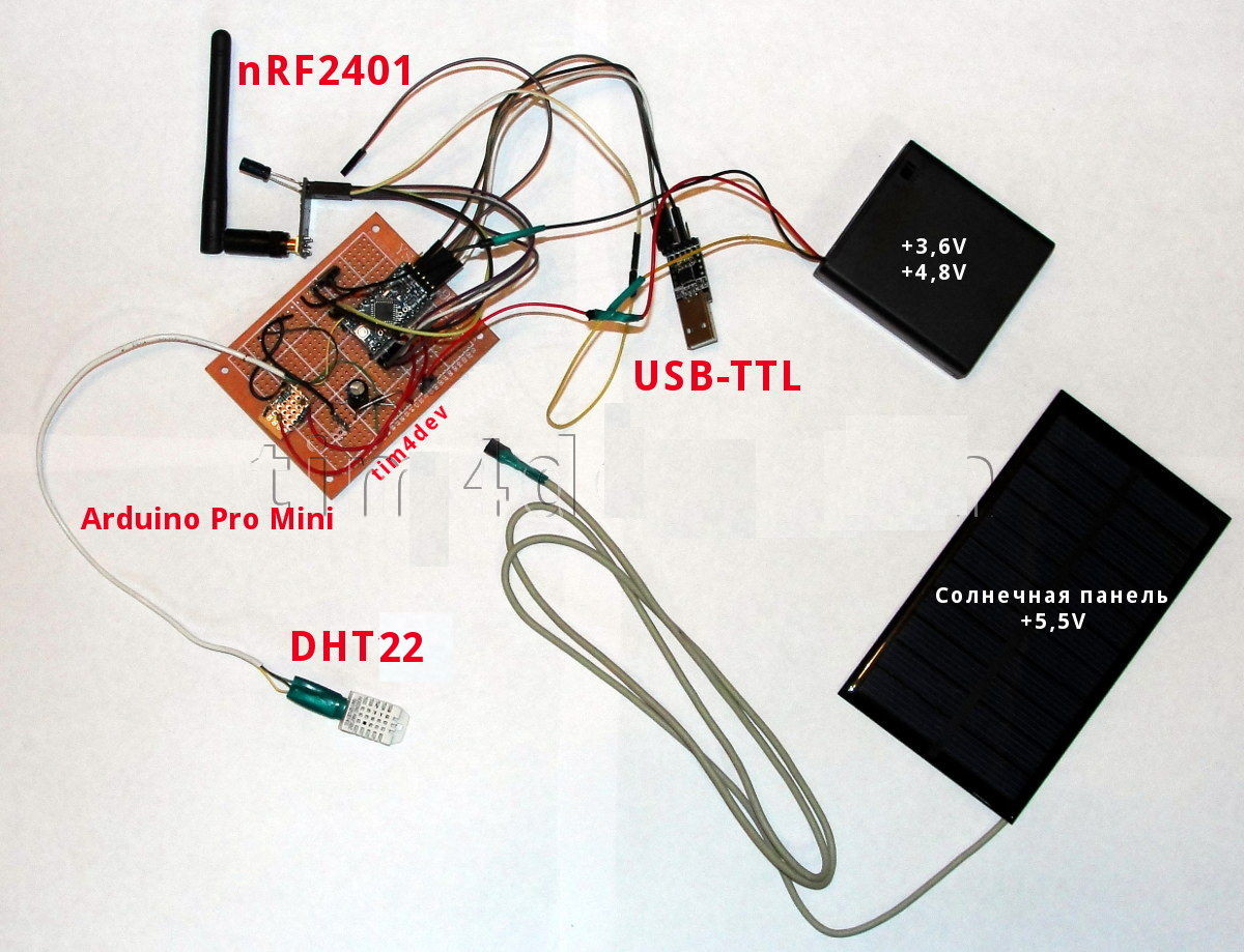
Window sensor. Iron
We must immediately recognize that the first version of the remote (remote) sensor turned out to be not entirely successful in terms of power supply and power consumption. As I already wrote, I only had the Arduino Pro Mini 5V module on hand. And I used Ni-MH batteries.
Given that I also connected the solar battery, the whole design worked autonomously for about 25 days. The battery capacity was very negatively influenced by low, often negative temperatures on the street at the end of winter.
To make everything work for you much longer, make the following replacements:
- Buy a 3.3V Arduino Pro Mini
- Use a Li-ion battery type Panasonic NCR18650A 3.7 V, 2 pcs. for about $ 14 at 3100mAh. You can try CR123, CR123A batteries. And remember that a 9V battery (such as "Kron") is a bad power source.
The main thing to remember is that your batteries will work on the street, i.e. at negative temperatures, which slow down the chemical processes occurring inside them and, thereby, greatly reduce their capacity.
The DHT22 sensor can work from 3.3 V, so it's all the way through.
The above permutations will not entail rework or replacement of other components.
Nutrition
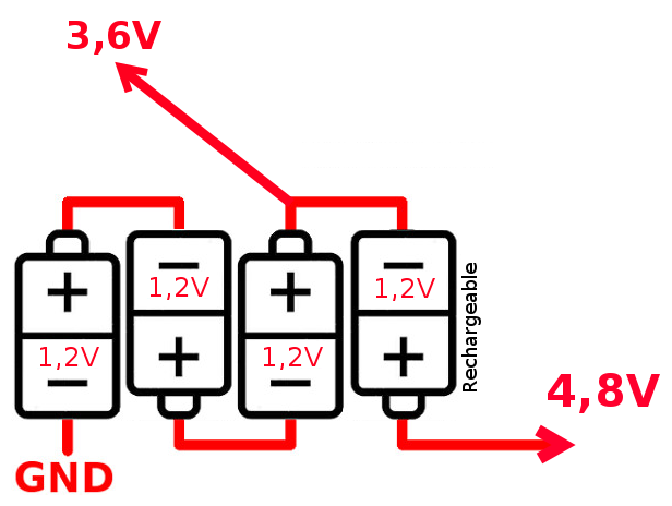
I initially used 4 pcs. Ni-MH battery connected in series with the removal of the third, so it turned out two supply voltage: 4.8 V for the DHT22 sensor and 3.6 V for everything else. I did not use lowering (or more precisely energy-destroying) or step-up electronic circuits, only environmentally friendly voltage and current.
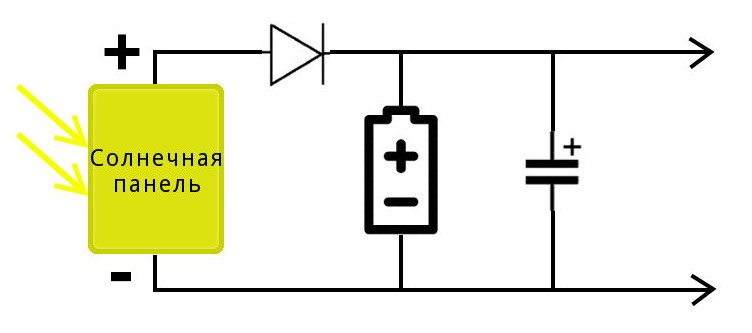
The solar panel is connected as shown. Solar panel 1.6W 5.5V 266mA was bought for $ 6.64.
The circuit uses a Schottky diode of type 1N914 and an electrolytic capacitor of 50-100 μF.
Pinout and connection
We proceed to the assembly.
Temperature and humidity sensor DHT22
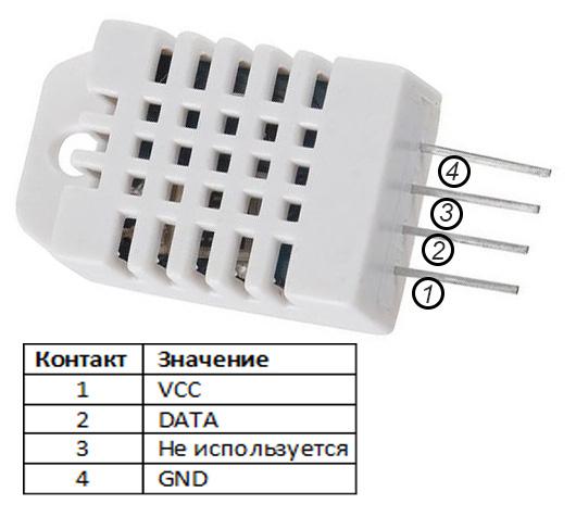
Pinout for connecting temperature and humidity sensor DHT22:
| DHT22 front side from left to right | Arduino Pro Mini | Note |
|---|---|---|
| VCC | 3.3 - 5V | 5V recommended, better external power |
| SDA | D2 | In the sketch it is DHTPIN |
| NC | Not connected | |
| GND | GND |
Optionally, you can connect (pull) SDA through a 10K resistor to VCC.
Initialization:
#define DHTPIN 2 // D2 DHT dht(DHTPIN, DHTTYPE); To protect the sensor from direct sunlight, I made a casing for it from a tin can, pasted on top with reflective metallic tape.
nRF24L01 +
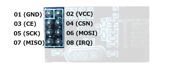
Pinout of the nRF24L01 + radio module (look at the top of the board where the chip is, with the pin pins at the bottom):
| (2) 3.3V | (4) CSN | (6) MOSI | (8) IRQ |
| (1) GND | (3) CE | (5) SCK | (7) MISO |
Connection nRF24L01 +
| Arduino Pro Mini | nRF24L01 + | Note |
|---|---|---|
| 3.3V | VCC (2) | Better external power |
| pin D8 | CE (3) | chip enable in |
| SS pin D10 | CSN (4) | chip select in |
| SCK pin D13 | SCK (5) | SPI clock in |
| MOSI pin D11 | SDI (6) | SPI Data in |
| MISO pin D12 | SDO (7) | SPI data out |
| IRQ 8 | Interrupt output, not connected | |
| GND | GND (1) |
Initialization:
NRF24 nrf24(8, 10); As advised on the forums, the nRF24L01 + power supply terminals immediately soldered a small capacitance electrolytic capacitor (10µF).
I have a radio module with an external additional antenna; it “breaks through” two walls reliably.
Voltmeter
The window sensor has a voltmeter to measure the battery supply voltage. The measurement technology is described by Scott Daniels "Secret Arduino Voltmeter - Measure Battery Voltage", 2012.
Data is read from analog pin A1.
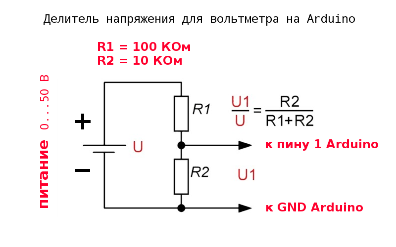
I have voltage divider resistors for 100 KΩ and 10 KΩ (you may have slightly different ratings, you must accurately measure them with an ohm meter).
const float r1 = 100400; // 100KOm const float r2 = 9960; // 10KOm The following constant must be calibrated individually as described by Scott Daniels. Using a separate scheme and sketch .
We measure two Vcc values: real Vcc with a voltmeter (on an AREF pin or 5V) and Vcc with our function. Then replace the constant ( 1.1 * 1023.0 * 1000 ) with a new one:
scale_constant = internal1.1Ref * 1023 * 1000 where internal1.1Ref = 1.1 * Vcc1 ( ) / Vcc2 ( )
Where
- Vcc1 - Vcc value measured manually with a voltmeter
- Vcc2 - Vcc value defined by our function
This reference value will be individual for a particular AVR chip and will depend on temperature fluctuations.
As a result, I got the following value:
const float typVbg = 1.082; // 1.0 — 1.2 As our rechargeable battery discharges in the dark and recharges from a solar battery, the voltage chart will look like a sawtooth, “sagging” on cloudy days:
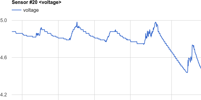
The graph is real, taken from the web of the project.
Assembly
To assemble the unit as a whole, I again used a prototype soldering board.
Payal, connected on a whim, without prior wiring, so I have no scheme.
That's what happened.
')
Source: https://habr.com/ru/post/425963/
All Articles