AVR Audio Player

During the next revision of electronic junk and shoving in boxes, I came across an AVR atxmega256a3u controller. In order to allay the boredom, it was decided to make some kind of sound card, or rather DAC, connected to a computer. What came out of this look under the cut.
The XMEGA microcontroller line is a development of MEGA controllers familiar to most electronics lovers, many interesting buns have been added, but everything described below can be implemented on a traditional series. I recommend only to use those controllers, where more RAM.
From words to design, after reflection, I came to this structure of the device:
')

I will play music from wav files, mono, 8 bits with a sampling frequency of 44.1 kHz. Sending a serial port consists of 10 baud (start and stop bits, 8 data bits), which means that a speed of at least 441 kBaud / s is required. The equipment allows you to work faster, I take 2000 kB / s data transfer rate with reserve.
Inside the controller is a FIFO buffer, it’s also the first-come-first-out queue. On a timer with a frequency of 44.1 kHz, an interrupt is started which extracts the next sample from the buffer and transmits it to the D / A converter, and also requests the next data packet from the computer, if necessary. Thinking about all this, I trace and harass the "debug" board for the microcontroller:
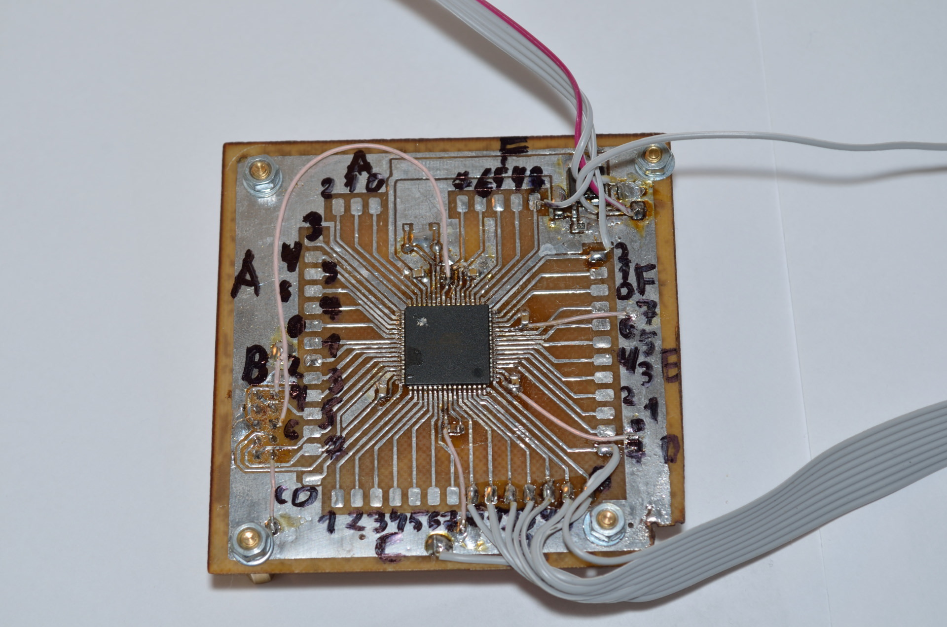
Perhaps the most interesting in this development is the DAC. There is a built-in DAC in my microcontroller, but it is not sporty to use it, besides, most microcontrollers do not have this luxury. Do not worry, you can make a DAC yourself from a handful of resistors according to the R-2R scheme:
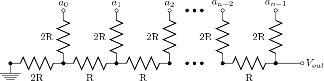
This scheme allows you to get the output voltage in the range from 0 V to the level of the logical unit, in my case it is 3.3 V. I will do an eight-bit DAC, I have only resistors with a tolerance of 5%, which means accuracy will be lost from the fifth digit because (1 /2^5)<0.05. Nevertheless, I hope that the lower digits will allow to voice the weak spectral components of the signal. I collect from resistors with a nominal value of 5.1 kOhm such a monster:
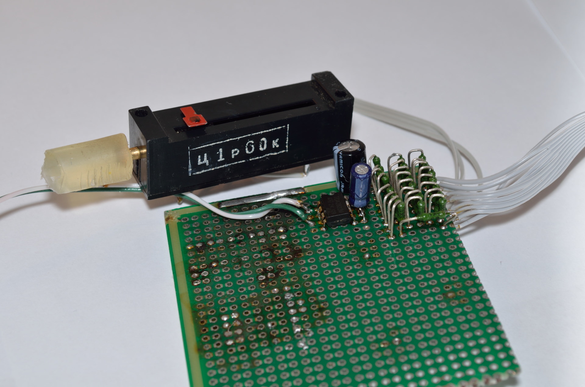
Immediately I put the amplifier TDA2822M, I connect on a bridge circuit from the datasheet:

And doing a column with a phase inverter:
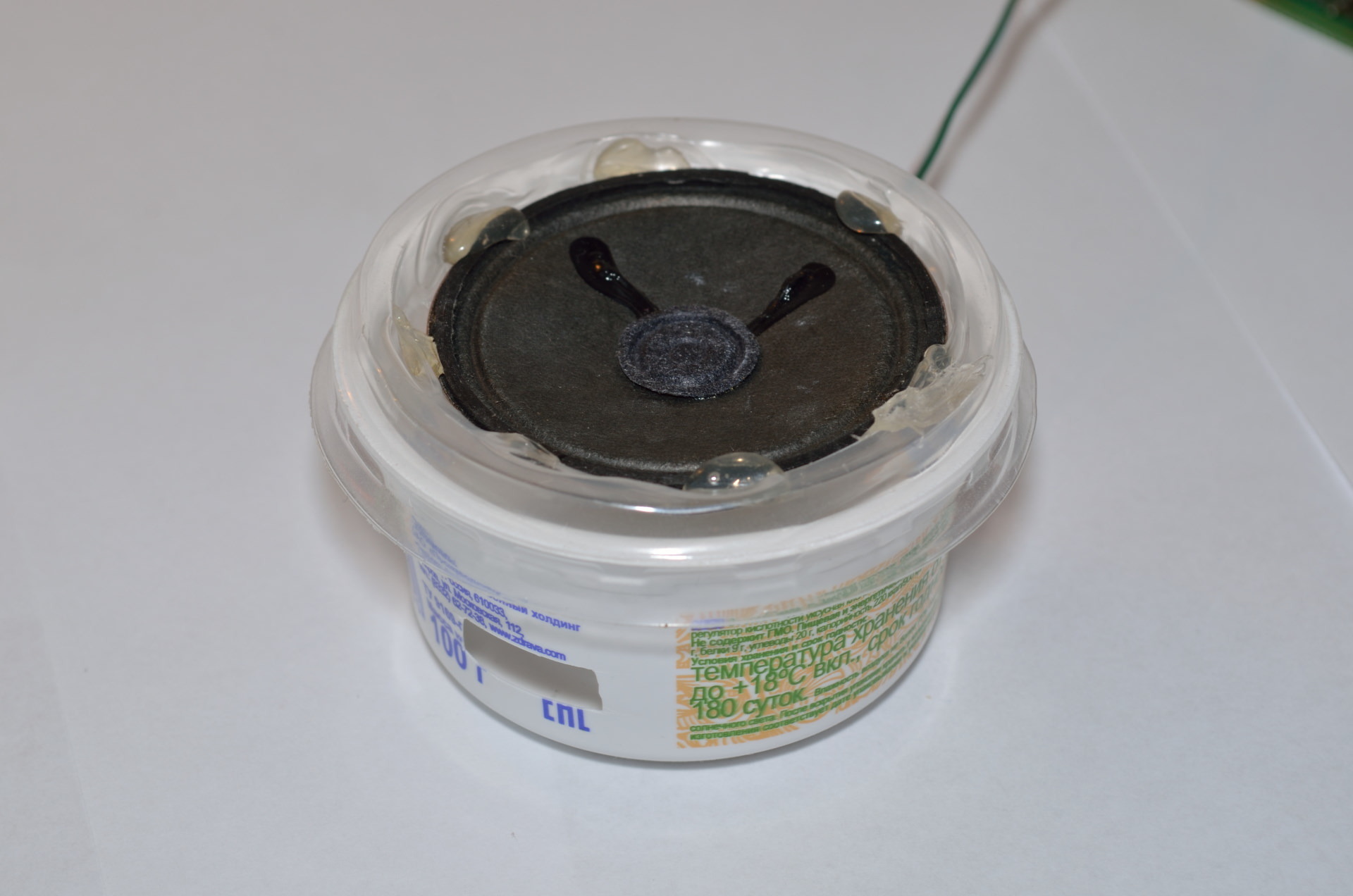
It's time to listen:
It sounds more or less tolerable, if you connect a bigger speaker, it gets better.
Code for MK
Carefully, a code generator is used for initialization. There is the possibility of using the internal DAC.
// I/O Registers definitions #include <io.h> // Declare your global variables here #define fSIZE 12000 int rAdr,wAdr,dn; char needdata; char fifo[fSIZE]; // System Clocks initialization void system_clocks_init(void) { unsigned char n,s; // Optimize for speed #pragma optsize- // Save interrupts enabled/disabled state s=SREG; // Disable interrupts #asm("cli") // External 16000,000 kHz oscillator initialization // External Clock Source - Startup Time: 0.4-16 MHz Quartz Crystal - 16k CLK OSC.XOSCCTRL=OSC_FRQRANGE_12TO16_gc | OSC_XOSCSEL_XTAL_16KCLK_gc; // Enable the external oscillator/clock source OSC.CTRL|=OSC_XOSCEN_bm; // System Clock prescaler A division factor: 1 // System Clock prescalers B & C division factors: B:1, C:1 // ClkPer4: 16000,000 kHz // ClkPer2: 16000,000 kHz // ClkPer: 16000,000 kHz // ClkCPU: 16000,000 kHz n=(CLK.PSCTRL & (~(CLK_PSADIV_gm | CLK_PSBCDIV1_bm | CLK_PSBCDIV0_bm))) | CLK_PSADIV_1_gc | CLK_PSBCDIV_1_1_gc; CCP=CCP_IOREG_gc; CLK.PSCTRL=n; // Wait for the external oscillator to stabilize while ((OSC.STATUS & OSC_XOSCRDY_bm)==0); // Select the system clock source: External Oscillator or Clock n=(CLK.CTRL & (~CLK_SCLKSEL_gm)) | CLK_SCLKSEL_XOSC_gc; CCP=CCP_IOREG_gc; CLK.CTRL=n; // Disable the unused oscillators: 2 MHz, 32 MHz, internal 32 kHz, PLL OSC.CTRL&= ~(OSC_RC2MEN_bm | OSC_RC32MEN_bm | OSC_RC32KEN_bm | OSC_PLLEN_bm); // ClkPer output disabled PORTCFG.CLKEVOUT&= ~(PORTCFG_CLKOUTSEL_gm | PORTCFG_CLKOUT_gm); // Restore interrupts enabled/disabled state SREG=s; // Restore optimization for size if needed #pragma optsize_default } // Ports initialization void ports_init(void) { // PORTA initialization // OUT register PORTA.OUT=0x00; // Pin0: Input // Pin1: Input // Pin2: Input // Pin3: Input // Pin4: Input // Pin5: Input // Pin6: Input // Pin7: Input PORTA.DIR=0x00; // Pin0 Output/Pull configuration: Totempole/No // Pin0 Input/Sense configuration: Sense both edges // Pin0 Inverted: Off // Pin0 Slew Rate Limitation: Off PORTA.PIN0CTRL=PORT_OPC_TOTEM_gc | PORT_ISC_BOTHEDGES_gc; // Pin1 Output/Pull configuration: Totempole/No // Pin1 Input/Sense configuration: Sense both edges // Pin1 Inverted: Off // Pin1 Slew Rate Limitation: Off PORTA.PIN1CTRL=PORT_OPC_TOTEM_gc | PORT_ISC_BOTHEDGES_gc; // Pin2 Output/Pull configuration: Totempole/No // Pin2 Input/Sense configuration: Sense both edges // Pin2 Inverted: Off // Pin2 Slew Rate Limitation: Off PORTA.PIN2CTRL=PORT_OPC_TOTEM_gc | PORT_ISC_BOTHEDGES_gc; // Pin3 Output/Pull configuration: Totempole/No // Pin3 Input/Sense configuration: Sense both edges // Pin3 Inverted: Off // Pin3 Slew Rate Limitation: Off PORTA.PIN3CTRL=PORT_OPC_TOTEM_gc | PORT_ISC_BOTHEDGES_gc; // Pin4 Output/Pull configuration: Totempole/No // Pin4 Input/Sense configuration: Sense both edges // Pin4 Inverted: Off // Pin4 Slew Rate Limitation: Off PORTA.PIN4CTRL=PORT_OPC_TOTEM_gc | PORT_ISC_BOTHEDGES_gc; // Pin5 Output/Pull configuration: Totempole/No // Pin5 Input/Sense configuration: Sense both edges // Pin5 Inverted: Off // Pin5 Slew Rate Limitation: Off PORTA.PIN5CTRL=PORT_OPC_TOTEM_gc | PORT_ISC_BOTHEDGES_gc; // Pin6 Output/Pull configuration: Totempole/No // Pin6 Input/Sense configuration: Sense both edges // Pin6 Inverted: Off // Pin6 Slew Rate Limitation: Off PORTA.PIN6CTRL=PORT_OPC_TOTEM_gc | PORT_ISC_BOTHEDGES_gc; // Pin7 Output/Pull configuration: Totempole/No // Pin7 Input/Sense configuration: Sense both edges // Pin7 Inverted: Off // Pin7 Slew Rate Limitation: Off PORTA.PIN7CTRL=PORT_OPC_TOTEM_gc | PORT_ISC_BOTHEDGES_gc; // Interrupt 0 level: Disabled // Interrupt 1 level: Disabled PORTA.INTCTRL=(PORTA.INTCTRL & (~(PORT_INT1LVL_gm | PORT_INT0LVL_gm))) | PORT_INT1LVL_OFF_gc | PORT_INT0LVL_OFF_gc; // Pin0 Pin Change interrupt 0: Off // Pin1 Pin Change interrupt 0: Off // Pin2 Pin Change interrupt 0: Off // Pin3 Pin Change interrupt 0: Off // Pin4 Pin Change interrupt 0: Off // Pin5 Pin Change interrupt 0: Off // Pin6 Pin Change interrupt 0: Off // Pin7 Pin Change interrupt 0: Off PORTA.INT0MASK=0x00; // Pin0 Pin Change interrupt 1: Off // Pin1 Pin Change interrupt 1: Off // Pin2 Pin Change interrupt 1: Off // Pin3 Pin Change interrupt 1: Off // Pin4 Pin Change interrupt 1: Off // Pin5 Pin Change interrupt 1: Off // Pin6 Pin Change interrupt 1: Off // Pin7 Pin Change interrupt 1: Off PORTA.INT1MASK=0x00; // PORTB initialization // OUT register PORTB.OUT=0x00; // Pin0: Input // Pin1: Input // Pin2: Input // Pin3: Input // Pin4: Input // Pin5: Input // Pin6: Input // Pin7: Input PORTB.DIR=0x00; // Pin0 Output/Pull configuration: Totempole/No // Pin0 Input/Sense configuration: Sense both edges // Pin0 Inverted: Off // Pin0 Slew Rate Limitation: Off PORTB.PIN0CTRL=PORT_OPC_TOTEM_gc | PORT_ISC_BOTHEDGES_gc; // Pin1 Output/Pull configuration: Totempole/No // Pin1 Input/Sense configuration: Sense both edges // Pin1 Inverted: Off // Pin1 Slew Rate Limitation: Off PORTB.PIN1CTRL=PORT_OPC_TOTEM_gc | PORT_ISC_BOTHEDGES_gc; // Pin2 Output/Pull configuration: Totempole/No // Pin2 Input/Sense configuration: Sense both edges // Pin2 Inverted: Off // Pin2 Slew Rate Limitation: Off PORTB.PIN2CTRL=PORT_OPC_TOTEM_gc | PORT_ISC_BOTHEDGES_gc; // Pin3 Output/Pull configuration: Totempole/No // Pin3 Input/Sense configuration: Sense both edges // Pin3 Inverted: Off // Pin3 Slew Rate Limitation: Off PORTB.PIN3CTRL=PORT_OPC_TOTEM_gc | PORT_ISC_BOTHEDGES_gc; // Pin4 Output/Pull configuration: Totempole/No // Pin4 Input/Sense configuration: Sense both edges // Pin4 Inverted: Off // Pin4 Slew Rate Limitation: Off PORTB.PIN4CTRL=PORT_OPC_TOTEM_gc | PORT_ISC_BOTHEDGES_gc; // Pin5 Output/Pull configuration: Totempole/No // Pin5 Input/Sense configuration: Sense both edges // Pin5 Inverted: Off // Pin5 Slew Rate Limitation: Off PORTB.PIN5CTRL=PORT_OPC_TOTEM_gc | PORT_ISC_BOTHEDGES_gc; // Pin6 Output/Pull configuration: Totempole/No // Pin6 Input/Sense configuration: Sense both edges // Pin6 Inverted: Off // Pin6 Slew Rate Limitation: Off PORTB.PIN6CTRL=PORT_OPC_TOTEM_gc | PORT_ISC_BOTHEDGES_gc; // Pin7 Output/Pull configuration: Totempole/No // Pin7 Input/Sense configuration: Sense both edges // Pin7 Inverted: Off // Pin7 Slew Rate Limitation: Off PORTB.PIN7CTRL=PORT_OPC_TOTEM_gc | PORT_ISC_BOTHEDGES_gc; // Interrupt 0 level: Disabled // Interrupt 1 level: Disabled PORTB.INTCTRL=(PORTB.INTCTRL & (~(PORT_INT1LVL_gm | PORT_INT0LVL_gm))) | PORT_INT1LVL_OFF_gc | PORT_INT0LVL_OFF_gc; // Pin0 Pin Change interrupt 0: Off // Pin1 Pin Change interrupt 0: Off // Pin2 Pin Change interrupt 0: Off // Pin3 Pin Change interrupt 0: Off // Pin4 Pin Change interrupt 0: Off // Pin5 Pin Change interrupt 0: Off // Pin6 Pin Change interrupt 0: Off // Pin7 Pin Change interrupt 0: Off PORTB.INT0MASK=0x00; // Pin0 Pin Change interrupt 1: Off // Pin1 Pin Change interrupt 1: Off // Pin2 Pin Change interrupt 1: Off // Pin3 Pin Change interrupt 1: Off // Pin4 Pin Change interrupt 1: Off // Pin5 Pin Change interrupt 1: Off // Pin6 Pin Change interrupt 1: Off // Pin7 Pin Change interrupt 1: Off PORTB.INT1MASK=0x00; // PORTC initialization // OUT register PORTC.OUT=0x00; // Pin0: Input // Pin1: Input // Pin2: Input // Pin3: Input // Pin4: Input // Pin5: Input // Pin6: Input // Pin7: Input PORTC.DIR=0x00; // Pin0 Output/Pull configuration: Totempole/No // Pin0 Input/Sense configuration: Sense both edges // Pin0 Inverted: Off // Pin0 Slew Rate Limitation: Off PORTC.PIN0CTRL=PORT_OPC_TOTEM_gc | PORT_ISC_BOTHEDGES_gc; // Pin1 Output/Pull configuration: Totempole/No // Pin1 Input/Sense configuration: Sense both edges // Pin1 Inverted: Off // Pin1 Slew Rate Limitation: Off PORTC.PIN1CTRL=PORT_OPC_TOTEM_gc | PORT_ISC_BOTHEDGES_gc; // Pin2 Output/Pull configuration: Totempole/No // Pin2 Input/Sense configuration: Sense both edges // Pin2 Inverted: Off // Pin2 Slew Rate Limitation: Off PORTC.PIN2CTRL=PORT_OPC_TOTEM_gc | PORT_ISC_BOTHEDGES_gc; // Pin3 Output/Pull configuration: Totempole/No // Pin3 Input/Sense configuration: Sense both edges // Pin3 Inverted: Off // Pin3 Slew Rate Limitation: Off PORTC.PIN3CTRL=PORT_OPC_TOTEM_gc | PORT_ISC_BOTHEDGES_gc; // Pin4 Output/Pull configuration: Totempole/No // Pin4 Input/Sense configuration: Sense both edges // Pin4 Inverted: Off // Pin4 Slew Rate Limitation: Off PORTC.PIN4CTRL=PORT_OPC_TOTEM_gc | PORT_ISC_BOTHEDGES_gc; // Pin5 Output/Pull configuration: Totempole/No // Pin5 Input/Sense configuration: Sense both edges // Pin5 Inverted: Off // Pin5 Slew Rate Limitation: Off PORTC.PIN5CTRL=PORT_OPC_TOTEM_gc | PORT_ISC_BOTHEDGES_gc; // Pin6 Output/Pull configuration: Totempole/No // Pin6 Input/Sense configuration: Sense both edges // Pin6 Inverted: Off // Pin6 Slew Rate Limitation: Off PORTC.PIN6CTRL=PORT_OPC_TOTEM_gc | PORT_ISC_BOTHEDGES_gc; // Pin7 Output/Pull configuration: Totempole/No // Pin7 Input/Sense configuration: Sense both edges // Pin7 Inverted: Off // Pin7 Slew Rate Limitation: Off PORTC.PIN7CTRL=PORT_OPC_TOTEM_gc | PORT_ISC_BOTHEDGES_gc; // PORTC Peripheral Output Remapping // OC0A Output: Pin 0 // OC0B Output: Pin 1 // OC0C Output: Pin 2 // OC0D Output: Pin 3 // USART0 XCK: Pin 1 // USART0 RXD: Pin 2 // USART0 TXD: Pin 3 // SPI MOSI: Pin 5 // SPI SCK: Pin 7 PORTC.REMAP=(0<<PORT_SPI_bp) | (0<<PORT_USART0_bp) | (0<<PORT_TC0D_bp) | (0<<PORT_TC0C_bp) | (0<<PORT_TC0B_bp) | (0<<PORT_TC0A_bp); // Interrupt 0 level: Disabled // Interrupt 1 level: Disabled PORTC.INTCTRL=(PORTC.INTCTRL & (~(PORT_INT1LVL_gm | PORT_INT0LVL_gm))) | PORT_INT1LVL_OFF_gc | PORT_INT0LVL_OFF_gc; // Pin0 Pin Change interrupt 0: Off // Pin1 Pin Change interrupt 0: Off // Pin2 Pin Change interrupt 0: Off // Pin3 Pin Change interrupt 0: Off // Pin4 Pin Change interrupt 0: Off // Pin5 Pin Change interrupt 0: Off // Pin6 Pin Change interrupt 0: Off // Pin7 Pin Change interrupt 0: Off PORTC.INT0MASK=0x00; // Pin0 Pin Change interrupt 1: Off // Pin1 Pin Change interrupt 1: Off // Pin2 Pin Change interrupt 1: Off // Pin3 Pin Change interrupt 1: Off // Pin4 Pin Change interrupt 1: Off // Pin5 Pin Change interrupt 1: Off // Pin6 Pin Change interrupt 1: Off // Pin7 Pin Change interrupt 1: Off PORTC.INT1MASK=0x00; // PORTD initialization // OUT register PORTD.OUT=0x00; // Pin0: Output // Pin1: Output // Pin2: Output // Pin3: Output // Pin4: Output // Pin5: Output // Pin6: Output // Pin7: Output PORTD.DIR=0xFF; // Pin0 Output/Pull configuration: Totempole/No // Pin0 Input/Sense configuration: Sense both edges // Pin0 Inverted: Off // Pin0 Slew Rate Limitation: On PORTD.PIN0CTRL=PORT_SRLEN_bm | PORT_OPC_TOTEM_gc | PORT_ISC_BOTHEDGES_gc; // Pin1 Output/Pull configuration: Totempole/No // Pin1 Input/Sense configuration: Sense both edges // Pin1 Inverted: Off // Pin1 Slew Rate Limitation: On PORTD.PIN1CTRL=PORT_SRLEN_bm | PORT_OPC_TOTEM_gc | PORT_ISC_BOTHEDGES_gc; // Pin2 Output/Pull configuration: Totempole/No // Pin2 Input/Sense configuration: Sense both edges // Pin2 Inverted: Off // Pin2 Slew Rate Limitation: On PORTD.PIN2CTRL=PORT_SRLEN_bm | PORT_OPC_TOTEM_gc | PORT_ISC_BOTHEDGES_gc; // Pin3 Output/Pull configuration: Totempole/No // Pin3 Input/Sense configuration: Sense both edges // Pin3 Inverted: Off // Pin3 Slew Rate Limitation: On PORTD.PIN3CTRL=PORT_SRLEN_bm | PORT_OPC_TOTEM_gc | PORT_ISC_BOTHEDGES_gc; // Pin4 Output/Pull configuration: Totempole/No // Pin4 Input/Sense configuration: Sense both edges // Pin4 Inverted: Off // Pin4 Slew Rate Limitation: On PORTD.PIN4CTRL=PORT_SRLEN_bm | PORT_OPC_TOTEM_gc | PORT_ISC_BOTHEDGES_gc; // Pin5 Output/Pull configuration: Totempole/No // Pin5 Input/Sense configuration: Sense both edges // Pin5 Inverted: Off // Pin5 Slew Rate Limitation: On PORTD.PIN5CTRL=PORT_SRLEN_bm | PORT_OPC_TOTEM_gc | PORT_ISC_BOTHEDGES_gc; // Pin6 Output/Pull configuration: Totempole/No // Pin6 Input/Sense configuration: Sense both edges // Pin6 Inverted: Off // Pin6 Slew Rate Limitation: On PORTD.PIN6CTRL=PORT_SRLEN_bm | PORT_OPC_TOTEM_gc | PORT_ISC_BOTHEDGES_gc; // Pin7 Output/Pull configuration: Totempole/No // Pin7 Input/Sense configuration: Sense both edges // Pin7 Inverted: Off // Pin7 Slew Rate Limitation: On PORTD.PIN7CTRL=PORT_SRLEN_bm | PORT_OPC_TOTEM_gc | PORT_ISC_BOTHEDGES_gc; // Interrupt 0 level: Disabled // Interrupt 1 level: Disabled PORTD.INTCTRL=(PORTD.INTCTRL & (~(PORT_INT1LVL_gm | PORT_INT0LVL_gm))) | PORT_INT1LVL_OFF_gc | PORT_INT0LVL_OFF_gc; // Pin0 Pin Change interrupt 0: Off // Pin1 Pin Change interrupt 0: Off // Pin2 Pin Change interrupt 0: Off // Pin3 Pin Change interrupt 0: Off // Pin4 Pin Change interrupt 0: Off // Pin5 Pin Change interrupt 0: Off // Pin6 Pin Change interrupt 0: Off // Pin7 Pin Change interrupt 0: Off PORTD.INT0MASK=0x00; // Pin0 Pin Change interrupt 1: Off // Pin1 Pin Change interrupt 1: Off // Pin2 Pin Change interrupt 1: Off // Pin3 Pin Change interrupt 1: Off // Pin4 Pin Change interrupt 1: Off // Pin5 Pin Change interrupt 1: Off // Pin6 Pin Change interrupt 1: Off // Pin7 Pin Change interrupt 1: Off PORTD.INT1MASK=0x00; // PORTE initialization // OUT register PORTE.OUT=0x00; // Pin0: Input // Pin1: Input // Pin2: Input // Pin3: Input // Pin4: Input // Pin5: Input // Pin6: Input // Pin7: Input PORTE.DIR=0x00; // Pin0 Output/Pull configuration: Totempole/No // Pin0 Input/Sense configuration: Sense both edges // Pin0 Inverted: Off // Pin0 Slew Rate Limitation: Off PORTE.PIN0CTRL=PORT_OPC_TOTEM_gc | PORT_ISC_BOTHEDGES_gc; // Pin1 Output/Pull configuration: Totempole/No // Pin1 Input/Sense configuration: Sense both edges // Pin1 Inverted: Off // Pin1 Slew Rate Limitation: Off PORTE.PIN1CTRL=PORT_OPC_TOTEM_gc | PORT_ISC_BOTHEDGES_gc; // Pin2 Output/Pull configuration: Totempole/No // Pin2 Input/Sense configuration: Sense both edges // Pin2 Inverted: Off // Pin2 Slew Rate Limitation: Off PORTE.PIN2CTRL=PORT_OPC_TOTEM_gc | PORT_ISC_BOTHEDGES_gc; // Pin3 Output/Pull configuration: Totempole/No // Pin3 Input/Sense configuration: Sense both edges // Pin3 Inverted: Off // Pin3 Slew Rate Limitation: Off PORTE.PIN3CTRL=PORT_OPC_TOTEM_gc | PORT_ISC_BOTHEDGES_gc; // Pin4 Output/Pull configuration: Totempole/No // Pin4 Input/Sense configuration: Sense both edges // Pin4 Inverted: Off // Pin4 Slew Rate Limitation: Off PORTE.PIN4CTRL=PORT_OPC_TOTEM_gc | PORT_ISC_BOTHEDGES_gc; // Pin5 Output/Pull configuration: Totempole/No // Pin5 Input/Sense configuration: Sense both edges // Pin5 Inverted: Off // Pin5 Slew Rate Limitation: Off PORTE.PIN5CTRL=PORT_OPC_TOTEM_gc | PORT_ISC_BOTHEDGES_gc; // Pin6 Output/Pull configuration: Totempole/No // Pin6 Input/Sense configuration: Sense both edges // Pin6 Inverted: Off // Pin6 Slew Rate Limitation: Off PORTE.PIN6CTRL=PORT_OPC_TOTEM_gc | PORT_ISC_BOTHEDGES_gc; // Pin7 Output/Pull configuration: Totempole/No // Pin7 Input/Sense configuration: Sense both edges // Pin7 Inverted: Off // Pin7 Slew Rate Limitation: Off PORTE.PIN7CTRL=PORT_OPC_TOTEM_gc | PORT_ISC_BOTHEDGES_gc; // Interrupt 0 level: Disabled // Interrupt 1 level: Disabled PORTE.INTCTRL=(PORTE.INTCTRL & (~(PORT_INT1LVL_gm | PORT_INT0LVL_gm))) | PORT_INT1LVL_OFF_gc | PORT_INT0LVL_OFF_gc; // Pin0 Pin Change interrupt 0: Off // Pin1 Pin Change interrupt 0: Off // Pin2 Pin Change interrupt 0: Off // Pin3 Pin Change interrupt 0: Off // Pin4 Pin Change interrupt 0: Off // Pin5 Pin Change interrupt 0: Off // Pin6 Pin Change interrupt 0: Off // Pin7 Pin Change interrupt 0: Off PORTE.INT0MASK=0x00; // Pin0 Pin Change interrupt 1: Off // Pin1 Pin Change interrupt 1: Off // Pin2 Pin Change interrupt 1: Off // Pin3 Pin Change interrupt 1: Off // Pin4 Pin Change interrupt 1: Off // Pin5 Pin Change interrupt 1: Off // Pin6 Pin Change interrupt 1: Off // Pin7 Pin Change interrupt 1: Off PORTE.INT1MASK=0x00; // PORTF initialization // OUT register PORTF.OUT=0x08; // Pin0: Input // Pin1: Input // Pin2: Input // Pin3: Output // Pin4: Input // Pin5: Input // Pin6: Input // Pin7: Input PORTF.DIR=0x08; // Pin0 Output/Pull configuration: Totempole/No // Pin0 Input/Sense configuration: Sense both edges // Pin0 Inverted: Off // Pin0 Slew Rate Limitation: Off PORTF.PIN0CTRL=PORT_OPC_TOTEM_gc | PORT_ISC_BOTHEDGES_gc; // Pin1 Output/Pull configuration: Totempole/No // Pin1 Input/Sense configuration: Sense both edges // Pin1 Inverted: Off // Pin1 Slew Rate Limitation: Off PORTF.PIN1CTRL=PORT_OPC_TOTEM_gc | PORT_ISC_BOTHEDGES_gc; // Pin2 Output/Pull configuration: Totempole/No // Pin2 Input/Sense configuration: Sense both edges // Pin2 Inverted: Off // Pin2 Slew Rate Limitation: Off PORTF.PIN2CTRL=PORT_OPC_TOTEM_gc | PORT_ISC_BOTHEDGES_gc; // Pin3 Output/Pull configuration: Totempole/No // Pin3 Input/Sense configuration: Sense both edges // Pin3 Inverted: Off // Pin3 Slew Rate Limitation: Off PORTF.PIN3CTRL=PORT_OPC_TOTEM_gc | PORT_ISC_BOTHEDGES_gc; // Pin4 Output/Pull configuration: Totempole/No // Pin4 Input/Sense configuration: Sense both edges // Pin4 Inverted: Off // Pin4 Slew Rate Limitation: Off PORTF.PIN4CTRL=PORT_OPC_TOTEM_gc | PORT_ISC_BOTHEDGES_gc; // Pin5 Output/Pull configuration: Totempole/No // Pin5 Input/Sense configuration: Sense both edges // Pin5 Inverted: Off // Pin5 Slew Rate Limitation: Off PORTF.PIN5CTRL=PORT_OPC_TOTEM_gc | PORT_ISC_BOTHEDGES_gc; // Pin6 Output/Pull configuration: Totempole/No // Pin6 Input/Sense configuration: Sense both edges // Pin6 Inverted: Off // Pin6 Slew Rate Limitation: Off PORTF.PIN6CTRL=PORT_OPC_TOTEM_gc | PORT_ISC_BOTHEDGES_gc; // Pin7 Output/Pull configuration: Totempole/No // Pin7 Input/Sense configuration: Sense both edges // Pin7 Inverted: Off // Pin7 Slew Rate Limitation: Off PORTF.PIN7CTRL=PORT_OPC_TOTEM_gc | PORT_ISC_BOTHEDGES_gc; // Interrupt 0 level: Disabled // Interrupt 1 level: Disabled PORTF.INTCTRL=(PORTF.INTCTRL & (~(PORT_INT1LVL_gm | PORT_INT0LVL_gm))) | PORT_INT1LVL_OFF_gc | PORT_INT0LVL_OFF_gc; // Pin0 Pin Change interrupt 0: Off // Pin1 Pin Change interrupt 0: Off // Pin2 Pin Change interrupt 0: Off // Pin3 Pin Change interrupt 0: Off // Pin4 Pin Change interrupt 0: Off // Pin5 Pin Change interrupt 0: Off // Pin6 Pin Change interrupt 0: Off // Pin7 Pin Change interrupt 0: Off PORTF.INT0MASK=0x00; // Pin0 Pin Change interrupt 1: Off // Pin1 Pin Change interrupt 1: Off // Pin2 Pin Change interrupt 1: Off // Pin3 Pin Change interrupt 1: Off // Pin4 Pin Change interrupt 1: Off // Pin5 Pin Change interrupt 1: Off // Pin6 Pin Change interrupt 1: Off // Pin7 Pin Change interrupt 1: Off PORTF.INT1MASK=0x00; // PORTR initialization // OUT register PORTR.OUT=0x00; // Pin0: Input // Pin1: Input PORTR.DIR=0x00; // Pin0 Output/Pull configuration: Totempole/No // Pin0 Input/Sense configuration: Sense both edges // Pin0 Inverted: Off // Pin0 Slew Rate Limitation: Off PORTR.PIN0CTRL=PORT_OPC_TOTEM_gc | PORT_ISC_BOTHEDGES_gc; // Pin1 Output/Pull configuration: Totempole/No // Pin1 Input/Sense configuration: Sense both edges // Pin1 Inverted: Off // Pin1 Slew Rate Limitation: Off PORTR.PIN1CTRL=PORT_OPC_TOTEM_gc | PORT_ISC_BOTHEDGES_gc; // Interrupt 0 level: Disabled // Interrupt 1 level: Disabled PORTR.INTCTRL=(PORTR.INTCTRL & (~(PORT_INT1LVL_gm | PORT_INT0LVL_gm))) | PORT_INT1LVL_OFF_gc | PORT_INT0LVL_OFF_gc; // Pin0 Pin Change interrupt 0: Off // Pin1 Pin Change interrupt 0: Off PORTR.INT0MASK=0x00; // Pin0 Pin Change interrupt 1: Off // Pin1 Pin Change interrupt 1: Off PORTR.INT1MASK=0x00; } // Virtual Ports initialization void vports_init(void) { // PORTA mapped to VPORT0 // PORTB mapped to VPORT1 PORTCFG.VPCTRLA=PORTCFG_VP13MAP_PORTB_gc | PORTCFG_VP02MAP_PORTA_gc; // PORTC mapped to VPORT2 // PORTD mapped to VPORT3 PORTCFG.VPCTRLB=PORTCFG_VP13MAP_PORTD_gc | PORTCFG_VP02MAP_PORTC_gc; } // Disable a Timer/Counter type TC0 void tc0_disable(TC0_t *ptc) { // Timer/Counter off ptc->CTRLA=TC_CLKSEL_OFF_gc; // Issue a reset command ptc->CTRLFSET=TC_CMD_RESET_gc; } // Timer/Counter TCC0 initialization void tcc0_init(void) { unsigned char s; unsigned char n; // Note: The correct PORTC direction for the Compare Channels // outputs is configured in the ports_init function. // Save interrupts enabled/disabled state s=SREG; // Disable interrupts #asm("cli") // Disable and reset the timer/counter just to be sure tc0_disable(&TCC0); // Clock source: ClkPer/1 TCC0.CTRLA=TC_CLKSEL_DIV1_gc; // Mode: Normal Operation, Overflow Int./Event on TOP // Compare/Capture on channel A: Off // Compare/Capture on channel B: Off // Compare/Capture on channel C: Off // Compare/Capture on channel D: Off TCC0.CTRLB=(0<<TC0_CCDEN_bp) | (0<<TC0_CCCEN_bp) | (0<<TC0_CCBEN_bp) | (0<<TC0_CCAEN_bp) | TC_WGMODE_NORMAL_gc; // Capture event source: None // Capture event action: None TCC0.CTRLD=TC_EVACT_OFF_gc | TC_EVSEL_OFF_gc; // Set Timer/Counter in Normal mode TCC0.CTRLE=TC_BYTEM_NORMAL_gc; // Overflow interrupt: High Level // Error interrupt: Disabled TCC0.INTCTRLA=TC_ERRINTLVL_OFF_gc | TC_OVFINTLVL_HI_gc; // Compare/Capture channel A interrupt: Disabled // Compare/Capture channel B interrupt: Disabled // Compare/Capture channel C interrupt: Disabled // Compare/Capture channel D interrupt: Disabled TCC0.INTCTRLB=TC_CCDINTLVL_OFF_gc | TC_CCCINTLVL_OFF_gc | TC_CCBINTLVL_OFF_gc | TC_CCAINTLVL_OFF_gc; // High resolution extension: Off HIRESC.CTRLA&= ~HIRES_HREN0_bm; // Advanced Waveform Extension initialization // Optimize for speed #pragma optsize- // Disable locking the AWEX configuration registers just to be sure n=MCU.AWEXLOCK & (~MCU_AWEXCLOCK_bm); CCP=CCP_IOREG_gc; MCU.AWEXLOCK=n; // Restore optimization for size if needed #pragma optsize_default // Pattern generation: Off // Dead time insertion: Off AWEXC.CTRL=(0<<AWEX_PGM_bp) | (0<<AWEX_CWCM_bp) | (0<<AWEX_DTICCDEN_bp) | (0<<AWEX_DTICCCEN_bp) | (0<<AWEX_DTICCBEN_bp) | (0<<AWEX_DTICCAEN_bp); // Fault protection initialization // Fault detection on OCD Break detection: On // Fault detection restart mode: Latched Mode // Fault detection action: None (Fault protection disabled) AWEXC.FDCTRL=(AWEXC.FDCTRL & (~(AWEX_FDDBD_bm | AWEX_FDMODE_bm | AWEX_FDACT_gm))) | (0<<AWEX_FDDBD_bp) | (0<<AWEX_FDMODE_bp) | AWEX_FDACT_NONE_gc; // Fault detect events: // Event channel 0: Off // Event channel 1: Off // Event channel 2: Off // Event channel 3: Off // Event channel 4: Off // Event channel 5: Off // Event channel 6: Off // Event channel 7: Off AWEXC.FDEMASK=0b00000000; // Make sure the fault detect flag is cleared AWEXC.STATUS|=AWEXC.STATUS & AWEX_FDF_bm; // Clear the interrupt flags TCC0.INTFLAGS=TCC0.INTFLAGS; // Set Counter register TCC0.CNT=0x0000; // Set Period register TCC0.PER=0x016A;//0x01B2; // Set channel A Compare/Capture register TCC0.CCA=0x0000; // Set channel B Compare/Capture register TCC0.CCB=0x0000; // Set channel C Compare/Capture register TCC0.CCC=0x0000; // Set channel D Compare/Capture register TCC0.CCD=0x0000; // Restore interrupts enabled/disabled state SREG=s; } // USARTF0 initialization void usartf0_init(void) { // Note: The correct PORTF direction for the RxD, TxD and XCK signals // is configured in the ports_init function. // Transmitter is enabled // Set TxD=1 PORTF.OUTSET=0x08; // Communication mode: Asynchronous USART // Data bits: 8 // Stop bits: 1 // Parity: Disabled USARTF0.CTRLC=USART_CMODE_ASYNCHRONOUS_gc | USART_PMODE_DISABLED_gc | USART_CHSIZE_8BIT_gc; // Receive complete interrupt: Disabled // Transmit complete interrupt: Disabled // Data register empty interrupt: Disabled USARTF0.CTRLA=(USARTF0.CTRLA & (~(USART_RXCINTLVL_gm | USART_TXCINTLVL_gm | USART_DREINTLVL_gm))) | USART_RXCINTLVL_OFF_gc | USART_TXCINTLVL_OFF_gc | USART_DREINTLVL_OFF_gc; // Required Baud rate: 2000000 // Real Baud Rate: 2000000,0 (x2 Mode), Error: 0,0 % USARTF0.BAUDCTRLA=0x00; USARTF0.BAUDCTRLB=((0x09 << USART_BSCALE_gp) & USART_BSCALE_gm) | 0x00; // Receiver: On // Transmitter: On // Double transmission speed mode: On // Multi-processor communication mode: Off USARTF0.CTRLB=(USARTF0.CTRLB & (~(USART_RXEN_bm | USART_TXEN_bm | USART_CLK2X_bm | USART_MPCM_bm | USART_TXB8_bm))) | USART_RXEN_bm | USART_TXEN_bm | USART_CLK2X_bm; } // Receive a character from USARTF0 #pragma used+ char getchar_usartf0(void) { char data; unsigned char status; while (1) { while (((status=USARTF0.STATUS) & USART_RXCIF_bm) == 0); data=USARTF0.DATA; if ((status & (USART_FERR_bm | USART_PERR_bm | USART_BUFOVF_bm)) == 0) return data; } } #pragma used- // Write a character to the USARTF0 Transmitter #pragma used+ void putchar_usartf0(char c) { while ((USARTF0.STATUS & USART_DREIF_bm) == 0); USARTF0.DATA=c; } #pragma used- // DACB initialization void dacb_init(void) { // Operating mode: Single Channel (Ch0) // Channel 0 triggered by the event system: Off DACB.CTRLB=(DACB.CTRLB & (~(DAC_CHSEL_gm | DAC_CH0TRIG_bm | DAC_CH1TRIG_bm))) | DAC_CHSEL_SINGLE_gc; // Reference: AVcc // Left adjust value: Off DACB.CTRLC=(DACB.CTRLC & (~(DAC_REFSEL_gm | DAC_LEFTADJ_bm))) | DAC_REFSEL_AVCC_gc; // DACB is enabled // Low power mode: Off // Channel 0 output: On // Channel 1 output: Off // Internal output connected to the ADCB and Analog Comparator MUX-es: Off DACB.CTRLA=(DACB.CTRLA & (~(DAC_IDOEN_bm | DAC_CH0EN_bm | DAC_CH1EN_bm | DAC_LPMODE_bm))) | DAC_CH0EN_bm | DAC_ENABLE_bm; } // Function used to write data to a DACB channel ch void dacb_write(unsigned char ch, unsigned int data) { register unsigned char m=ch ? DAC_CH1DRE_bm : DAC_CH0DRE_bm; // Wait for the channel data register to be ready for new data while ((DACB.STATUS & m)==0); // Write new data to the channel data register if (m==DAC_CH1DRE_bm) DACB.CH1DATA=data; else DACB.CH0DATA=data; } // Timer/counter TCC0 Overflow/Underflow interrupt service routine interrupt [TCC0_OVF_vect] void tcc0_overflow_isr(void) { //PORTD.OUT=~PORTD.OUT; if (rAdr!=wAdr) { PORTD.OUT=fifo[rAdr++]; //DACB.CH0DATA=fifo[rAdr++]<<4; // PORTE.OUT=0; } //else // PORTE.OUT=1; if (fSIZE==rAdr) rAdr=0; if (!needdata) { if (rAdr<=wAdr) if (wAdr-rAdr<6000) { putchar_usartf0(0xFF); needdata=1; } else; else if (rAdr-wAdr>6000) { putchar_usartf0(0xFF); needdata=1; } } else { if (dn++>2000) { putchar_usartf0(0xFF); dn=0; } } } void main(void) { // Declare your local variables here unsigned char n; // Interrupt system initialization // Optimize for speed #pragma optsize- // Make sure the interrupts are disabled #asm("cli") // Low level interrupt: Off // Round-robin scheduling for low level interrupt: Off // Medium level interrupt: Off // High level interrupt: On // The interrupt vectors will be placed at the start of the Application FLASH section n=(PMIC.CTRL & (~(PMIC_RREN_bm | PMIC_IVSEL_bm | PMIC_HILVLEN_bm | PMIC_MEDLVLEN_bm | PMIC_LOLVLEN_bm))) | PMIC_HILVLEN_bm; CCP=CCP_IOREG_gc; PMIC.CTRL=n; // Set the default priority for round-robin scheduling PMIC.INTPRI=0x00; // Restore optimization for size if needed #pragma optsize_default // System clocks initialization system_clocks_init(); // Ports initialization ports_init(); // Virtual Ports initialization vports_init(); // DACB initialization dacb_init(); // Timer/Counter TCC0 initialization tcc0_init(); // USARTF0 initialization usartf0_init(); // Globally enable interrupts #asm("sei") rAdr=0; wAdr=0; PORTD.OUT=0xFF; needdata=0; while (1) { fifo[wAdr++]=getchar_usartf0(); if (fSIZE==wAdr) wAdr=0; } } PC code
using System; using System.Collections.Generic; using System.ComponentModel; using System.Data; using System.Drawing; using System.Linq; using System.Text; using System.Threading.Tasks; using System.Windows.Forms; using System.IO; using System.Text.RegularExpressions; using System.Globalization; using System.IO.Ports; namespace bol { public partial class Form1 : Form { public Form1() { InitializeComponent(); } byte[] byData; int k = 0; private void Form1_Shown(object sender, EventArgs e) { string[] ports = SerialPort.GetPortNames(); comboBox1.Items.AddRange(SerialPort.GetPortNames()); if (comboBox1.Items.Count > -1) { comboBox1.SelectedIndex = 0; } } private void serialPort1_DataReceived(object sender, SerialDataReceivedEventArgs e) { if (serialPort1.IsOpen) { if (byData.Length - 2000 > k) { serialPort1.Write(byData, k, 2000); k += 2000; } } } private void button2_Click(object sender, EventArgs e) { serialPort1.Close(); button1.Enabled = true; try { serialPort1.BaudRate = Convert.ToInt32(textBox1.Text); } catch { MessageBox.Show("!!!!!!"); return; } if (openFileDialog1.ShowDialog() == System.Windows.Forms.DialogResult.OK) { string fileNam = openFileDialog1.FileName; FileStream fs = new FileStream(fileNam, FileMode.OpenOrCreate, FileAccess.Read); int len = Convert.ToInt32(fs.Length); byData = new byte[len]; // try { // , ( ) fs.Read(byData, 44, len - 44 - 1); fs.Dispose(); // } catch (IOException err) { MessageBox.Show(err.Message); return; } serialPort1.Open(); k = 0; if (byData.Length - 2000 > k) { serialPort1.Write(byData, k, 2000); k += 2000; } } } private void comboBox1_TextChanged(object sender, EventArgs e) { serialPort1.PortName = comboBox1.Text; } private void button3_Click(object sender, EventArgs e) { k = 0; } private void button1_Click_1(object sender, EventArgs e) { if (serialPort1.IsOpen) { serialPort1.Close(); } else serialPort1.Open(); } } } Source: https://habr.com/ru/post/392585/
All Articles