We master the simplest PIC microcontroller. Part 1
The choice of the microcontroller is usually carried out under the necessary tasks. The popular MK with a minimal set of peripherals is well suited for studying: PIC16F628A.
The first step is to download the documentation for the selected microcontroller. Just go to the manufacturer’s website and download the Datasheet .
On the first pages the main characteristics of the MC ( Russian description ) are listed.
')
The main points that we need:
The layout of the findings:

Vdd - power.
Vss - land.
This is the minimum required for the work of MK.
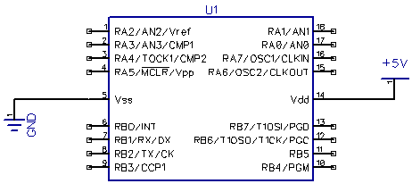
Remain available 16 feet MK. It is not difficult to calculate that the use of each leg by any module reduces the maximum number of digital ports used.
As I wrote in previous articles, I considered the simplest and easiest JAL compiler with IDE JALEdit.
We swing JALPack , we install.
This package contains all the necessary libraries, as well as examples of their use.
Launch JALEdit. We open an example of the program for our microcontroller: 16f628a_blink.jal, in order not to spoil the source, we immediately save it into a new file, for example, 16f628a_test.jal.
All code can be divided into 4 blocks:
By pressing F9 (or the corresponding button), the program will be compiled into a ready-made firmware, and you will see how many resources the MC will use:
If you read the comments, it becomes clear that this program is designed to use external quartz 20MHz.
Since we do not have it yet, we will deal with the configuration and rewrite the program to use the internal generator.
There are different sets of configuration bits in different microprocessors. You can learn about the purpose of each bit in the datasheet (p. 97).
In the connected library, each bit and each value is assigned a readable variable, all that remains is to select the parameters we need.
Change the configuration for yourself:
We modify the program so that the LED blinks only when the button is held down.
Having solved this problem, we will learn how to work with digital ports in both input mode and output mode.
Choose a still unused leg MK. Take, for example, RB5 (pin 11). This leg has no additional functions, so we will not need it anywhere else.
In the digital output mode, the MK can attract either power or earth to the foot.
You can connect the load to both positive and negative. The only difference will be when and in what direction the current flows.
In the first case, the current will flow from the MK when the unit is installed, and in the second, to the MK when the unit is set to zero.
In order for the LED to light up from the logical unit, let’s look at the first option.
To limit the current through the foot (25 mA maximum per digital input or 200 mA on all ports), a current limiting resistor is installed. By the simplest formula, we calculate the minimum value of 125 Ohms. But since we don’t need the limit, take a 500 ohm resistor (or rather the closest one).
To connect a more powerful load, you can use transistors in various versions.
Take the second unused leg anywhere - RB4 (pin 10, the pinout function indicated in the pinout for LVP, which we disabled).
In the digital input mode, the microcontroller can read two states: the presence or absence of voltage. So we need to connect the button so that in one state there is a plus on the foot, and in the second state - the earth is connected to the foot.
In this embodiment, the resistor is used as a pull-up. Usually, a 10 kΩ resistor is used for braces.
You can connect not only the button, the main thing to remember about the current limit through the MC.
Until we forget that we have activated an external reset, we will add a similar button on the leg MCLR (pin 4).
After pressing such a button, the MC will start the program execution from scratch.
We assign variables to our LED and button:
Now, by assigning the led variable to 1 or 0 (on or off, true or false, other aliases ..) we will pull up to the right foot of the MK or plus or minus, thereby turning on and off the LED, and when reading the button variable we will get 1 if the button is not pressed and 0 if the button is pressed.
Now we will write the actions we need in an infinite loop (these actions will be performed continuously. In the absence of an infinite loop, the MC will hang):
The delay is simply:
The frequency of the generator is 4MHz. The operating frequency is 4 times less: 1 MHz. Or 1 clock cycle = 1 μs. 500,000 µs = 0.5 s.
Compile the firmware:
Now we need to write this firmware to the MC, assemble the device according to the diagram and check that everything turned out as it should have.
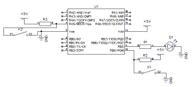
All the same scheme:
We look at the pinout:
We solder ...

We connect to the computer.
Download and run WinPic800 .
Go to Settings-> Hardware , select JDM and the port number on which the programmer hangs
Click Hardware Test , then Detect Device
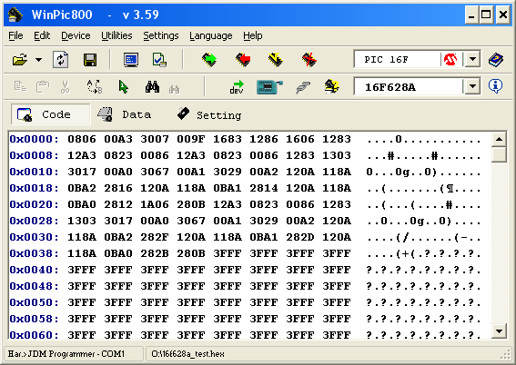
Opening our firmware pic628a_test.hex
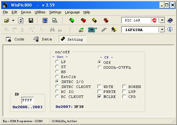
On the Setting tab, you can check that the configuration bits are set correctly, if you wish, you can immediately change them
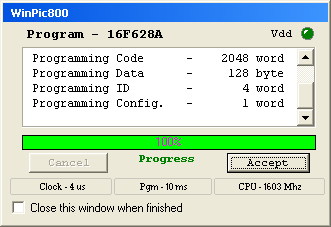
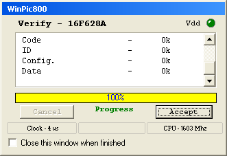
Program All , then Verify All
If there are no errors, continue to solder.
Final scheme:
The button on the MCLR can be soldered as desired, but a tightening is required.
The result of the work can be seen on video.
So, we got the simplest device on the microcontroller: flasher LED.
Now we need to learn how to use the rest of the periphery, but more on that in the next article .
The first step is to download the documentation for the selected microcontroller. Just go to the manufacturer’s website and download the Datasheet .
On the first pages the main characteristics of the MC ( Russian description ) are listed.
')
The main points that we need:
- The microcontroller contains an internal oscillator at 4 MHz, you can also connect an external quartz with a frequency of up to 20 MHz
- 16-foot microcontroller can be used as digital inputs / outputs
- there are 2 analog comparator
- 3 timers
- CCP module
- USART module
- 128 bytes of non-volatile EEPROM memory
The layout of the findings:
Vdd - power.
Vss - land.
This is the minimum required for the work of MK.
Remain available 16 feet MK. It is not difficult to calculate that the use of each leg by any module reduces the maximum number of digital ports used.
Compiler
As I wrote in previous articles, I considered the simplest and easiest JAL compiler with IDE JALEdit.
We swing JALPack , we install.
This package contains all the necessary libraries, as well as examples of their use.
Launch JALEdit. We open an example of the program for our microcontroller: 16f628a_blink.jal, in order not to spoil the source, we immediately save it into a new file, for example, 16f628a_test.jal.
All code can be divided into 4 blocks:
- selection of MK and its configuration
include 16f628a --
--
-- This program assumes a 20 MHz resonator or crystal
-- is connected to pins OSC1 and OSC2.
pragma target clock 20_000_000 -- oscillator frequency
-- configuration memory settings (fuses)
pragma target OSC HS -- HS crystal or resonator
pragma target WDT disabled -- no watchdog
pragma target LVP disabled -- no Low Voltage Programming
pragma target MCLR external -- reset externally
-- - declaration of variables, procedures, functions
alias led is pin_A0
pin_A0_direction = output - making adjustments and calculations before the main loop
enable_digital_io() -- \ - infinite cycle of basic actions of MK
forever loop
led = on
_usec_delay ( 250000 )
led = off
_usec_delay ( 250000 )
end loop
By pressing F9 (or the corresponding button), the program will be compiled into a ready-made firmware, and you will see how many resources the MC will use:
Code: 58/2048 Data: 4/208 Hardware Stack: 0/8 Software Stack: 80
If you read the comments, it becomes clear that this program is designed to use external quartz 20MHz.
Since we do not have it yet, we will deal with the configuration and rewrite the program to use the internal generator.
Configuration
There are different sets of configuration bits in different microprocessors. You can learn about the purpose of each bit in the datasheet (p. 97).
In the connected library, each bit and each value is assigned a readable variable, all that remains is to select the parameters we need.
-- Symbolic Fuse definitions
-- -------------------------
--
-- addr 0x2007
--
pragma fuse_def OSC 0x13 { -- oscillator
RC_CLKOUT = 0x13 -- rc: clkout on ra6/osc2/clkout, rc on ra7/osc1/clkin
RC_NOCLKOUT = 0x12 -- rc: i/o on ra6/osc2/clkout, rc on ra7/osc1/clkin
INTOSC_CLKOUT = 0x11 -- intosc: clkout on ra6/osc2/clkout, i/o on ra7/osc1/clkin
INTOSC_NOCLKOUT = 0x10 -- intosc: i/o on ra6/osc2/clkout, i/o on ra7/osc1/clkin
EC_NOCLKOUT = 0x3 -- ec
HS = 0x2 -- hs
XT = 0x1 -- xt
LP = 0x0 -- lp
}
pragma fuse_def WDT 0x4 { -- watchdog timer
ENABLED = 0x4 -- on
DISABLED = 0x0 -- off
}
pragma fuse_def PWRTE 0x8 { -- power up timer
DISABLED = 0x8 -- disabled
ENABLED = 0x0 -- enabled
}
pragma fuse_def MCLR 0x20 { -- master clear enable
EXTERNAL = 0x20 -- enabled
INTERNAL = 0x0 -- disabled
}
pragma fuse_def BROWNOUT 0x40 { -- brown out detect
ENABLED = 0x40 -- enabled
DISABLED = 0x0 -- disabled
}
pragma fuse_def LVP 0x80 { -- low voltage program
ENABLED = 0x80 -- enabled
DISABLED = 0x0 -- disabled
}
pragma fuse_def CPD 0x100 { -- data ee read protect
DISABLED = 0x100 -- disabled
ENABLED = 0x0 -- enabled
}
pragma fuse_def CP 0x2000 { -- code protect
DISABLED = 0x2000 -- off
ENABLED = 0x0 -- on
}
- OSC - clocking source configuration
can take 8 different values, 4 of which we may need- INTOSC_NOCLKOUT - internal generator (4M Hz)
- HS - external high frequency quartz (8-20 MHz)
- XT = external quartz (200 kHz - 4 MHz)
- LP - external low frequency quartz (up to 200 kHz)
- WDT - Watchdog.
The main work of this timer is to restart the microcontroller when it reaches the end.
In order for a reboot to occur, it must be reset to zero.
Thus, if the timer fails, the timer counter will stop resetting, which will cause the MC to reset. Sometimes it is convenient, but at the moment we will not need it. - PWRTE is a regular timer.
When activated, it will reset the MK until the power rises to the desired level. - BROWNOUT - reset the MK when the power is below normal.
- MCLR - activation of the possibility of external reset MC.
When the function is turned on, the MK will be continuously cut until there is a positive voltage on the leg of the MCLR (pin 4).
To reset the MC it is enough to install a button that closes the pin 4 to the ground. - LVP - activates the possibility of programming at low voltage.
When activated, one digital input will switch to LVP mode (pin 10). If you apply 5V to this leg, the MK will switch to programming mode. For normal operation, MK is required to keep 0V on this leg (connect to ground).
We will use an overvoltage programmer, so LVP is not required to be activated. - CPD - protection of the EEPROM from reading by the programmer.
- CP - protection FLASH (firmware) from reading the programmer.
Change the configuration for yourself:
pragma target clock 4_000_000 -- ,
--
pragma target OSC INTOSC_NOCLKOUT --
pragma target WDT disabled --
pragma target PWRTE disabled --
pragma target MCLR external --
pragma target BROWNOUT disabled --
pragma target LVP disabled --
pragma target CPD disabled -- EEPROM
pragma target CP disabled --
Blink LED at the touch of a button
We modify the program so that the LED blinks only when the button is held down.
Having solved this problem, we will learn how to work with digital ports in both input mode and output mode.
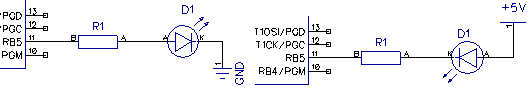
Digital output
Choose a still unused leg MK. Take, for example, RB5 (pin 11). This leg has no additional functions, so we will not need it anywhere else.
In the digital output mode, the MK can attract either power or earth to the foot.
You can connect the load to both positive and negative. The only difference will be when and in what direction the current flows.
In the first case, the current will flow from the MK when the unit is installed, and in the second, to the MK when the unit is set to zero.
In order for the LED to light up from the logical unit, let’s look at the first option.
To limit the current through the foot (25 mA maximum per digital input or 200 mA on all ports), a current limiting resistor is installed. By the simplest formula, we calculate the minimum value of 125 Ohms. But since we don’t need the limit, take a 500 ohm resistor (or rather the closest one).
To connect a more powerful load, you can use transistors in various versions.
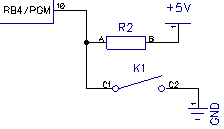
Digital input
Take the second unused leg anywhere - RB4 (pin 10, the pinout function indicated in the pinout for LVP, which we disabled).
In the digital input mode, the microcontroller can read two states: the presence or absence of voltage. So we need to connect the button so that in one state there is a plus on the foot, and in the second state - the earth is connected to the foot.
In this embodiment, the resistor is used as a pull-up. Usually, a 10 kΩ resistor is used for braces.
However, the pull-up resistor is not always necessary. All PORTB legs (RB0-RB7) have an internal tightening programmatically connected. But the use of external braces is much safer.
You can connect not only the button, the main thing to remember about the current limit through the MC.
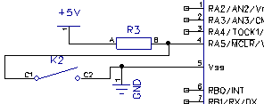
Reset button
Until we forget that we have activated an external reset, we will add a similar button on the leg MCLR (pin 4).
After pressing such a button, the MC will start the program execution from scratch.
Firmware
We assign variables to our LED and button:
enable_digital_io() -- \
--
alias led is pin_B5 -- RB5
pin_B5_direction = output -- RB5
--
alias button is pin_B4 -- RB4
pin_B4_direction = input -- RB4
led = off --
Now, by assigning the led variable to 1 or 0 (on or off, true or false, other aliases ..) we will pull up to the right foot of the MK or plus or minus, thereby turning on and off the LED, and when reading the button variable we will get 1 if the button is not pressed and 0 if the button is pressed.
Now we will write the actions we need in an infinite loop (these actions will be performed continuously. In the absence of an infinite loop, the MC will hang):
forever loop
led = off --
_usec_delay ( 500000 ) -- 0,5
if Button == 0 then -- ,
led = on --
_usec_delay ( 500000 ) -- 0,5
end if
end loop
The delay is simply:
The frequency of the generator is 4MHz. The operating frequency is 4 times less: 1 MHz. Or 1 clock cycle = 1 μs. 500,000 µs = 0.5 s.
Compile the firmware:
Errors: 0 Warnings: 0
Code: 60/2048 Data: 4/208 Hardware Stack: 0/8 Software Stack: 80
Now we need to write this firmware to the MC, assemble the device according to the diagram and check that everything turned out as it should have.
Programmer
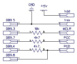
All the same scheme:
We look at the pinout:
- PGD - pin 13
- PGC - pin 12
- MCLR (Vpp) - pin 4
- Vdd - pin 14
- Vss - pin 5
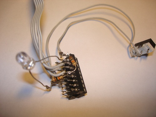
We solder ...
Poor-quality soldering is one of the main problems of the device’s inoperability.
Do not repeat my bad habits: do not use mounted installation.
In this case, the tail from the old PS / 2 mouse inserted into the mouse connector was used as the 5V power supply.
We connect to the computer.
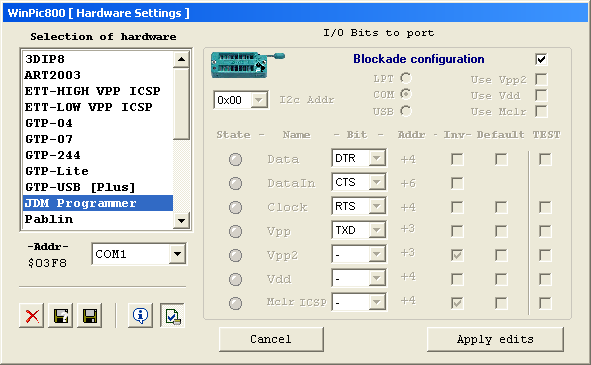
Download and run WinPic800 .
Go to Settings-> Hardware , select JDM and the port number on which the programmer hangs
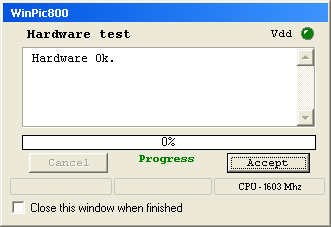
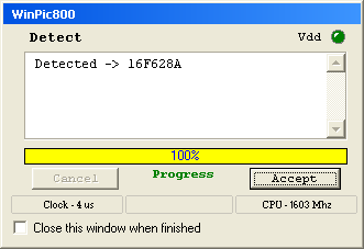
Click Hardware Test , then Detect Device
Opening our firmware pic628a_test.hex
On the Setting tab, you can check that the configuration bits are set correctly, if you wish, you can immediately change them
Program All , then Verify All
If there are no errors, continue to solder.
Result
Final scheme:
From the programmer, only the high voltage (12V) on the MCLR prevents us. In order not to solder the entire programmer, you can only solder one wire ... Or simply do not connect the programmer to the COM port. The rest of the wires will not disturb us (and the connected power and ground will only simplify the soldering).
The button on the MCLR can be soldered as desired, but a tightening is required.
When you re-connect the programmer, the resistor will need to be removed, otherwise it will pull 12v to power.
The result of the work can be seen on video.
So, we got the simplest device on the microcontroller: flasher LED.
Now we need to learn how to use the rest of the periphery, but more on that in the next article .
Source: https://habr.com/ru/post/97795/
All Articles