Programming the PIC16F876A. We collect the circuit with a smoothly flashing LED
 This article is aimed at newcomers to Microchip PIC16 microcontroller programming. In our case, I chose a slightly superior microcontroller for such tasks, namely the PIC16F876A. Microcontroller programming will be done in MPLAB IDE .
The purpose of the work: to assemble a circuit that will flash the LED, attention, using PWM .
And so, the purpose of the task outlined. We now turn to the implementation of our plans.
Part 1. Iron.
First of all, we need components, from which we will assemble the circuit. Namely:
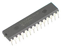
- PIC16F876A microcontroller
- Crumbly to it
- Light-emitting diode
- Bread board
Development board is desirable to have in stock.
The concept of “crumbling” includes such details as: a pair of capacitors for quartz and a capacitor at the output of the CPP module (In order to smooth out the pulsations).
')
The assembled circuit is as follows:

This is a typical inclusion of the microcontroller, I did not invent anything new here.
Also, for programming the microcontroller, I use the ICD2 debugger programmer. It connects to a computer via USB and works great on both Windows and GNU / Linux. In our case, we will use the native MPLAB IDE in Windows.
Screen in progress:

Part 2. Software.
The LED is connected to the 1st CPP module (PWM). The register CPP1CON is responsible for setting the module in the microcontroller. In order for the module to work, we first need to initialize the timer. For PWM mode, the timer TMR2 is used . For its configuration is responsible register T2CON . Initialization:
movlw .0
bcf STATUS, 5

movwf T2CON ; T2CON - 0
bsf T2CON, 0 ; T2CKPS0 ()
bsf T2CON, 2 ; TMR2 TMR2ON
bsf T2CON, 3 ; TOUTPS0 ()
At this point, the timer initialization is completed. Now, when the controller is turned on, it will serve as the source for our PWM module.
Initialization of the PWM module is as follows:
movlw 00101111b ;
movwf CPPCON ;
bsf CPPCON, 2 ;
The full source of the program for the firmware of our microcontroller:
STATUS equ 03h
TRISC equ 07h
CPPCON equ 17h
CPP1L equ 15h
T2CON equ 12h
counter equ 23h
tmp equ 25h
org 0
goto start
start
bsf STATUS, 5

movlw .0
movwf TRISC
bcf STATUS, 5
movwf T2CON
bsf T2CON, 0
bsf T2CON, 2
bsf T2CON, 3
movlw 00101111b
movwf CPPCON
bsf CPPCON, 2
movlw .0
movwf CPP1L
movlw .255
movwf tmp
decfsz tmp, 1
goto $+2
goto $+4
call delay10mS
incf CPP1L, 1
goto $-5
movlw .255
movwf tmp
decfsz tmp, 1
goto $+2
goto $+4
call delay10mS
decf CPP1L, 1
goto $-5
goto $-16
delay10mS
movlw .50
movwf counter
loop
call delay200uS
decfsz counter
goto loop
return
delay200uS
movlw .100
addlw -1
btfss STATUS,2
goto $-2
return
end
equ - Assign a name to a specific address.
goto - Move a program to a label, or a specific string.
call - subroutine call
movlw - Put in register W, number
movwf - Move a number from register W
bsf - Set the bit in the register to state 1
bcf - Set the bit in the register to 0
addlw - Add a number to the register W
btfss - Check bit in register for 1
incf - Incriminate the register (add 1)
decf - De -register register (subtract 1)
decfsz - Subtract 1 from register + check for 0
Delays in the program are calibrated to a quartz resonator frequency of 8 MHz.
The principle of the program.
In the beginning, the registers are initialized, then the internal microcontroller modules are configured.
In the variable tmp we can set the duty cycle, thereby changing the maximum brightness of the LED.
Next, a part of the program is implemented that is responsible for the LED blinking itself, taking into account the use of PWM. First, by incriminating the CPP1L to the tmp value, we make the LED slowly start to glow, and then we do the reverse operation.
Part 3. Final
Before flashing your controller, you need to set the microcontroller configuration bits. Without them, nothing will work.
So:
1) WDT - turn off. This is a watchdog timer. Designed for hardware reset of the microcontroller at the time of an unexpected hang.
2) LWP - turn off. This is low voltage programming. We use a normal programmer that feeds on the MCLR 13B.
3) Oscillator: In this case, we have 8 MHz. So set the value of XT.
Part 4. Bonus.
Video for those who have not yet programmed / did not collect the scheme, but really wants to see the result:
Part 5. Information.
Official microchip website - www.microchip.com
Cited sources - www.wikipedia.org
Russian documentation for PIC microcontrollers - www.microchip.ru/lit/?mid=1x0
Source: https://habr.com/ru/post/97703/
All Articles