Create a simple usb device to communicate with your program
In continuation of the topic of creating your own USB gadget.
Creating a simple device.
Once the device is planned to be connected to a PC, then the data transfer between the device and the PC will most likely be required.
Let's start writing firmware and software, having established a connection between them.
The simplest data transfer option is to use a class of USB communication devices (CDC).
With such a connection, the device will be visible in the system as a normal virtual COM port.
The advantage of this connection is the lack of need to write your own drivers.
The ease of receiving and transmitting data is also pleasing: to work with a port in Windows, it is enough to open it as a text file and perform normal read / write operations.
Take a scheme with minimal strapping MK.
')
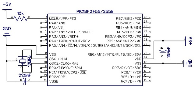
This time we need to add only 4 contacts to USB and one button (the button is needed only for the bootloader: it’s much easier to press it and replace the firmware in the device via USB rather than rearrange the chip in the programmer).

Not trying hard to make it beautiful, the layout may look like this:

But if you want to frequently experiment with the connected components, it is better to immediately separate each leg of the MK by making an analogue of arduino - Jaluino .
Let's start with a minimum:
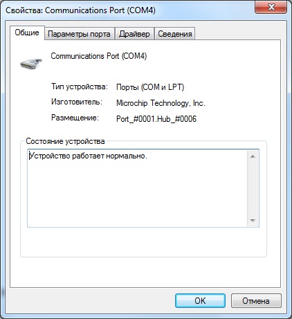
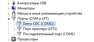
Compiling this code, writing the received HEX file to the MC using a bootloader and launching the device, you can see how the new device is defined in the system: Virtual com-port.
Now that the device is already working, let's teach it to communicate.
To read the received byte there is a function usb_serial_read ( byte ) : boolean. If there is a received byte, it puts it into the specified variable and returns true , otherwise it returns false .
To send a byte, there is a usb_serial_data procedure. It is disguised as a variable, so to send a byte, it is enough to assign the value of the sent byte to it.
We declare a variable in bytes up to the main loop, in the main loop we will check for the presence of received bytes, and, if there are any, send them back.
We compile, hold down the button, distort the power, launch the bootloader, change the firmware, run.
The device was again defined in the system, now we need software in order to test the operation of the device.
While we do not have our own, we use a ready-made terminal: I used the RealTerm program.
Open the port with the desired number and send the data.
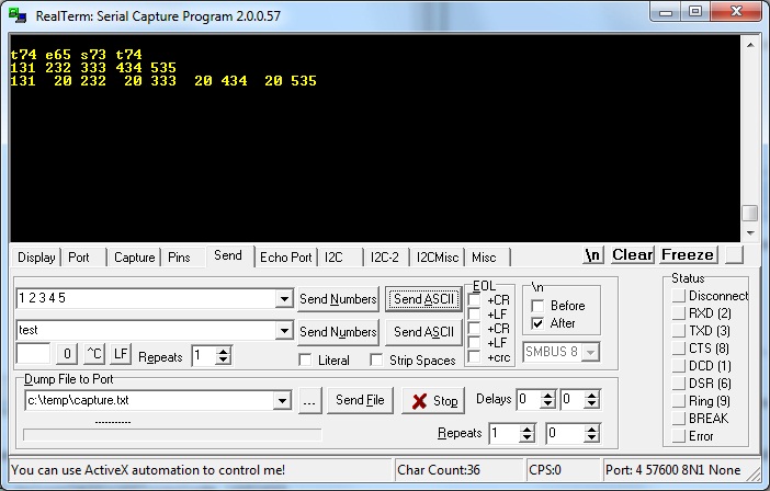
And in response we receive what we sent. So everything works as it should.
So, our microcontroller is able to receive bytes and immediately send them back. Now we will write our software to communicate with it (I will use Delphi).
We create a new project, scatter the necessary components in shape:
SpinEdit1 - to specify the port number
Button1 - to establish a connection
Button2 - to break the connection
SpinEdit2 - to enter byte in decimal
Button3 - to send bytes
Memo1 - to display the received information.
As mentioned above, you need to work with the com port in the same way as with a regular text file: using the CreateFile, WriteFile and ReadFile functions.
In order not to go into details, let's take a ready-made library for working with a com port: ComPort.
We hang on each button the necessary task and get the final code:
We start, we establish connection, we send bytes:

So our simplest terminal is ready to work with the simplest usb device.
As you can see, reading and writing occurs by dynamic arrays of bytes.
Processing the received information, you can create the necessary exchange protocol suitable for the current task.
If you dwell on this, you will get an ordinary article with a detailed description of the example of using the library, of which there is enough in the open spaces of the network. Because add a little more in-depth information.
Sending information one byte is not always convenient. Very often the print library can be useful. It contains procedures for sending data of all possible lengths in various formats: byte, hex, dec, bin, boolean, which can simplify data output in the program.
The name of all commands can be viewed in the library file.
If before starting the main cycle of the microcontroller, you must first establish a connection with a PC, you can add lines before it
If you leave everything as it is, the system with each new connection will allocate the first free port number. This means that it will always have to follow.
To prevent this from happening, the device must be assigned a unique serial number value before connecting the usb library:
The number can be of any length and contain different characters.
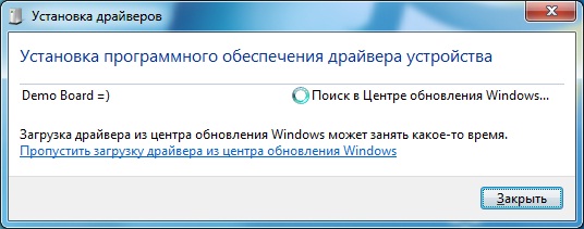
You can change the device name that is visible in the system before installing the drivers by declaring an array with the name, like the serial number, this must be done before connecting the USB library.
But alas, after installing the drivers, the device will change the name to the one specified in the .inf file, therefore we will change the name and there
Alas, there are no direct ways to accomplish this task, so you have to fake it.
First of all, you need to assign a unique manufacturer and product value to your device in order to easily identify it among hundreds of other standard CDC firmware.
VID and PID are issued for denyuzhku, so let's go on the way of the Chinese: quietly take for yourself the obviously free values.
Firmware:
In the firmware, you must declare two variables before connecting the USB library
Instead of FF10, you can insert any two words (2 bytes). The end result is contained in the attached archive.
Drivers:
Since drivers are not designed for our combination of VID and PID, we will add our values to the .inf file manually:
Soft:
To catch device connection / disconnect events, we will connect the ComponentUSB library. I do not consider it necessary to explain each line: all changes can be seen in the attached project.
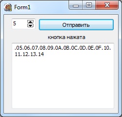
It is difficult to make out in the screenshot, but the send button is active only when there is a connected device, and every 50ms the program sends a request to get the button state (which, however, is wrong, because pressing the button should be processed on the MC).
As you can see, organizing data exchange between a PC and a PC via USB is not the most difficult task. The resulting connection can be used not only for finite purposes: it is also suitable for debugging the program. After all, sending the results of calculations to a computer, the current state of the registers and variables is much clearer than blinking a pair of LEDs in Morse code.
And finally: I advise you to look into the source code of the mood lamp. There you can find quite a good option for processing the received data to organize a convenient exchange protocol.
PS
Project files .
Creating a simple device.
Once the device is planned to be connected to a PC, then the data transfer between the device and the PC will most likely be required.
Let's start writing firmware and software, having established a connection between them.
The simplest data transfer option is to use a class of USB communication devices (CDC).
With such a connection, the device will be visible in the system as a normal virtual COM port.
The advantage of this connection is the lack of need to write your own drivers.
The ease of receiving and transmitting data is also pleasing: to work with a port in Windows, it is enough to open it as a text file and perform normal read / write operations.
Iron.
Take a scheme with minimal strapping MK.
')
This time we need to add only 4 contacts to USB and one button (the button is needed only for the bootloader: it’s much easier to press it and replace the firmware in the device via USB rather than rearrange the chip in the programmer).
Not trying hard to make it beautiful, the layout may look like this:
But if you want to frequently experiment with the connected components, it is better to immediately separate each leg of the MK by making an analogue of arduino - Jaluino .
Firmware
Let's start with a minimum:
include 18f2455 --
--
enable_digital_io () --
--
alias Button is pin_B7 -- ,
pin_B7_direction = input --
--
-- - USB CDC
include usb_serial -- usb
--
usb_serial_init () -- -- USB CDC
forever loop -- ,
usb_serial_flush () -- usb.
--
end loop
Compiling this code, writing the received HEX file to the MC using a bootloader and launching the device, you can see how the new device is defined in the system: Virtual com-port.
Now that the device is already working, let's teach it to communicate.
To read the received byte there is a function usb_serial_read ( byte ) : boolean. If there is a received byte, it puts it into the specified variable and returns true , otherwise it returns false .
To send a byte, there is a usb_serial_data procedure. It is disguised as a variable, so to send a byte, it is enough to assign the value of the sent byte to it.
We declare a variable in bytes up to the main loop, in the main loop we will check for the presence of received bytes, and, if there are any, send them back.
include 18f2455
--
enable_digital_io ()
--
alias Button is pin_B7
pin_B7_direction = input
--
--
include usb_serial
--
usb_serial_init ()
var byte ch --
forever loop --
usb_serial_flush ()
if ( usb_serial_read ( ch ) ) then -- , ch
usb_serial_data = ch --
end if
end loop
We compile, hold down the button, distort the power, launch the bootloader, change the firmware, run.
The device was again defined in the system, now we need software in order to test the operation of the device.
While we do not have our own, we use a ready-made terminal: I used the RealTerm program.
Open the port with the desired number and send the data.
And in response we receive what we sent. So everything works as it should.
Soft
So, our microcontroller is able to receive bytes and immediately send them back. Now we will write our software to communicate with it (I will use Delphi).
We create a new project, scatter the necessary components in shape:
SpinEdit1 - to specify the port number
Button1 - to establish a connection
Button2 - to break the connection
SpinEdit2 - to enter byte in decimal
Button3 - to send bytes
Memo1 - to display the received information.
As mentioned above, you need to work with the com port in the same way as with a regular text file: using the CreateFile, WriteFile and ReadFile functions.
In order not to go into details, let's take a ready-made library for working with a com port: ComPort.
We hang on each button the necessary task and get the final code:
unit Unit1;

interface

uses
Windows, Messages, SysUtils, Variants, Classes, Graphics , Controls, Forms,
Dialogs, StdCtrls, Spin,ComPort;

type
TForm1 = class (TForm)
SpinEdit1: TSpinEdit;
Button1: TButton;
Button2: TButton;
SpinEdit2: TSpinEdit;
Button3: TButton;
Memo1: TMemo;
procedure OnRead(Sender: TObject; ReadBytes: array of Byte );
procedure Button1Click(Sender: TObject);
procedure Button2Click(Sender: TObject);
procedure FormDestroy(Sender: TObject);
procedure Button3Click(Sender: TObject);
private
{ Private declarations }
Port: TComPort;
public
{ Public declarations }
end;

var
Form1: TForm1;
num: integer;
implementation

{$R *.dfm}

procedure TForm1.Button1Click(Sender: TObject);
begin
Port := TComPort.Create(SpinEdit1.Value, br115200); //
Port.OnRead := OnRead; //
Button2.Enabled := true ; //
end;

procedure TForm1.Button2Click(Sender: TObject);
begin
Port.Free; //
Button2.Enabled := false ; //
end;

procedure TForm1.Button3Click(Sender: TObject);
begin
if Button2.Enabled then Port.Write([SpinEdit2.Value]);
end;

procedure TForm1.FormDestroy(Sender: TObject);
begin
if Button2.Enabled then
Port.Free;
end;

procedure TForm1.OnRead(Sender: TObject; ReadBytes: array of Byte );
var
i:integer;
begin
for i := Low(ReadBytes) to High(ReadBytes) do //
begin
Memo1.Text := Memo1.Text + '.' +InttoHex(ReadBytes[i],2); // HEX
inc(num); // -
end;
if num > 10 then begin
Memo1.Lines.Add( '' ); //
num := 0;
end;
end;

end.
We start, we establish connection, we send bytes:
So our simplest terminal is ready to work with the simplest usb device.
As you can see, reading and writing occurs by dynamic arrays of bytes.
Processing the received information, you can create the necessary exchange protocol suitable for the current task.
include 18f2455
--
enable_digital_io ()
--
alias Button is pin_B7
pin_B7_direction = input
--
--
include usb_serial
--
usb_serial_init ()
var byte ch
var byte i --
forever loop --
usb_serial_flush ()
if ( usb_serial_read ( ch ) ) then --
case ch of --
0 : usb_serial_data = 0xff
1 : usb_serial_data = Button --
OTHERWISE block -- -
for 16 using i loop -- 10
usb_serial_data = ch + i -- ch ch+15
end loop
end block
end case
end if
end loop
Additional features
If you dwell on this, you will get an ordinary article with a detailed description of the example of using the library, of which there is enough in the open spaces of the network. Because add a little more in-depth information.
Simplify data submission
Sending information one byte is not always convenient. Very often the print library can be useful. It contains procedures for sending data of all possible lengths in various formats: byte, hex, dec, bin, boolean, which can simplify data output in the program.
> include print
...
var dword data
print_dword_hex ( usb_serial_data , data )
The name of all commands can be viewed in the library file.
Waiting for PC connection
If before starting the main cycle of the microcontroller, you must first establish a connection with a PC, you can add lines before it
while ( usb_cdc_line_status () == 0x00 ) loop
end loop
We bind to the device port number
If you leave everything as it is, the system with each new connection will allocate the first free port number. This means that it will always have to follow.
To prevent this from happening, the device must be assigned a unique serial number value before connecting the usb library:
The number can be of any length and contain different characters.
const byte USB_STRING3 [ 24 ] =
{
24 , --
0x03 , -- bDescriptorType
"0" , 0x00 ,
"1" , 0x00 ,
"2" , 0x00 ,
"3" , 0x00 ,
"4" , 0x00 ,
"5" , 0x00 ,
"6" , 0x00 ,
"7" , 0x00 ,
"8" , 0x00 ,
"9" , 0x00 ,
"X" , 0x00
}
Change the device name to your
You can change the device name that is visible in the system before installing the drivers by declaring an array with the name, like the serial number, this must be done before connecting the USB library.
const byte USB_STRING2 [ 28 ] =
{
28 , --
0x03 , -- bDescriptorType
"D" , 0x00 ,
"e" , 0x00 ,
"m" , 0x00 ,
"o" , 0x00 ,
" " , 0x00 ,
"B" , 0x00 ,
"o" , 0x00 ,
"a" , 0x00 ,
"r" , 0x00 ,
"d" , 0x00 ,
" " , 0x00 ,
"=" , 0x00 ,
")" , 0x00
}
But alas, after installing the drivers, the device will change the name to the one specified in the .inf file, therefore we will change the name and there
[Strings]
DESCRIPTION = "Demo CDC"
Let's organize autoconnection of the device
Alas, there are no direct ways to accomplish this task, so you have to fake it.
First of all, you need to assign a unique manufacturer and product value to your device in order to easily identify it among hundreds of other standard CDC firmware.
VID and PID are issued for denyuzhku, so let's go on the way of the Chinese: quietly take for yourself the obviously free values.
Firmware:
In the firmware, you must declare two variables before connecting the USB library
const word USB_SERIAL_PRODUCT_ID = 0xFF10
const word USB_SERIAL_VENDOR_ID = 0xFF10
Instead of FF10, you can insert any two words (2 bytes). The end result is contained in the attached archive.
Drivers:
Since drivers are not designed for our combination of VID and PID, we will add our values to the .inf file manually:
[DeviceList]
% DESCRIPTION% = DriverInstall, USB \ VID_FF10 & PID_FF10
[DeviceList.NTamd64]
% DESCRIPTION% = DriverInstall, USB \ VID_FF10 & PID_FF10
Soft:
To catch device connection / disconnect events, we will connect the ComponentUSB library. I do not consider it necessary to explain each line: all changes can be seen in the attached project.
Result
It is difficult to make out in the screenshot, but the send button is active only when there is a connected device, and every 50ms the program sends a request to get the button state (which, however, is wrong, because pressing the button should be processed on the MC).
As you can see, organizing data exchange between a PC and a PC via USB is not the most difficult task. The resulting connection can be used not only for finite purposes: it is also suitable for debugging the program. After all, sending the results of calculations to a computer, the current state of the registers and variables is much clearer than blinking a pair of LEDs in Morse code.
And finally: I advise you to look into the source code of the mood lamp. There you can find quite a good option for processing the received data to organize a convenient exchange protocol.
PS
Project files .
Source: https://habr.com/ru/post/95925/
All Articles