Creating a USB gadget from scratch or another mood lamp
Somehow came across an article about the mood lamp . Being very far from electrical engineering and completely unfamiliar with the principle of operation of microcontrollers, the data obtained from the topic top was not enough to understand all the necessary actions to create a lamp. Over time, I came across other interesting projects on microcontrollers, because at one point there was a desire to spend some of my free time to conquer this element.
In this article, I tried to collect information about the first steps of creating a project from scratch on a microcontroller.
I decided to study the work of microcontrollers in practice: doing something real is much more interesting than driving a dozen LEDs in a simulator.
First of all, it was necessary to decide what I wanted to do. I stopped at the aforementioned mood lamp. In order not to create a complete analog, it was decided to expand the functionality of the lamp and add control from a PC.
The choice of microcontroller was simple.
Working with a PC through the COM port is incompatible, because the USB connection option was chosen. In order not to start with micro-soldering, it was decided to use only the components in the DIP package. There are few suitable microcontrollers left: either any AVR with software USB emulation, or a PIC 18F series with hardware support for USB 2.0.
Someone may decide differently, but my choice fell on the last option, in this project I used the PIC18F2455 MC.
')
The simplest scheme for connecting the PIC18F2455 is as follows:
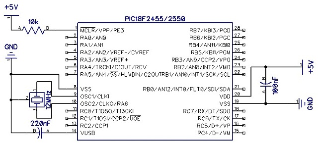
For some reason unknown to me, 25 and 26 legs of the MK are interchanged in the diagram.
Making a start from it it is possible to make the scheme for a lamp. Of the changes required:
Power 5V and ground take from USB.
Connect D + and D- USB with the corresponding legs of the MK.
Connect to one digital input button.
Connect three transistors to the three digital outputs to control the LED.
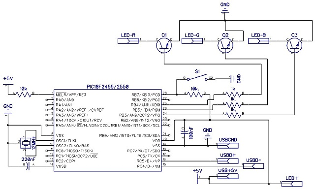
The diagram does not display only the power resistors to the cathodes of the LED.
Before assembling the microcontroller must be flashed. Smart people will say that there is nothing better than PicKit for flashing peaks. But who wants to spend 1000-2000 rubles. for one-time firmware MK?
There are many self-made programmers circuits of varying complexity of execution, but not all of them come out to make them work the first time.
I have tried two of the most simple programmer: one works through the LPT port, the other through COM. Surprisingly, it all worked without any problems.
Scheme art2003 ( read more ):
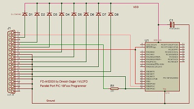
LPT connector, 8 diodes, capacitor and resistor. Only the list of supported MK not happy.
Diagram of a universal programmer (works like JDM):
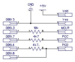
With such a simple circuit on three resistors with an external 5V power supply, you can flash almost any PIC, the main thing is to connect the wires to the proper legs of the MK (and also not to forget that there can be several Vdd and Vss).
5V power can be taken from USB, computer power supply or charger for the phone.
Both programmers are supported by the peak firmware program - WinPic800.
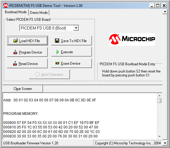
The programmer is good, but what if you need to frequently reflash the MC, do not leave access to the board for the sake of such trifles? In this case, the use of a bootloader is well suited. It is enough to write it in the MC once, after which all firmware updates should be performed directly from the computer via USB.
At the initial stage it is not required to know the details, it is enough to use ready-made solutions. After flashing the bootloader in the MC, it is enough to energize while the button is held down - and the system will detect a new Microchip Custom USB Device. After installing the drivers, you can safely work with available memory through the software distributed by Microchip.
There are many good compilers, I stopped my choice, probably on the most little known - JAL ( Just Another Language ). Perhaps someone will consider using this compiler unreasonable, but it completely covered all my requirements for starting. The minimum size (archive 11 mb), lack of installation (1 minute for unpacking does not count), no frills (I do not need a development environment), availability of all necessary libraries, working examples for each MC (flashing LED) and for all basic functionalities.
Sample LED blinking code:
When using a bootloader, the entire MK configuration is installed in it, to adapt the firmware to the bootloader, it is enough to change the compilation parameters by adding the -loader18 2048 -no-fuse flags.
Describing all the details when writing a program for MC - not only one article, but also a book is not enough. The PIC18F2455 / 2550/4455/4550 documentation alone takes 430 pages. Finding everything at once is almost impossible.
The easiest way to write something of your own is to see examples and do it by analogy. This path is not always the most correct, but constantly checking every line of code for working capacity is quite a working program.
Functionality included in the current firmware version:
It would seem: like nothing special. For the evening you can write. But, not knowing how the MK, you collect, probably, almost all the rakes that can be found. Nevertheless, all the work on re-reading the documentation, in-depth google and rewriting the code from scratch was justified: the end result turned out to be quite workable.
The main components of the lamp - housing, microcontroller and LED.
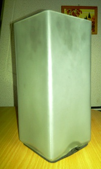
As a basis for the lamp, the same GRÖNÖ lamp from IKEA was taken.
LED - Chinese analogue with DealExtreme ( SKU 4530 ), almost 3 times cheaper than the original.
The LED is very hot, you need at least some radiator, otherwise it will not burn brightly for long.
Small things:
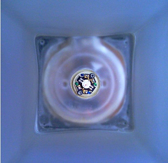
All this is placed on the board in order to get into the niche of the lamp.
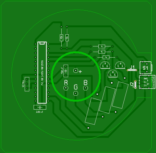
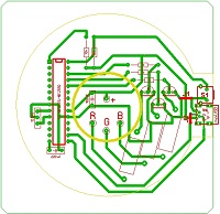
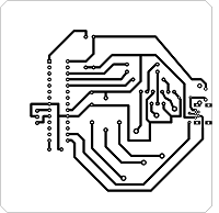
PCB layout in Sprint Layout, translation into PCB by LUT method, drilling, soldering.
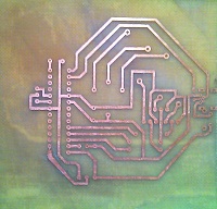
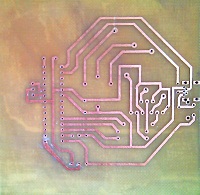
The work is not perfect, and it was not without errors: one resistor turned out to be superfluous (it is no longer on the diagrams).
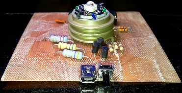
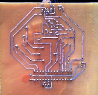
The entire board is placed under the lamp, in the recess for the wire there is a button and a miniUSB connector for power and communication with the PC.
Power is supplied via miniUSB, but you should not connect a lamp with such an LED to the first power source turned on: the lamp consumes slightly less than 1A at full brightness. Not all power supplies are designed for such a current, depending on the type of power supply, they can become extremely bad, which can lead to unpleasant consequences.
To connect to a computer, you may need a cable with an additional power connector (like portable HDD) or a good active USB hub.
Finding the right software for an individual task is impossible. I had to deal with this issue myself.
The program was written in parallel with the firmware and was mainly used to debug the lamp. At the moment, several functions are not implemented - but perhaps there will soon be time to complete them.
As it turned out, making yourself a unique USB gadget from scratch is an affordable task. It does not require the skill of soldering expensive ft232, it does not need to be distracted by compatibility with the software implementation of USB and does not require any semi-finished Arduino. All you need is a little desire.
A set of project files.
PIC 18F family documentation with USB 2.0 support.
Russian translation of documentation: the book Microchip Microcontrollers with USB Hardware Support Author: V. S. Yatsenkov.
A set of libraries for JAL and IDE - JALEdit .
WinPic800 - program for firmware Pic.
MCHPFSUSB - a set to work with the bootloader.
In this article, I tried to collect information about the first steps of creating a project from scratch on a microcontroller.
purpose
I decided to study the work of microcontrollers in practice: doing something real is much more interesting than driving a dozen LEDs in a simulator.
First of all, it was necessary to decide what I wanted to do. I stopped at the aforementioned mood lamp. In order not to create a complete analog, it was decided to expand the functionality of the lamp and add control from a PC.
Microcontroller
The choice of microcontroller was simple.
Working with a PC through the COM port is incompatible, because the USB connection option was chosen. In order not to start with micro-soldering, it was decided to use only the components in the DIP package. There are few suitable microcontrollers left: either any AVR with software USB emulation, or a PIC 18F series with hardware support for USB 2.0.
Someone may decide differently, but my choice fell on the last option, in this project I used the PIC18F2455 MC.
18F2455 can be replaced without consequences on 18F2550, the difference is only in the amount of memory.
With minimal changes, you can also use:
18F4455 / 4550 - if you need more legs (40 instead of 28)
18F14K50 - 20 legs, slightly trimmed functionality, but a bit cheaper
')
Scheme
The simplest scheme for connecting the PIC18F2455 is as follows:
For some reason unknown to me, 25 and 26 legs of the MK are interchanged in the diagram.
Making a start from it it is possible to make the scheme for a lamp. Of the changes required:
Power 5V and ground take from USB.
Connect D + and D- USB with the corresponding legs of the MK.
Connect to one digital input button.
Connect three transistors to the three digital outputs to control the LED.
The diagram does not display only the power resistors to the cathodes of the LED.
Programmer
Before assembling the microcontroller must be flashed. Smart people will say that there is nothing better than PicKit for flashing peaks. But who wants to spend 1000-2000 rubles. for one-time firmware MK?
There are many self-made programmers circuits of varying complexity of execution, but not all of them come out to make them work the first time.
I have tried two of the most simple programmer: one works through the LPT port, the other through COM. Surprisingly, it all worked without any problems.
Scheme art2003 ( read more ):
LPT connector, 8 diodes, capacitor and resistor. Only the list of supported MK not happy.
Diagram of a universal programmer (works like JDM):
With such a simple circuit on three resistors with an external 5V power supply, you can flash almost any PIC, the main thing is to connect the wires to the proper legs of the MK (and also not to forget that there can be several Vdd and Vss).
5V power can be taken from USB, computer power supply or charger for the phone.
Both programmers are supported by the peak firmware program - WinPic800.
Bootloader
The programmer is good, but what if you need to frequently reflash the MC, do not leave access to the board for the sake of such trifles? In this case, the use of a bootloader is well suited. It is enough to write it in the MC once, after which all firmware updates should be performed directly from the computer via USB.
At the initial stage it is not required to know the details, it is enough to use ready-made solutions. After flashing the bootloader in the MC, it is enough to energize while the button is held down - and the system will detect a new Microchip Custom USB Device. After installing the drivers, you can safely work with available memory through the software distributed by Microchip.
Compiler
There are many good compilers, I stopped my choice, probably on the most little known - JAL ( Just Another Language ). Perhaps someone will consider using this compiler unreasonable, but it completely covered all my requirements for starting. The minimum size (archive 11 mb), lack of installation (1 minute for unpacking does not count), no frills (I do not need a development environment), availability of all necessary libraries, working examples for each MC (flashing LED) and for all basic functionalities.
Sample LED blinking code:
include 18f2455 --
--
pragma target clock 48_000_000 -- ,
--
enable_digital_io () --
--
alias led is pin_B3 -- led B3
pin_B3_direction = output -- B3
--

forever loop --
led = on --
_usec_delay ( 250000 ) --
led = off --
_usec_delay ( 250000 ) --
end loop
When using a bootloader, the entire MK configuration is installed in it, to adapt the firmware to the bootloader, it is enough to change the compilation parameters by adding the -loader18 2048 -no-fuse flags.
Firmware
Describing all the details when writing a program for MC - not only one article, but also a book is not enough. The PIC18F2455 / 2550/4455/4550 documentation alone takes 430 pages. Finding everything at once is almost impossible.
The easiest way to write something of your own is to see examples and do it by analogy. This path is not always the most correct, but constantly checking every line of code for working capacity is quite a working program.
Functionality included in the current firmware version:
- software 8-bit PWM at 200 Hz, 3 channels
- the possibility of using the gamma correction table (it is desirable to translate PWM to BAM 10-bit, otherwise color transitions are noticeable)
- 4 procedures for working with color:
- software timer with 0.1 s increments (max. time 1: 49: 13.5) for pauses and setting the transition time
- transition from the current to the specified color by RGB values during the timer
- transition from the current to the specified color by HSV values during the timer
- instant color change
- 6 color change routines
- rotation on the HSV wheel; in addition: fluctuation in saturation and brightness
- cycle of primary colors; in addition: random time of transition to each step
- fixed color; optional: second fixed color
- random color by RGB parameters; optional: random color according to HSV parameters
- predefined color cycle; in addition: - (in the future - a set of commands downloaded from a PC)
- (activated from PC) direct output of color received from PC; in addition: smooth transition to the new color
- three-mode button
- quick press - subroutine change (or pause reset);
- long press - an alternative mode;
- long press - switch to the service mode (for flashing)
- countdown timer (set from PC, max. time 1: 49: 13.5)
- event notification (multiple and one-time), 6 channels (by the number of primary colors)
- pause for various events
- PC connection:
- opportunity to change the basic parameters of each subroutine using software
- Receive countdown timer and alert control commands
- the ability to directly control the color from the PC, which opens the way to expanding the functionality through software.
It would seem: like nothing special. For the evening you can write. But, not knowing how the MK, you collect, probably, almost all the rakes that can be found. Nevertheless, all the work on re-reading the documentation, in-depth google and rewriting the code from scratch was justified: the end result turned out to be quite workable.
Assembly
The main components of the lamp - housing, microcontroller and LED.
As a basis for the lamp, the same GRÖNÖ lamp from IKEA was taken.
LED - Chinese analogue with DealExtreme ( SKU 4530 ), almost 3 times cheaper than the original.
The LED is very hot, you need at least some radiator, otherwise it will not burn brightly for long.
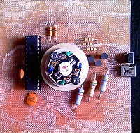
Small things:
- socket for MK
- 3 transistors
- 3 powerful and 5 low-power resistors
- 2 capacitors
- resonator
- button
- miniUSB connector (rare in DIP version)
All this is placed on the board in order to get into the niche of the lamp.
PCB layout in Sprint Layout, translation into PCB by LUT method, drilling, soldering.
The work is not perfect, and it was not without errors: one resistor turned out to be superfluous (it is no longer on the diagrams).
The entire board is placed under the lamp, in the recess for the wire there is a button and a miniUSB connector for power and communication with the PC.
Power is supplied via miniUSB, but you should not connect a lamp with such an LED to the first power source turned on: the lamp consumes slightly less than 1A at full brightness. Not all power supplies are designed for such a current, depending on the type of power supply, they can become extremely bad, which can lead to unpleasant consequences.
To connect to a computer, you may need a cable with an additional power connector (like portable HDD) or a good active USB hub.
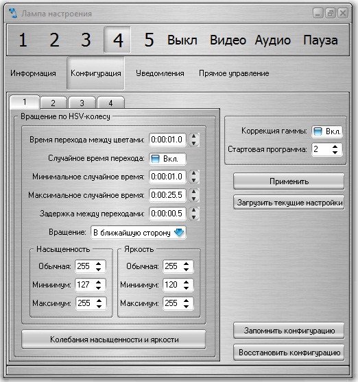
Soft
Finding the right software for an individual task is impossible. I had to deal with this issue myself.
The program was written in parallel with the firmware and was mainly used to debug the lamp. At the moment, several functions are not implemented - but perhaps there will soon be time to complete them.
Results
As it turned out, making yourself a unique USB gadget from scratch is an affordable task. It does not require the skill of soldering expensive ft232, it does not need to be distracted by compatibility with the software implementation of USB and does not require any semi-finished Arduino. All you need is a little desire.
Useful information
A set of project files.
PIC 18F family documentation with USB 2.0 support.
Russian translation of documentation: the book Microchip Microcontrollers with USB Hardware Support Author: V. S. Yatsenkov.
A set of libraries for JAL and IDE - JALEdit .
WinPic800 - program for firmware Pic.
MCHPFSUSB - a set to work with the bootloader.
Source: https://habr.com/ru/post/95789/
All Articles