Automation of temperature measurements using the ADC board
 We all measured temperature at least once in our lives. Whether at least your own body, even the air outside the window or the processor in the motherboard. In most cases, in everyday life we are talking about the range of -50 ... 100 º, and a simple alcohol thermometer is suitable for such measurements. In the case of a processor, a semiconductor sensor is used, but it is also limited to the same range of measured temperatures.
In industry, for frequent, we have to deal with temperatures many times greater than 100 º. Thermocouples are most commonly used to measure them. For example, tungsten (5%) - tungsten (green) (20%) thermocouple can withstand short-term heating to 2500 º. But a thermocouple is just a sensor (and an analog one), and a certain measuring device is needed for data recording. This is usually a PID (proportional-integral-differential) controller. A typical PID controller is usually a single-channel device, that is, only one thermocouple can be connected to it, and usually it does not have digital interfaces. In fairness, it should be noted that the most advanced (and much more expensive) PID controllers are dual-channel and with RS-232 interface
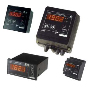
In laboratories, recording potentiometers are often used as recording instruments. The main advantage of which is the ability to simultaneously connect several thermocouples. But data registration in them is made in the form of graphs on a paper tape. And in my opinion, it is simply not rational to carry out automatic measurements in order to manually process the data later. And that is exactly what happened in the laboratories of the university where I studied. And then one day, I was on the 5th year, I was offered to deal with this problem. In the case of a successful solution, the department received a complex for automating temperature measurements, and I got an engineering degree.
A few years earlier, for the purpose of automating measurements, the department bought an AD1P (analog-digital conversion) La1.5 PCI card manufactured by Rudnev-Shilyaev.
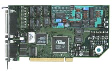
But the software that came with the board was terribly inconvenient, and it was only good enough to test the board’s performance. It was possible to see the maximum, that the board issues some data, but it was almost impossible to measure anything. Since I studied at the department of boiler and reactor structures, the experts here were in energy, steam boilers and nuclear reactors, but few people understood computers and ADC boards here. So this board was abandoned on the shelf, where it was gathering dust, waiting for its time. In general, I started developing a good and convenient program for our needs. And I want to share with you what difficulties I had and what finally happened.
CJSC Rudnev-Shilyaev apparently understood that their software that comes with the board is simply not possible to use, so they provided a pretty good SDK for many programming languages. I decided not to be wise, and since I needed a guaranteed result for a very specific time, I decided to write on what I had the experience of writing something more complicated than the “Hellow world” - namely on Delphi. Especially since I had to develop a program for Windows. There was no Linux in the university, and the firewood to the board was under a very old kernel branch and it did not work at home under Linux, and there was neither time nor experience to finish the kernel modules. The SDK was quite convenient, but there were several specific points that were not explicitly indicated and problems arose.
')
The board worked as follows: the sampling frequency, signal gain, the channel numbers for digitization were set (there were 32 analog inputs on the board) and the buffer size was set (in the computer’s memory, there was no memory on the board) the board stopped digitizing and waited for permission to overwrite the buffer. I naively believed that the board buffer records the value of the signal in volts applied to the input. But it turned out that it records the ADC code, which still needs to be recalculated into volts, taking into account the input range and digit capacity of the ADC board. Maybe this is the standard for such devices, but it was not explicitly stated anywhere in the documentation for the board! The second pitfall was the fact that the board returns the ADC code in 16 bit format. This, too, was not explicitly stated anywhere.
When these features were taken into account and my program started working, another very significant problem emerged that could have simply made all my work in vain. The board was too sensitive. Even my simple movement around the room created strong electromagnetic interference and distorted the measurement results. There was no question of any measurements on the stands with the blow fans and frequency converters turned on. It was necessary to invent something.
Through trial and error, I noticed the following: if you digitize only one channel, then there is significant noise in the measurements only at the beginning of the measurement and very little noise in the process. If we measure on several channels, the board switches from channel to channel every time and adds a lot of noise. That's why I decided to change the algorithm of work and make switching between channels programmatically and not in hardware. That is, in the past, with multi-channel measurement, the board gave alternating values to the buffer from the channels 1 2 3 1 2 3 1 2 3 and now I programmatically forced it to output this 1 1 1 2 2 2 3 3 3. Then I found the arithmetic average of the channel, thereby trimming all random values. The fee works at a frequency of up to 500 kHz. On the coefficient of the student at 500 thousand measurements per second can not speak. All noises are discarded and the accuracy of the measurement completely rests on the accuracy of the ADC of the board itself.
I called the program Etaker. Here are some screenshots.


With the help of the Etaker program, data were obtained in the course of diploma works by other students of our department, in particular, studies of the thermophysical properties of protective oxide film films, combustion of granulated fuel in a fluidized bed, and a number of measurements were made at an experimental unit for the continuous coking of coal.

Here are the sources , a detailed description of the program is in the user's manual and the installer of the program itself.
Thus, the department of KiRS AltGTU received a modern software and hardware complex for multichannel automatic temperature measurements, and I am excellent and an engineering degree. What unspeakably happy!
Source: https://habr.com/ru/post/95037/
All Articles