Independent study of circuit design. Basic concepts. Part 1
The study of digital circuitry must begin with automata theory. In this article, you can find some basic things that will help not to get lost in future articles. I tried to make the article easy to read and I am sure that an unprepared reader will be able to easily understand it.
A signal is a tangible storage medium used to transmit messages over a communication system. A signal, unlike a message, can be generated, but its reception is not mandatory (the message must be received by the receiving party, otherwise it is not a message, but only a signal).
The article deals with a digital discrete signal. This is a signal that has several levels. Obviously, a binary signal has two levels - and they are taken as 0 and 1. When a high level is indicated by one, and a low level is zero, this logic is called positive, otherwise negative.
')
A digital signal can be represented as a timing diagram.

In nature, discrete signals do not exist; therefore, they are replaced by analog ones. An analog signal can not go from 0 to 1 instantly, so this signal has a front and a cut .
If you draw in a simplistic way, it looks like this:
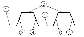
1 - low signal level, 2 - high signal level, 3 - signal increase (front), 4 - signal drop (slice)
Signals can be converted. For this purpose, logical elements are used in practice, and logical functions are formally used to record this. Here are the main ones:
Negation - inverts the signal.
In the diagrams is indicated as:
Logical OR (logical addition, disjunction)
In the diagram:
Logical AND (logical multiplication, conjunction)
In the diagram:
The last two may have a negative output (AND-NO, OR-NO). The values of their logical functions are inverted, and on the circuit the output is drawn in a circle.
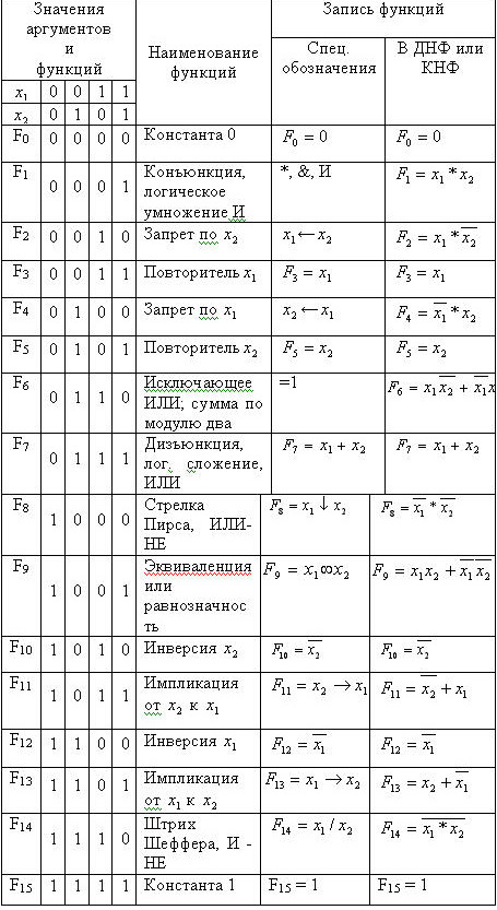
The pivot table of the logical functions of the two arguments is as follows:
Working with logical functions is based on the laws of algebra of logic , the foundations of which are set out in the attached file. There are also tasks for self-control and control questions on the topic.
A logical circuit is a set of logical electronic elements interconnected in such a way that the given law of the functioning of the circuit is fulfilled, in other words, a given logical function is fulfilled.
According to the dependence of the output signal on the input, all electronic logic circuits can be divided into:
Schemes of the first kind , i.e. combinational circuits whose output signal depends only on the state of the input signals at each time point;
Circuits of the second kind or accumulative circuits ( sequential circuits) containing accumulative circuits ( memory elements ), the output of which depends on both the input signals and the state of the circuit at previous points in time.
According to the number of inputs and outputs, the circuits are: with one input and one output, with several inputs and one output, with one input and several outputs, with several inputs and outputs.
According to the method of synchronization, the circuits come with external synchronization (synchronous automata), with internal synchronization (asynchronous automata are their particular case).
Almost any computer consists of a combination of schemes of the first and second kind of different complexity. Thus, the basis of any digital automaton processing digital information is electronic elements of two types: logical or combination and storage . Logic elements perform the simplest logical operations on digital information, while the storage elements serve to store it. As you know, the logical operation consists in converting the input digital information to the output according to certain rules.
We can assume that the elementary logical functions are the logical operators of the electronic elements mentioned, i.e. schemes. Each such scheme is indicated by a specific graphic symbol. (They were presented above - Elements AND, OR, NOT, OR-NOT, AND-NOT)
As an example, the following is an electrical functional logic converter (combinational machine) circuit that implements a logic function in the elemental basis of logical elements AND, OR, NOT.

To consolidate, I suggest that you independently synthesize a logic circuit that implements the following logical functions:

You can do this for example in Electronic workbench.
Here, for example, the first task performed:

And the ewb 5.12 file .
Hint: In order to include the legend in accordance with the national GOST, the line DIN = ON must be added to the EWB.INI configuration file
This concludes the first part of the article. Hope she was not too tiring. All of the above is necessary to understand the principles of working with signals in electrical circuits. The next article will discuss ways to minimize logical functions, the concept of an abstract automaton, and an example of RS-flip-flop synthesis.
A signal is a tangible storage medium used to transmit messages over a communication system. A signal, unlike a message, can be generated, but its reception is not mandatory (the message must be received by the receiving party, otherwise it is not a message, but only a signal).
The article deals with a digital discrete signal. This is a signal that has several levels. Obviously, a binary signal has two levels - and they are taken as 0 and 1. When a high level is indicated by one, and a low level is zero, this logic is called positive, otherwise negative.
')
A digital signal can be represented as a timing diagram.
In nature, discrete signals do not exist; therefore, they are replaced by analog ones. An analog signal can not go from 0 to 1 instantly, so this signal has a front and a cut .
If you draw in a simplistic way, it looks like this:
1 - low signal level, 2 - high signal level, 3 - signal increase (front), 4 - signal drop (slice)
Signals can be converted. For this purpose, logical elements are used in practice, and logical functions are formally used to record this. Here are the main ones:
Negation - inverts the signal.
In the diagrams is indicated as:
Logical OR (logical addition, disjunction)
In the diagram:
Logical AND (logical multiplication, conjunction)
In the diagram:
The last two may have a negative output (AND-NO, OR-NO). The values of their logical functions are inverted, and on the circuit the output is drawn in a circle.
The pivot table of the logical functions of the two arguments is as follows:
Working with logical functions is based on the laws of algebra of logic , the foundations of which are set out in the attached file. There are also tasks for self-control and control questions on the topic.
Designing Logic Circuits Using Logic Algebra Functions
A logical circuit is a set of logical electronic elements interconnected in such a way that the given law of the functioning of the circuit is fulfilled, in other words, a given logical function is fulfilled.
According to the dependence of the output signal on the input, all electronic logic circuits can be divided into:
Schemes of the first kind , i.e. combinational circuits whose output signal depends only on the state of the input signals at each time point;
Circuits of the second kind or accumulative circuits ( sequential circuits) containing accumulative circuits ( memory elements ), the output of which depends on both the input signals and the state of the circuit at previous points in time.
According to the number of inputs and outputs, the circuits are: with one input and one output, with several inputs and one output, with one input and several outputs, with several inputs and outputs.
According to the method of synchronization, the circuits come with external synchronization (synchronous automata), with internal synchronization (asynchronous automata are their particular case).
Almost any computer consists of a combination of schemes of the first and second kind of different complexity. Thus, the basis of any digital automaton processing digital information is electronic elements of two types: logical or combination and storage . Logic elements perform the simplest logical operations on digital information, while the storage elements serve to store it. As you know, the logical operation consists in converting the input digital information to the output according to certain rules.
We can assume that the elementary logical functions are the logical operators of the electronic elements mentioned, i.e. schemes. Each such scheme is indicated by a specific graphic symbol. (They were presented above - Elements AND, OR, NOT, OR-NOT, AND-NOT)
As an example, the following is an electrical functional logic converter (combinational machine) circuit that implements a logic function
in the elemental basis of logical elements AND, OR, NOT.To consolidate, I suggest that you independently synthesize a logic circuit that implements the following logical functions:
You can do this for example in Electronic workbench.
Here, for example, the first task performed:
And the ewb 5.12 file .
Hint: In order to include the legend in accordance with the national GOST, the line DIN = ON must be added to the EWB.INI configuration file
This concludes the first part of the article. Hope she was not too tiring. All of the above is necessary to understand the principles of working with signals in electrical circuits. The next article will discuss ways to minimize logical functions, the concept of an abstract automaton, and an example of RS-flip-flop synthesis.
Source: https://habr.com/ru/post/91922/
All Articles