Non-standard cooling of D-Link routers on the example of DSL-2640U model
Surely many of you have seen articles related to the cooling of routers of various models. In this article I wanted to talk about the not quite standard approach to this problem. The unusual thing is that the cooler is located not on top of my case, but on the bottom. Bad cooling will turn out tell you - at all. In this mode, the router has been working perfectly for several months without a glitch. I was forced to make cooling one not very pleasant case, when the modem, after working for several days non-stop, made a spontaneous reset of all settings.
So, let's begin. We will need:
UPD: added 2 chip radiators, replacement of electrolytic capacitors.
')
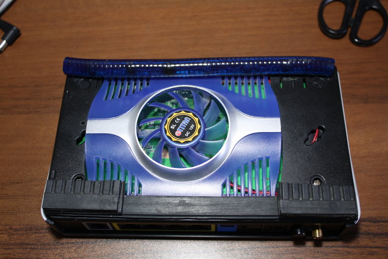
To do this, we will analyze the router and in the lower part of the case we will make a hole according to the size of the acquired cooler (I think it is better in this case to purchase with one fan). We cut it out with either a jigsaw, or a Dremel, or, in extreme cases, we cut it out with a knife, but here we must be careful: for the first time do not press hard, the knife can easily come off and then it will be more difficult to align the cut line. We get something like this:
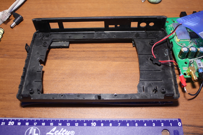
Next, fasten the cooler in our hole, either with screws or with glue. I consider the first option more preferable, since it will be easier to dismantle the cooler in the future if the need arises. Holes drilled Dremel or conventional drill or screwdriver. Here you should take a drill about 0.5 mm thinner than you will use screws to have something to cling to. We install the cooler and seal its edges with tape so that the board does not close the screw heads.


The first stage is over.
You can do this at will, but by myself I can say that the noise at 12 volts is significant. The voltage was chosen experimentally: first 9V, then 7V, and eventually lowered to 4.5V.
The connection of the resistor is very simple:

Since in this circuit we are only interested in current, resistance and voltage, we can take the electric motor (M1) as resistance. It remains only to correctly calculate the resistance R1. This will help us Ohm's law.
To begin with, let's calculate the resistance of the cooler itself: R = U / I (look at the current strength on the case, in my case it was 0.17A) R = 12 / 0.17 = 70.59 oM.
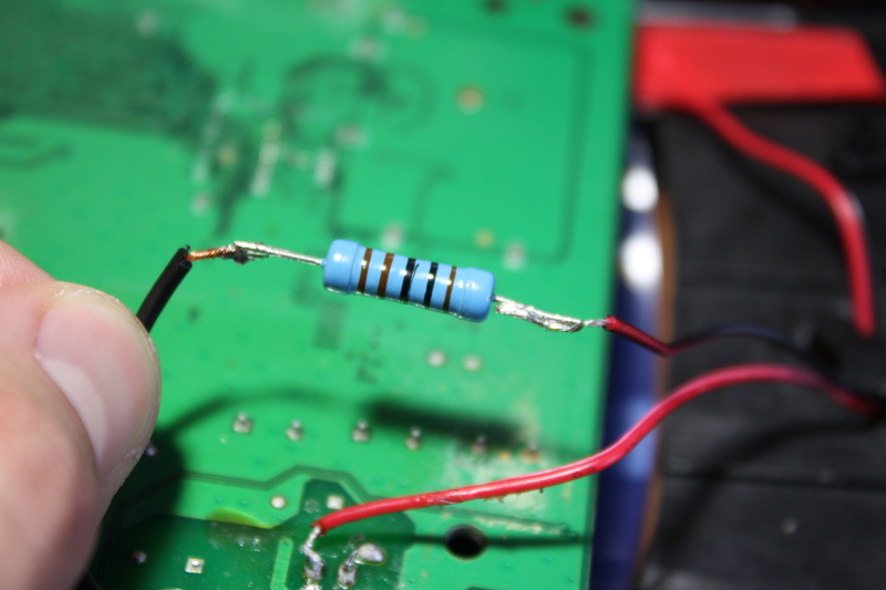
Do not forget to calculate the power of the resistor, if you take a smaller power, it can quickly burn out. P = U * I = 7.5 * 0.17 = 1.125W. We go to the store, buy a resistor 110-120 Ohm 1.5W and solder in series with the cooler.
Then we solder the wires to the board: one is soldered directly to the socket of the power supply socket, the other is soldered to the power switch (after having checked which of the 6 contacts is on-off, and then soldered the first time to the other, and the cooler continued to rotate even when the power was off) . We are not afraid to check the polarity with the conclusions of the cooler; if it is connected incorrectly, it simply will not rotate.

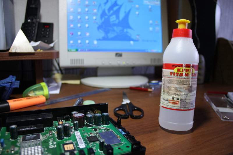
Next, install the board in its place and fix the resistor with glue (I used Titan construction glue). No special hot melts will be needed, since the current passing through the resistor is considerably small (after the assembly of the structure, the device showed ≈55m).

On the advice of readers, he added radiators for 2 Broadcom chips. The size of the chips was measured with a caliper (dimensions 19 * 11 and 12 * 12mm). They were cut with a hacksaw from an old computer. After sawing, finishing was done first with a needle file and coarse sandpaper, then fine and planted on AlSil-3 thermal paste:
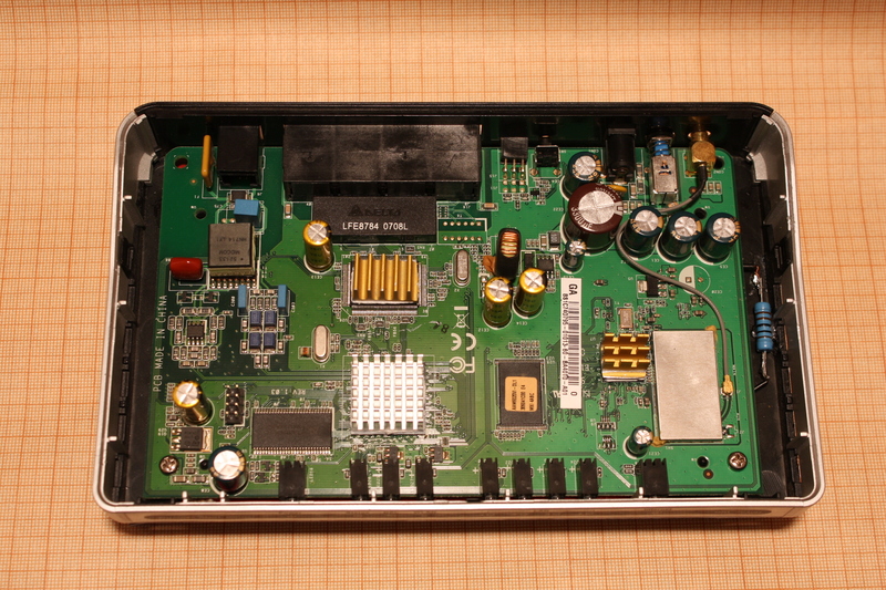
In the process of upgrading, inflated capacitors were detected (usually covering one voltage all at once). It was decided to replace with new ones. But I ran into such a problem: the solder on the board does not melt either 25 or 40W with a soldering iron, or even softened. The solution was found: take a little solder on the sting, warm up the contacts and calmly dismantle the old elements. We make installation of fresh capacitors. Do not hesitate to buy capacitors with a slightly higher operating voltage than they are on the board (talking about the voltage of capacitors with a man working in a LG and Samsung repair center, he said that it is even better to supply them with a large operating voltage).
On this with the inside finished.
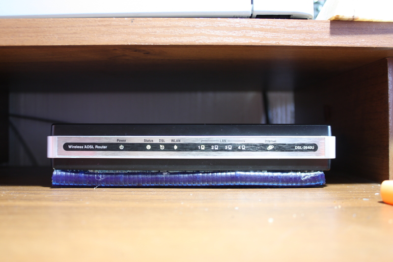
Now, so that the cooler does not suffocate, you need to raise the modem over the table. Any available material will do for this: here, how much fantasy is enough. I have implemented this:
Behind used pieces of rubber in several layers, in front - a piece of duralight (if desired, you can connect to the network). In the working position it looks like this:
It is not necessary to drill any holes for air exhaust, it goes perfectly through the holes on top of the device and from other slots. The noise level in this mode of operation is minimal: the work of the cooler is audible only if you turn off all noise sources in the apartment (it is even interrupted by the sound of the TV working behind the wall). As for cooling efficiency, it was at a high level: the modem stopped overheating and is no longer reset, heating is present, but very low (with 2 constantly connected computers: one with wire, the other through wifi, torrents are distributed almost always from both machines).
So, let's begin. We will need:
- directly router
- cooler for hdd 3.5
- 4-6 screws or small screws for fixing the cooler
- jigsaw knife or dremel
- soldering iron, flux, solder
- glue
- and one more thing, which will be discussed later
UPD: added 2 chip radiators, replacement of electrolytic capacitors.
')
Let's start preparing
To do this, we will analyze the router and in the lower part of the case we will make a hole according to the size of the acquired cooler (I think it is better in this case to purchase with one fan). We cut it out with either a jigsaw, or a Dremel, or, in extreme cases, we cut it out with a knife, but here we must be careful: for the first time do not press hard, the knife can easily come off and then it will be more difficult to align the cut line. We get something like this:
Next, fasten the cooler in our hole, either with screws or with glue. I consider the first option more preferable, since it will be easier to dismantle the cooler in the future if the need arises. Holes drilled Dremel or conventional drill or screwdriver. Here you should take a drill about 0.5 mm thinner than you will use screws to have something to cling to. We install the cooler and seal its edges with tape so that the board does not close the screw heads.
The first stage is over.
Reduced fan speed
You can do this at will, but by myself I can say that the noise at 12 volts is significant. The voltage was chosen experimentally: first 9V, then 7V, and eventually lowered to 4.5V.
The connection of the resistor is very simple:
Since in this circuit we are only interested in current, resistance and voltage, we can take the electric motor (M1) as resistance. It remains only to correctly calculate the resistance R1. This will help us Ohm's law.
To begin with, let's calculate the resistance of the cooler itself: R = U / I (look at the current strength on the case, in my case it was 0.17A) R = 12 / 0.17 = 70.59 oM.
- From a school physics course, we know that with series connection of conductors, the current in all series-connected conductors is the same: I = I (resistor) = I (cooler) .
- The voltage (or potential difference) at the ends of the section is equal to the sum of the voltages on the individual conductors: U = U (resistor) + U (cooler) . It follows that the voltage across the resistor should be 7.5V.
- Following Ohm's law, the voltage of individual conductors will be equal to U (resistor) = I / R (resistor) and U (cooler) = I / R (cooler) . This implies: U (p) / U (k) = R (p) / R (k) . Substituting the numbers in our formula and we get the resistance 117.65Ω
Do not forget to calculate the power of the resistor, if you take a smaller power, it can quickly burn out. P = U * I = 7.5 * 0.17 = 1.125W. We go to the store, buy a resistor 110-120 Ohm 1.5W and solder in series with the cooler.
Then we solder the wires to the board: one is soldered directly to the socket of the power supply socket, the other is soldered to the power switch (after having checked which of the 6 contacts is on-off, and then soldered the first time to the other, and the cooler continued to rotate even when the power was off) . We are not afraid to check the polarity with the conclusions of the cooler; if it is connected incorrectly, it simply will not rotate.
Next, install the board in its place and fix the resistor with glue (I used Titan construction glue). No special hot melts will be needed, since the current passing through the resistor is considerably small (after the assembly of the structure, the device showed ≈55m).
More radiators?
On the advice of readers, he added radiators for 2 Broadcom chips. The size of the chips was measured with a caliper (dimensions 19 * 11 and 12 * 12mm). They were cut with a hacksaw from an old computer. After sawing, finishing was done first with a needle file and coarse sandpaper, then fine and planted on AlSil-3 thermal paste:
Inflated capacitors - need to be changed
In the process of upgrading, inflated capacitors were detected (usually covering one voltage all at once). It was decided to replace with new ones. But I ran into such a problem: the solder on the board does not melt either 25 or 40W with a soldering iron, or even softened. The solution was found: take a little solder on the sting, warm up the contacts and calmly dismantle the old elements. We make installation of fresh capacitors. Do not hesitate to buy capacitors with a slightly higher operating voltage than they are on the board (talking about the voltage of capacitors with a man working in a LG and Samsung repair center, he said that it is even better to supply them with a large operating voltage).
On this with the inside finished.
Turbocharger bottom
Now, so that the cooler does not suffocate, you need to raise the modem over the table. Any available material will do for this: here, how much fantasy is enough. I have implemented this:
Behind used pieces of rubber in several layers, in front - a piece of duralight (if desired, you can connect to the network). In the working position it looks like this:
It is not necessary to drill any holes for air exhaust, it goes perfectly through the holes on top of the device and from other slots. The noise level in this mode of operation is minimal: the work of the cooler is audible only if you turn off all noise sources in the apartment (it is even interrupted by the sound of the TV working behind the wall). As for cooling efficiency, it was at a high level: the modem stopped overheating and is no longer reset, heating is present, but very low (with 2 constantly connected computers: one with wire, the other through wifi, torrents are distributed almost always from both machines).
Source: https://habr.com/ru/post/91842/
All Articles