Java 2D and depth buffer
 Hello. I want to share with you my "bicycle", if someone else it is useful.
(An article on how to implement a depth buffer in Graphics2D).
')
Problem
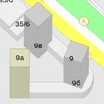
Once it took to draw a map of the city with 3D buildings. In this case, it was possible to use only standard Swing `s Graphics2D. With the projection of polygons on the 2D plane, everything is clear and trivial, but for high-grade 3D this is not enough, since buildings are complex and they can overlap each other. As a result, the order of drawing the edges of the building becomes important (the front face must be drawn after the back). It would seem that you can sort all the faces in the right order and everything will be perfect. However, if the faces intersect, sorting does not solve the problem. Example in the picture:
As far as I know, this problem has at least two solutions: one of them is the use of a depth buffer (z-buffer), the other is splitting polygons into small parts in order to eliminate intersections.
Decision
The standard implementation of the depth buffer (as far as I know) is not in Java 2D and for a very long time I could not find a solution to this problem until I looked closely at java.awt.Composite. As it turned out, it is almost perfect for implementing the depth buffer and this is how it can be done ( project page with associates ).
As you well know, the depth buffer is nothing more than an array of z-coordinates of the screen pixels. Before starting the drawing procedure, it is reset to some value (for example, the value of the furthest z-coordinate is set). Then, when each new point is displayed on the screen, it is checked whether the z-coordinate value of the output point is smaller than the z-coordinate value of the depth already stored in the buffer. And if so, the point will be displayed on the screen and the z-coordinate value in the buffer will be updated, otherwise the point will be simply discarded. Thus, the correct picture will be displayed on the screen.
The basic idea is that we can use the Composite (composite) to implement the depth buffer, since during the drawing process each point displayed on the screen is processed by the composite installed in the graphic context. Thus, in a composite, we can create an array of coordinates (the size of which coincides with the size of the graphic context) and check each output point in our composite. As you can see, it sounds easy.
Implementation
To implement the above, we first need to learn how to determine the value of the z-coordinate for an arbitrary point of the screen (x, y). To do this, we add the corresponding ZValueResolver interface:
/**
* Converts given x, y coordinate to z coordinate
* @author caiiiycuk
*
*/
public interface ZValueResolver {

/**
* @param x given x coordinate
* @param y given y coordinate
* @return z coordinate of x, y
*/
double resolve( double x, double y);

...
}
Before calling any drawing method accessible through Graphics2D (for example, drawPolygon), we will describe the corresponding ZValueResolver, which can get the z-coordinate for any point (x, y) of this polygon. (Looking ahead, I will say that in most cases the implementation is trivial, since almost always the ZValueResolver is described by a three-point plane equation, there is even a corresponding standard implementation ).
Further, everything is simple: let's implement the java.awt.Composite interface, which will store the values of the depth buffer:
/**
* ZComposite emulates ZBuffer
* @author caiiiycuk
*/
public class ZComposite implements Composite {

...

protected double [] buffer;
protected int width;
protected int height;

...

/**
* Set z-value in buffer for given point
* @param x coordinate
* @param y coordinate
* @param value z-value
*/
public void setZOf( int x, int y, double value ) {
if (x >= width || x < 0 ||
y >= height || y < 0) {
throw new IllegalArgumentException( "Point [" + x + ", " + y + "] is outside of the Z Buffer array" );
}

buffer[y*width + x] = value ;
}

public double getZOf( int realX, int realY) {
return buffer[realY*width + realX];
}

...

}
Thus, we have a depth buffer, we can determine the z coordinate of any point (x, y), it remains to implement only the CompositeContext :
/**
* Composite emulates Z buffer
* @author caiiiycuk
*/
public class ZCompositeContext implements CompositeContext {

protected final static byte R_BAND = 0;
protected final static byte G_BAND = 1;
protected final static byte B_BAND = 2;

protected ZComposite zComposite;

ZCompositeContext(ZComposite zComposite) {
this .zComposite = zComposite;
}

/**
* {@inheritDoc}
*/
public void compose(Raster src, Raster dstIn, WritableRaster dstOut) {
ZValueResolver zValueResolver = zComposite.getValueResolver();

if (zValueResolver == null ) {
throw new IllegalArgumentException( "You must set a ZValueResolver before draw any polygon with this composite" );
}

int maxX = dstOut.getMinX() + dstOut.getWidth();
int maxY = dstOut.getMinY() + dstOut.getHeight();

for ( int y = dstOut.getMinY(); y < maxY; y++) {
for ( int x = dstOut.getMinX(); x < maxX; x++) {
int dstInX = -dstIn.getSampleModelTranslateX() + x;
int dstInY = -dstIn.getSampleModelTranslateY() + y;

double dstZ = zComposite.getZOf(dstInX, dstInY);
double srcZ = zValueResolver.resolve(dstInX, dstInY);

if (srcZ < dstZ) {
zComposite.setZOf(dstInX, dstInY, srcZ);
dstOut.setSample(x, y, R_BAND, src.getSample(x, y, R_BAND)); //R
dstOut.setSample(x, y, G_BAND, src.getSample(x, y, G_BAND)); //G
dstOut.setSample(x, y, B_BAND, src.getSample(x, y, B_BAND)); //B
} else if (srcZ == dstZ) {
dstOut.setSample(x, y, R_BAND, src.getSample(x, y, R_BAND)); //R
dstOut.setSample(x, y, G_BAND, src.getSample(x, y, G_BAND)); //G
dstOut.setSample(x, y, B_BAND, src.getSample(x, y, B_BAND)); //B
} else {
dstOut.setSample(x, y, R_BAND, dstIn.getSample(x, y, R_BAND)); //R
dstOut.setSample(x, y, G_BAND, dstIn.getSample(x, y, G_BAND)); //G
dstOut.setSample(x, y, B_BAND, dstIn.getSample(x, y, B_BAND)); //B
}
}
}
}

/**
* {@inheritDoc}
*/
public void dispose() {
}

}
Thus, we write the incoming pixel only if it matches us in the z-coordinate (srcZ <= dstZ).
Anti-Aliasing
Surprisingly, this implementation works only while we are not trying to use Anti-Aliasing. Enabling smoothing leads to unpredictable effects and artifacts. This is connected with the implementations of the smoothing algorithm itself. The essence of the problem is that the algorithm when drawing periodically goes beyond the "frame" of the drawn polygons, which leads to an incorrect definition of z-coordinates. In this regard, we had to add a checkout of the output currents to the ground in the implementation of ZValueResolver, which negatively affected the performance, but allowed the depth buffer to be correctly implemented in the smoothing mode.
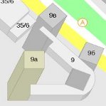
Here's what happened as a result (hooray! Goal achieved):
Just a simple example of working with my implementation of the depth buffer (well, you never know).
Thanks for attention.
Source: https://habr.com/ru/post/91247/
All Articles