Hand made - Anemometer (wind speed meter)
A task appeared to collect an anemometer for one project in order to capture data on a computer via USB interface. The article will discuss more about the anemometer itself than about the data processing system from it:

')
So, for the manufacture of the product needed the following components:
Three pieces of copper wire 1 cm long each at an angle of 120 degrees were soldered to the brass barrel. In the hole of the barrel, I soldered a rack from a Chinese player with a thread on the end.
The candy tube was cut into 3 pieces about 2 cm long.
I cut 2 balls in half and with the help of small screws from the same player and polystyrene glue (glue gun) I attached the halves of the ball to the tubes from the lollipop.
Tubes with ball halves put on the soldered pieces of wire, all secured with glue on top.
The anemometer bearing element is a metal rod from a ballpoint pen. In the lower part of the rod (where the cork was inserted) I inserted the disk from the mouse (encoder). In the design of the mouse itself, the lower part of the encoder rested against the body of the mouse, forming a point bearing, there was lubrication, so the encoder spun easily. But it was necessary to fix the upper part of the rod, for this I picked up a suitable piece of plastic with a hole exactly along the diameter of the rod (such a piece was cut from the carriage extension system CD-ROMa). It remained to solve the problem so that the rod with the encoder did not fall out of the point bearing, so on the rod directly in front of the retaining element I soldered a few drops of solder. Thus, the rod spun freely in the holding structure, but did not fall out of the bearing.
The reason why the scheme with the encoder was chosen is the following: all articles on home-made anemometers on the Internet described their production on the basis of a DC motor from a player, CD-ROM or any other product. The problem with such devices is firstly in their calibration and low accuracy at low wind speed, and secondly in the nonlinear characteristic of wind speed with respect to the output voltage, i.e. There are certain problems for transferring information to a computer; When using an encoder, there is no such problem, since the dependence is linear. The accuracy is highest, since the encoder gives about 50 pulses per revolution of the axis of the anemometer, but the converter circuit, which contains a microcontroller that counts the number of pulses per second on one of the ports and outputs this value to the USB port, is somewhat complicated.
Laboratory anemometer was used for calibration.
The whole process is clearly visible on the rollers:
Thanks for attention
ZY on the first video, something incomprehensible with sound, the hair dryer there was very noisy, which YouTube converted it like that - I don’t know if that is not a technosound :)
')
1. Components
So, for the manufacture of the product needed the following components:
- Ball mouse Mitsumi - 1 pc.
- Ping-pong ball - 2 pcs.
- A piece of plexiglass of suitable size
- Copper wire section 2.5 mm2 - 3 cm
- Ballpoint pen core - 1 pc.
- Chupa Chups Candy Stick - 1 pc.
- Cable clip - 1 pc.
- Hollow brass barrel 1 pc.
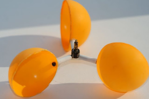
2. Manufacturing impeller
Three pieces of copper wire 1 cm long each at an angle of 120 degrees were soldered to the brass barrel. In the hole of the barrel, I soldered a rack from a Chinese player with a thread on the end.
The candy tube was cut into 3 pieces about 2 cm long.
I cut 2 balls in half and with the help of small screws from the same player and polystyrene glue (glue gun) I attached the halves of the ball to the tubes from the lollipop.
Tubes with ball halves put on the soldered pieces of wire, all secured with glue on top.
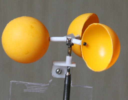
3. Manufacturing the main part
The anemometer bearing element is a metal rod from a ballpoint pen. In the lower part of the rod (where the cork was inserted) I inserted the disk from the mouse (encoder). In the design of the mouse itself, the lower part of the encoder rested against the body of the mouse, forming a point bearing, there was lubrication, so the encoder spun easily. But it was necessary to fix the upper part of the rod, for this I picked up a suitable piece of plastic with a hole exactly along the diameter of the rod (such a piece was cut from the carriage extension system CD-ROMa). It remained to solve the problem so that the rod with the encoder did not fall out of the point bearing, so on the rod directly in front of the retaining element I soldered a few drops of solder. Thus, the rod spun freely in the holding structure, but did not fall out of the bearing.
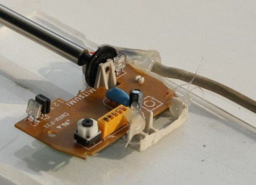
The reason why the scheme with the encoder was chosen is the following: all articles on home-made anemometers on the Internet described their production on the basis of a DC motor from a player, CD-ROM or any other product. The problem with such devices is firstly in their calibration and low accuracy at low wind speed, and secondly in the nonlinear characteristic of wind speed with respect to the output voltage, i.e. There are certain problems for transferring information to a computer; When using an encoder, there is no such problem, since the dependence is linear. The accuracy is highest, since the encoder gives about 50 pulses per revolution of the axis of the anemometer, but the converter circuit, which contains a microcontroller that counts the number of pulses per second on one of the ports and outputs this value to the USB port, is somewhat complicated.
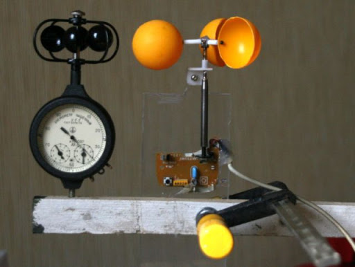
4. Testing and calibration
Laboratory anemometer was used for calibration.
The whole process is clearly visible on the rollers:
Thanks for attention
ZY on the first video, something incomprehensible with sound, the hair dryer there was very noisy, which YouTube converted it like that - I don’t know if that is not a technosound :)
Source: https://habr.com/ru/post/90044/
All Articles