Features and DHCP settings on Cisco routers (Part 2)
This article is a continuation of the previous article on the basic DHCP configuration on a Cisco router. In this article I want to consider the configuration and configuration of a centralized DHCP server and DHCP Relay agents.
As an example, take the following scheme:

On router R3 there is a DHCP server that centrally issues addresses on the LAN_1 and LAN_2 networks . Routers R1 and R2 in this scheme are DHCP-Relay agents
Configure two address pools on R3 for each local network:
')
Naturally, if necessary, you can add additional options to the pool.
The next step is to configure the DHCP-Relay agents on R1 and R2 routers. The essence of the DHCP Relay is to forward the broadcast packet from the client with the unaddressed packet to the DHCP server.
The configuration of the agents is done with the following command:
R2 router is configured in the same way
It should be noted that the ip helper-address xxxx command forces to forward broadcast UDP messages not only of the DHCP protocol, the following requests will also be sent by default:
If we want to rectify the situation, in the global configuration mode we determine which requests to forward and which not -:
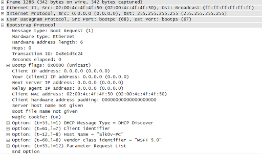
Client sends standard DISCOVERY:
which is sent by the Relay Agent towards the DHCP server (modified fields are marked in red):
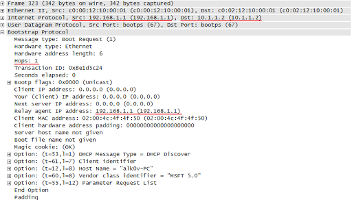
As you can see from the picture, the message is now forwarded with a unicast packet with source 192.168.1.1 (interface of the router to which the broadcast packet was received) and recipient 10.1.1.2 (the address specified by the ip helper-address command. In addition, the address 192.168.1.1 is specified in the field Relay agent IP address
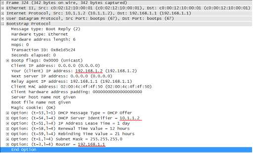
Based on the source address of the message, the DHCP server determines from which pool to output addresses. For R2, the request goes with the source address 192.168.2.1 and the server issues the address from the LAN_2 pool.
The OFFER clause from R3 to R1 is as follows:
R1 sends it to the client by changing only the source address to 192.168.1.1 and the recipient to 192.168.1.2 ( link to the screenshot )
This is how messaging between client, agent and server looks like:

For this example to work correctly, it is important to consider the following point: router R3 receives packets from R1 with source address 192.168.1.1, so on R3 network 192.168.1.0 must be in the routing table, I configured EIGRP between routers to solve this problem. See the table:
Thank you for your attention, discussion is welcome.
1. Configuration
As an example, take the following scheme:
On router R3 there is a DHCP server that centrally issues addresses on the LAN_1 and LAN_2 networks . Routers R1 and R2 in this scheme are DHCP-Relay agents
Configure two address pools on R3 for each local network:
')
! , ( R1 R2
ip dhcp excluded-address 192.168.1.1
ip dhcp excluded-address 192.168.2.1
! LAN_1
ip dhcp pool LAN1
network 192.168.1.0 255.255.255.0
ip default-router 192.168.1.1
! LAN_2
ip dhcp pool LAN2
network 192.168.2.0 255.255.255.0
ip default-router 192.168.2.1
Naturally, if necessary, you can add additional options to the pool.
The next step is to configure the DHCP-Relay agents on R1 and R2 routers. The essence of the DHCP Relay is to forward the broadcast packet from the client with the unaddressed packet to the DHCP server.
The configuration of the agents is done with the following command:
! , , f0/0 ,
interface fa0/0
ip helper-address 10.1.1.2
R2 router is configured in the same way
interface fa0/0
ip helper-address 10.1.2.2
It should be noted that the ip helper-address xxxx command forces to forward broadcast UDP messages not only of the DHCP protocol, the following requests will also be sent by default:
- Time (udp 37)
- TACACS (udp 49)
- DNS (udp 53)
- TFTP (udp 69)
- NetBIOS name service (udp 137)
- NetBIOS datagram service (udp 138)
If we want to rectify the situation, in the global configuration mode we determine which requests to forward and which not -:
no ip forward-protocol udp 37
no ip forward-protocol udp 53
2. How does it work?
Client sends standard DISCOVERY:
which is sent by the Relay Agent towards the DHCP server (modified fields are marked in red):
As you can see from the picture, the message is now forwarded with a unicast packet with source 192.168.1.1 (interface of the router to which the broadcast packet was received) and recipient 10.1.1.2 (the address specified by the ip helper-address command. In addition, the address 192.168.1.1 is specified in the field Relay agent IP address
Based on the source address of the message, the DHCP server determines from which pool to output addresses. For R2, the request goes with the source address 192.168.2.1 and the server issues the address from the LAN_2 pool.
The OFFER clause from R3 to R1 is as follows:
R1 sends it to the client by changing only the source address to 192.168.1.1 and the recipient to 192.168.1.2 ( link to the screenshot )
This is how messaging between client, agent and server looks like:
3. Conclusion
For this example to work correctly, it is important to consider the following point: router R3 receives packets from R1 with source address 192.168.1.1, so on R3 network 192.168.1.0 must be in the routing table, I configured EIGRP between routers to solve this problem. See the table:
R3#sh ip ro

Gateway of last resort is not set

10.0.0.0/24 is subnetted, 2 subnets
C 10.1.2.0 is directly connected, FastEthernet0/0
C 10.1.1.0 is directly connected, FastEthernet0/1
D 192.168.1.0/24 [90/307200] via 10.1.1.1, 00:00:16, FastEthernet0/1
D 192.168.2.0/24 [90/307200] via 10.1.2.1, 00:02:17, FastEthernet0/0
Thank you for your attention, discussion is welcome.
Source: https://habr.com/ru/post/89997/
All Articles