Comparison Arduino boards - Mars Rover
Humanity is developing in a strange way. Technical progress has so rapidly changed a person’s life that we somehow don’t imagine another life without cell phones, computers, laptops, digital photo frames and cameras. It seems all this has always been. And who comes up with all this and does? Do these engineers have a super brain? And you know what? You yourself can try to do something electronic and amazing. The “product” you have created may not be sold in millions of copies, but you will actually be able to surprise your friends. If you are at least a little in the soul of a radio amateur, and you are not afraid of the word soldering iron, and you have a little perseverance, you will succeed.
Where to begin? Perhaps there are two interesting possibilities - this is the Arduino board or the Mars Rover board. I'll try to explain what it is.
')
First of all, both boards were originally designed for electronic modeling - the creation of all kinds of electronic toys, robots, typewriters and other prikolyushek. This is a kind of "electronic designers". With their help, you can learn the basics of circuit design and electronics and programming, or you can create real, useful home automation devices. Interestingly, the schemes of these designer boards are freely available, published by manufacturers on the Internet. There are also a lot of examples of implemented "devices" for Arduino on the Internet.
The rover motherboard is not yet so well known, but its authors themselves make machine-robots and all sorts of toys based on it. All source codes of projects are also on their website in the public domain.
Here we have such a pivot table:
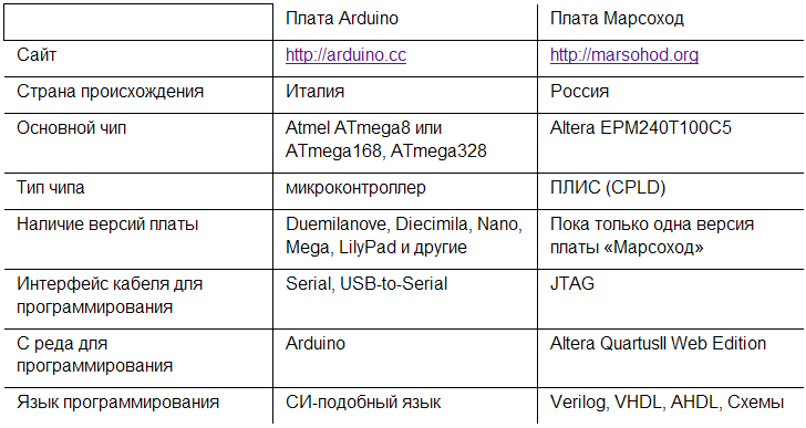
Further, perhaps, to compare the table will not work :-)
Let's just look at some of the technical capabilities of these boards.
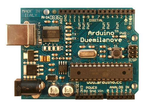
Fee Arduino Duemilanove (ATmega168)
* Power supply: + 5V
* Number of digital inputs / outputs: 14
* Number of analog inputs: 6
* Allowable input / output current 40 mA
* The amount of flash memory: 16 KB
* SRAM volume: 1 KB
* Volume EEPROM: 512 bytes
* Generator frequency: 16 MHz
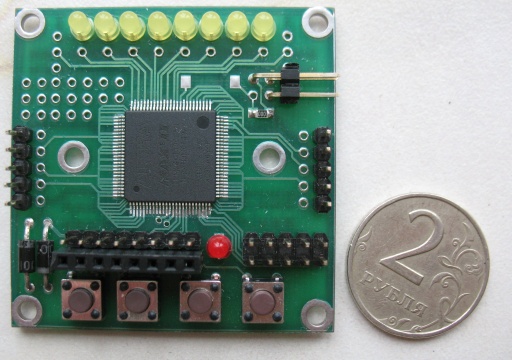
Fee Mars Rover
* Power supply: 2.5-4.6v (VCC)
* Total custom pins: 22
* Of these, increased power (for motors): 6
* Maximum current of one pin - 25 ma
* The maximum current of the "motor" pin - 250 ma
* Input voltage per pin from -0.7V to VCC + 0.7V
* Internal chip generator ~ 5 MHz
* Number of logic elements / triggers: 240
* The amount of flash memory: 512x16 bits = 1024 bytes.
A cursory review of these characteristics of the Mars Rover board is somewhat surprising. In fact, the amount of flash memory is much less than that of ATmega168, SRAM - in general, no. And what is the "number of logical elements / triggers"? And somehow they are few - only 240 ...
Perhaps now we have reached the most important and fundamental difference between these boards. For an Arduino board, you need to write programs in a SI-like language. But for the Mars Rover card, you need to "draw electrical-fundamental circuits." Of course, instead of diagrams, you can use special languages for describing hardware like Verilog or VHDL, but this does not change the essence. A project made for the Mars Rover board is still a circuit design project.
Perhaps those who started with programming microcontrollers will find it all quite difficult. There really is something to think about. In fact, typical programming in a language like SI is a description of the sequential actions of the processor. In FPGA it's not like that. Here it is required to describe many synchronous processes that run in parallel. This is a description of the transfer of data bits from register to register.
I propose to look at specific examples of the most simple projects. We will do the same thing, but on different boards: Arduino and Mars Rover .
For example, take the simple Button example published on the Arduino website.
In this example, the microcontroller periodically polls the state of one input line to which the button is connected. If the button is not pressed, then the input line will have the value “zero” (the line is slightly pulled to ground by a resistor). If the button is pressed, then the line will have a supply voltage, that is, a “one”. The microcontroller writes this value to the port and the connected LED lights up or goes out. In my opinion, this is a great example. Here is a look at its source code:
// constants won't change. They're used here to
// set pin numbers:
const int buttonPin = 2; // the number of the pushbutton pin
const int ledPin = 13; // the number of the LED pin
// variables will change:
int buttonState = 0; // variable for reading the pushbutton status
void setup () {
// initialize the LED pin as an output:
pinMode (ledPin, OUTPUT);
// initialize the pushbutton pin as an input:
pinMode (buttonPin, INPUT);
}
void loop () {
// read the state of the value pushbutton:
buttonState = digitalRead (buttonPin);
// check if the pushbutton is pressed.
// if it is, the buttonState is HIGH:
if (buttonState == HIGH) {
// turn LED on:
digitalWrite (ledPin, HIGH);
}
else {
// turn LED off:
digitalWrite (ledPin, LOW);
}
}
From the program you can see that the microcontroller reads from the port the value of the input where the button is connected and then writes one bit to another port to light the LED.
Honestly, I don’t understand why the creators of this example didn’t write like this:
void loop ()
{
digitalWrite (ledPin, digitalRead (buttonPin));
}
In my opinion so much clearer :-)
It should be noted that since this program is executed by a microcontroller, then of course, between the moments of polling the button state passes time proportional to the number of microprocessor instructions of the entire loop () {...} and its clock frequency.
And now let's see how to do the same thing on the basis of the Mars Rover board. We need to make a project diagram. It will look something like this:
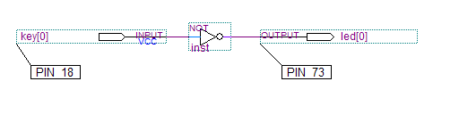
In fact, in our scheme there is only one wire from the input where the button is connected to the output where the LED is connected. Of course there is still a logical element between them - "NOT". He from the signal "zero" makes a "one" and vice versa. This element of the inverter is needed, since the circuit board of the Mars Rover differs from that offered by the Arduino . There the button is connected to the power supply, and the second contact goes to the input of the ATmega168 and is pulled to the ground through a resistor. On the Mars rover board is the opposite. The button is connected to ground, and the second contact goes to the input of the chip and is drawn to the supply voltage through a weak resistor (Weak pull-up resistor). Because of this, the logic turns out to be inverse and you need the element "NOT".
Please note that such a project will "work" much faster than the program in Arduino . Here, the button is not polled by software, but is actually connected by wire through the inverter from the input to the output. The propagation delay will be just a few nanoseconds. Thus, potentially CPLD will be able to perform much faster functions than a microcontroller.
And one more note.
Of course, large projects are not drawn schemes. This is how the same scheme could look, but written in the Verilog hardware programming language:
module test (input wire key, output wire led);
assign led =! key;
endmodule
Perhaps this example with a button will seem stupid to you. There really isn't much sense in it. However, it clarifies the most important thing. When you make a project for a Mars Rover card, you install the necessary logical elements like “AND”, “OR”, “NOT”, as well as a trigger and connect them with wires to the project. Altera QuartusII development environment will automatically place all the logic of your project inside the chip and connect the necessary elements with wires.
In general, you can see. Undoubtedly, both boards deserve attention. Something easier to do on the Arduino platform, something on the Mars Rover platform. Some ideas I think can be implemented on one board and not on the other.
I like the rover more . It makes you think more and do amazing things with seemingly small resources. Be sure to visit this site marsohod.org and at least look at examples of already implemented projects. There are descriptions, you can download the projects themselves and there are videos. The videos show how the robots work, how they are controlled with the help of remote controls, the cars react to the light and leave the labyrinths. And much more!
Where to begin? Perhaps there are two interesting possibilities - this is the Arduino board or the Mars Rover board. I'll try to explain what it is.
')
First of all, both boards were originally designed for electronic modeling - the creation of all kinds of electronic toys, robots, typewriters and other prikolyushek. This is a kind of "electronic designers". With their help, you can learn the basics of circuit design and electronics and programming, or you can create real, useful home automation devices. Interestingly, the schemes of these designer boards are freely available, published by manufacturers on the Internet. There are also a lot of examples of implemented "devices" for Arduino on the Internet.
The rover motherboard is not yet so well known, but its authors themselves make machine-robots and all sorts of toys based on it. All source codes of projects are also on their website in the public domain.
Here we have such a pivot table:
Further, perhaps, to compare the table will not work :-)
Let's just look at some of the technical capabilities of these boards.
Fee Arduino Duemilanove (ATmega168)
* Power supply: + 5V
* Number of digital inputs / outputs: 14
* Number of analog inputs: 6
* Allowable input / output current 40 mA
* The amount of flash memory: 16 KB
* SRAM volume: 1 KB
* Volume EEPROM: 512 bytes
* Generator frequency: 16 MHz
Fee Mars Rover
* Power supply: 2.5-4.6v (VCC)
* Total custom pins: 22
* Of these, increased power (for motors): 6
* Maximum current of one pin - 25 ma
* The maximum current of the "motor" pin - 250 ma
* Input voltage per pin from -0.7V to VCC + 0.7V
* Internal chip generator ~ 5 MHz
* Number of logic elements / triggers: 240
* The amount of flash memory: 512x16 bits = 1024 bytes.
A cursory review of these characteristics of the Mars Rover board is somewhat surprising. In fact, the amount of flash memory is much less than that of ATmega168, SRAM - in general, no. And what is the "number of logical elements / triggers"? And somehow they are few - only 240 ...
Perhaps now we have reached the most important and fundamental difference between these boards. For an Arduino board, you need to write programs in a SI-like language. But for the Mars Rover card, you need to "draw electrical-fundamental circuits." Of course, instead of diagrams, you can use special languages for describing hardware like Verilog or VHDL, but this does not change the essence. A project made for the Mars Rover board is still a circuit design project.
Perhaps those who started with programming microcontrollers will find it all quite difficult. There really is something to think about. In fact, typical programming in a language like SI is a description of the sequential actions of the processor. In FPGA it's not like that. Here it is required to describe many synchronous processes that run in parallel. This is a description of the transfer of data bits from register to register.
I propose to look at specific examples of the most simple projects. We will do the same thing, but on different boards: Arduino and Mars Rover .
For example, take the simple Button example published on the Arduino website.
In this example, the microcontroller periodically polls the state of one input line to which the button is connected. If the button is not pressed, then the input line will have the value “zero” (the line is slightly pulled to ground by a resistor). If the button is pressed, then the line will have a supply voltage, that is, a “one”. The microcontroller writes this value to the port and the connected LED lights up or goes out. In my opinion, this is a great example. Here is a look at its source code:
// constants won't change. They're used here to
// set pin numbers:
const int buttonPin = 2; // the number of the pushbutton pin
const int ledPin = 13; // the number of the LED pin
// variables will change:
int buttonState = 0; // variable for reading the pushbutton status
void setup () {
// initialize the LED pin as an output:
pinMode (ledPin, OUTPUT);
// initialize the pushbutton pin as an input:
pinMode (buttonPin, INPUT);
}
void loop () {
// read the state of the value pushbutton:
buttonState = digitalRead (buttonPin);
// check if the pushbutton is pressed.
// if it is, the buttonState is HIGH:
if (buttonState == HIGH) {
// turn LED on:
digitalWrite (ledPin, HIGH);
}
else {
// turn LED off:
digitalWrite (ledPin, LOW);
}
}
From the program you can see that the microcontroller reads from the port the value of the input where the button is connected and then writes one bit to another port to light the LED.
Honestly, I don’t understand why the creators of this example didn’t write like this:
void loop ()
{
digitalWrite (ledPin, digitalRead (buttonPin));
}
In my opinion so much clearer :-)
It should be noted that since this program is executed by a microcontroller, then of course, between the moments of polling the button state passes time proportional to the number of microprocessor instructions of the entire loop () {...} and its clock frequency.
And now let's see how to do the same thing on the basis of the Mars Rover board. We need to make a project diagram. It will look something like this:
In fact, in our scheme there is only one wire from the input where the button is connected to the output where the LED is connected. Of course there is still a logical element between them - "NOT". He from the signal "zero" makes a "one" and vice versa. This element of the inverter is needed, since the circuit board of the Mars Rover differs from that offered by the Arduino . There the button is connected to the power supply, and the second contact goes to the input of the ATmega168 and is pulled to the ground through a resistor. On the Mars rover board is the opposite. The button is connected to ground, and the second contact goes to the input of the chip and is drawn to the supply voltage through a weak resistor (Weak pull-up resistor). Because of this, the logic turns out to be inverse and you need the element "NOT".
Please note that such a project will "work" much faster than the program in Arduino . Here, the button is not polled by software, but is actually connected by wire through the inverter from the input to the output. The propagation delay will be just a few nanoseconds. Thus, potentially CPLD will be able to perform much faster functions than a microcontroller.
And one more note.
Of course, large projects are not drawn schemes. This is how the same scheme could look, but written in the Verilog hardware programming language:
module test (input wire key, output wire led);
assign led =! key;
endmodule
Perhaps this example with a button will seem stupid to you. There really isn't much sense in it. However, it clarifies the most important thing. When you make a project for a Mars Rover card, you install the necessary logical elements like “AND”, “OR”, “NOT”, as well as a trigger and connect them with wires to the project. Altera QuartusII development environment will automatically place all the logic of your project inside the chip and connect the necessary elements with wires.
In general, you can see. Undoubtedly, both boards deserve attention. Something easier to do on the Arduino platform, something on the Mars Rover platform. Some ideas I think can be implemented on one board and not on the other.
I like the rover more . It makes you think more and do amazing things with seemingly small resources. Be sure to visit this site marsohod.org and at least look at examples of already implemented projects. There are descriptions, you can download the projects themselves and there are videos. The videos show how the robots work, how they are controlled with the help of remote controls, the cars react to the light and leave the labyrinths. And much more!
Source: https://habr.com/ru/post/89585/
All Articles