Creating non-standard database items for nanoCAD SPDS using wall panels as an example (part 2)
We continue the publication on the creation of non-standard elements.
Part one here
')
Following the concept of nanoCAD SPDS and our task setting, there was no point in developing four different sketches for each brand of the panel, since switching between them in the dialogue would not lead to tracking the properties of the selected brand. Therefore, for all the options should develop a single sketch and learn how to manage it from the dialog box. In fig. 4 shows an example of a panel sketch.

Fig. 4. Sketch for wall panel
As can be seen from the figure, almost all sizes are constants. The total length is defined as the variable “Length_panel” and will be assigned in the program by the specified values in the script. The circle crossed out by two segments represents the insertion point of the panel on the drawing. It is precisely positioned according to the layout requirements for the plates in the drawing. To control the thumbnail from the dialog box, you must assign variables to the graphic elements through which this control will be exercised. For our version, it comes down not to a change in the size of the plate, but to a change in the visibility of the individual graphic elements of the sketch. Let us explain this with a concrete example. Fig. 5 represents all four options (brands) of panels; they differ only in shortening from different sides, the other dimensions remain unchanged.

Fig. 5. An example of the display in terms of options brands H-101
Auxiliary red lines are drawn to visually determine the dimensions of the panels. The right indicates the brand of panels (in brackets - the brand of concrete). When you install the sign of the carrier panel appears hatching. Thus, the whole task comes down to setting variables that would be responsible for showing or hiding individual fragments of a sketch in a dialog box, depending on the brand selected. This allows us to do with the only and necessary design for the database object, which is the four brands of the panel. Consider the parameter of one extreme left segment of the sketch. The dialog box for defining parameters is shown in fig. 6
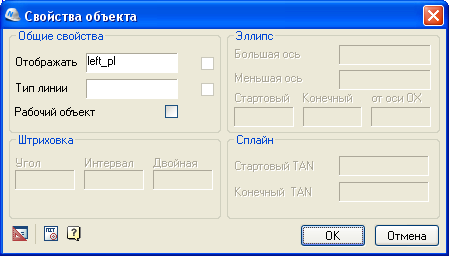
Fig. 6. Properties of the graphic primitive for the sketch
The Display field contains the variable “left_pl”, which is assigned a value in the dialog. When the value is “1”, the segment is displayed in the sketch, and if the value is “0”, it is not. Depending on the specific situation, each sketch primitive is assigned one or several variables that are responsible for displaying this primitive under certain conditions. For more complex cases, additional parameters can be specified in this window — for example, line type, hatching parameters, and so on. For the segment defining the axis of symmetry, the “Work object” parameter is set, which hides the axis in the drawing. For different versions of the panels, their sketches and their drawing algorithms were developed, but in any case, one sketch is created for each database object. Now let's see how variables are managed in the dialog box.
The work of a form or dialog box is controlled by a script, that is, in fact, the program code on which the database object is running. In the simplest cases, it is formed automatically using the Script Wizard. With this tool, the user goes through a step-by-step procedure for determining all the necessary variables and many other properties of the object. Fig. 7 shows an example of the Script Wizard dialog box at the step of defining variables. In the left window displays a list of variables. The properties of the active variable pointed to by the cursor are shown in the center, and the script text is generated at the bottom.
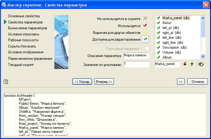
Fig. 7. Script Wizard window on variable properties step
Having passed all stages, the user receives the finished object. In the Object Wizard window, the assigned variables needed to build the object are visible. In fig. 8 the display of table variables is activated, the properties of which are assigned when moving through the rows of the table. In other words, when we switch between the names of the panel brands in the dialog window, all the corresponding panel properties in the given row of the table change.

Fig. 8. Object wizard window with table variables.
This is the solution non-standard, which is usually not used in simple objects. Other variables can be open and protected, they are assigned in the text of the script. If a variable has the same value regardless of the panel's brand, you can assign it a constant value. For a panel, this may be, for example, a method of exterior finishing or belonging to an album of drawings. We will see these properties later in the specification, but they are also assigned in the script, and are stored in the object in the drawing. For our non-standard case, the Script Wizard can help form variables, but not a dialog box. In the general case, you can write the script yourself from the very beginning, without a Wizard, but it is much easier to make a blank and then correct it in text mode.
For placing an extended set of controls in a dialog box — for example, drop-down lists, variable tables, switches, etc. - Custom form is required. Unlike the standard form, which is generated using a script without user intervention, a user form is created using the Form Editor. An example of the window of this Editor is shown in Fig. 9

Fig. 9. Shape Editor Window for Wall Panel
The form editor is very similar to many editors from object programming languages. With the help of toolbars located in the upper part, added controls. The desired position from the Variables window can be dragged onto the form field, while selecting the type of control to which this variable will be assigned. By activating the stamped element, you can control it through the element properties window. To replace the standard form when calling an object from the user base, you need to write an additional command in the script and comment out the call to the standard form. We will omit purely technical details, noting that solving more complex tasks when creating non-trivial objects requires (in terms of their behavior and description) some intervention in the text of the script. Thus, we have described the necessary variables and defined them in the process of inserting an element into the drawing. All values are stored in the object and can be changed at any time by double-clicking through the dialog box. This gives the work some flexibility when it is required to make changes to the nanoCAD DPS database object without redrawing.
Now our item is ready for use in the project. But it is not enough just to put the panel on the plan. It is necessary to put down the marking and enter it into the specification. These problems will be solved in the final third part of our publication.
Alexey Tsvetkov, Tsvetkov@nanocad.ru
Part three
Part one here
')
Creating a sketch
Following the concept of nanoCAD SPDS and our task setting, there was no point in developing four different sketches for each brand of the panel, since switching between them in the dialogue would not lead to tracking the properties of the selected brand. Therefore, for all the options should develop a single sketch and learn how to manage it from the dialog box. In fig. 4 shows an example of a panel sketch.
Fig. 4. Sketch for wall panel
As can be seen from the figure, almost all sizes are constants. The total length is defined as the variable “Length_panel” and will be assigned in the program by the specified values in the script. The circle crossed out by two segments represents the insertion point of the panel on the drawing. It is precisely positioned according to the layout requirements for the plates in the drawing. To control the thumbnail from the dialog box, you must assign variables to the graphic elements through which this control will be exercised. For our version, it comes down not to a change in the size of the plate, but to a change in the visibility of the individual graphic elements of the sketch. Let us explain this with a concrete example. Fig. 5 represents all four options (brands) of panels; they differ only in shortening from different sides, the other dimensions remain unchanged.
Fig. 5. An example of the display in terms of options brands H-101
Auxiliary red lines are drawn to visually determine the dimensions of the panels. The right indicates the brand of panels (in brackets - the brand of concrete). When you install the sign of the carrier panel appears hatching. Thus, the whole task comes down to setting variables that would be responsible for showing or hiding individual fragments of a sketch in a dialog box, depending on the brand selected. This allows us to do with the only and necessary design for the database object, which is the four brands of the panel. Consider the parameter of one extreme left segment of the sketch. The dialog box for defining parameters is shown in fig. 6
Fig. 6. Properties of the graphic primitive for the sketch
The Display field contains the variable “left_pl”, which is assigned a value in the dialog. When the value is “1”, the segment is displayed in the sketch, and if the value is “0”, it is not. Depending on the specific situation, each sketch primitive is assigned one or several variables that are responsible for displaying this primitive under certain conditions. For more complex cases, additional parameters can be specified in this window — for example, line type, hatching parameters, and so on. For the segment defining the axis of symmetry, the “Work object” parameter is set, which hides the axis in the drawing. For different versions of the panels, their sketches and their drawing algorithms were developed, but in any case, one sketch is created for each database object. Now let's see how variables are managed in the dialog box.
Dialog box with object variables
The work of a form or dialog box is controlled by a script, that is, in fact, the program code on which the database object is running. In the simplest cases, it is formed automatically using the Script Wizard. With this tool, the user goes through a step-by-step procedure for determining all the necessary variables and many other properties of the object. Fig. 7 shows an example of the Script Wizard dialog box at the step of defining variables. In the left window displays a list of variables. The properties of the active variable pointed to by the cursor are shown in the center, and the script text is generated at the bottom.
Fig. 7. Script Wizard window on variable properties step
Having passed all stages, the user receives the finished object. In the Object Wizard window, the assigned variables needed to build the object are visible. In fig. 8 the display of table variables is activated, the properties of which are assigned when moving through the rows of the table. In other words, when we switch between the names of the panel brands in the dialog window, all the corresponding panel properties in the given row of the table change.
Fig. 8. Object wizard window with table variables.
This is the solution non-standard, which is usually not used in simple objects. Other variables can be open and protected, they are assigned in the text of the script. If a variable has the same value regardless of the panel's brand, you can assign it a constant value. For a panel, this may be, for example, a method of exterior finishing or belonging to an album of drawings. We will see these properties later in the specification, but they are also assigned in the script, and are stored in the object in the drawing. For our non-standard case, the Script Wizard can help form variables, but not a dialog box. In the general case, you can write the script yourself from the very beginning, without a Wizard, but it is much easier to make a blank and then correct it in text mode.
For placing an extended set of controls in a dialog box — for example, drop-down lists, variable tables, switches, etc. - Custom form is required. Unlike the standard form, which is generated using a script without user intervention, a user form is created using the Form Editor. An example of the window of this Editor is shown in Fig. 9
Fig. 9. Shape Editor Window for Wall Panel
The form editor is very similar to many editors from object programming languages. With the help of toolbars located in the upper part, added controls. The desired position from the Variables window can be dragged onto the form field, while selecting the type of control to which this variable will be assigned. By activating the stamped element, you can control it through the element properties window. To replace the standard form when calling an object from the user base, you need to write an additional command in the script and comment out the call to the standard form. We will omit purely technical details, noting that solving more complex tasks when creating non-trivial objects requires (in terms of their behavior and description) some intervention in the text of the script. Thus, we have described the necessary variables and defined them in the process of inserting an element into the drawing. All values are stored in the object and can be changed at any time by double-clicking through the dialog box. This gives the work some flexibility when it is required to make changes to the nanoCAD DPS database object without redrawing.
Now our item is ready for use in the project. But it is not enough just to put the panel on the plan. It is necessary to put down the marking and enter it into the specification. These problems will be solved in the final third part of our publication.
Alexey Tsvetkov, Tsvetkov@nanocad.ru
Part three
Source: https://habr.com/ru/post/88635/
All Articles