Creating non-standard database elements for nanoCAD SPDS on the example of wall panels (part 1)
We decided to make several publications “specialized”, that is, those where we will talk about working with our products and nothing more, without pretending to be massive, but in an attempt to find our users who definitely are here. And we will talk about real projects, will be told either by the users themselves, or our products, directly working with products.
The first article (will be in three parts) is devoted to nanoCAD SPDS - CAD for computer-aided design in construction.
Staroverov Design Workshop is a Russian company engaged in the design, modernization and improvement of residential multi-panel and monolithic residential buildings. For these buildings, the organization performs the entire cycle of design work. Acquiring nanoCAD SPDS, the workshop would like to automate the layout and specification of wall panels, along with automating the process of drawing up building drawings. This is the most time-consuming, key task of the construction department, for the solution of which the department received several licenses of nanoCAD SPDS .
The organization has a huge number of developments and uses the widest range of wall panels of various types. Among the main ones are internal wall panels of the floor and technical floors, facing panels, panels of the technical underground, as well as typical and shortened floors and technical underground. Note that the vast majority of descriptions, drawings and specifications of these panels were presented in paper form.
The department was tasked to provide designers with the opportunity to visually select panels from the nanoCAD DPS database, place the panels on the drawing, label and obtain the specification.
The first thing you had to face was the unstructured and fragmented documentation on the description of the panels. The workshop staff did a great job of dividing the total mass of elements into separate groups and subgroups with many levels of hierarchy. When it became clear on what principle to create the base structure, it was possible to formulate the selection criteria from the base in the process of placing the panels in the drawing. In turn, these criteria determined the appearance of the database element window with the corresponding fields. According to the finished specification form and additional conditions for its creation, the necessary additional properties were clarified, which each wall panel should have been assigned to ensure the correct formation of the table form. At the last stage, it was necessary to label the panels in the drawing. In more detail the solution of all these problems we will present below.
')
In the general case, the created element of the nanoCAD DPS database looks as follows. First of all, a sketch at a scale of 1: 1 is created, which serves as a prototype of the image of the object in the drawing. It corresponds to special rules, and certain properties are assigned to its lines and other primitives. Each geometric value of the sketch must be dimensioned. If it is not intended to change the value, the usual size is indicated with the value obtained. If the size remains the variable value, it is assigned the corresponding variable. Set other properties of the sketch. nanoCAD SPDS allows for each database element to create several versions (variants), and for each of them up to six types in all projections, respectively.
The projections are determined by the direction of the object: view in plan, left, rear, bottom, etc. Each of the six projections can be assigned a refinement of the form: for example, “hidden view” or “section view”. That is, within the same element of the base, we can create several versions and for each indicate the necessary flat projections that can be selected and inserted into the drawing. When inserting an object from a database, all its variable geometric values, additional properties that may be included in the specification, and other attributes are indicated. Let us explain this on the standard element nanoCAD SPDS - front column. An example of the element insertion window is shown in fig. 1 .
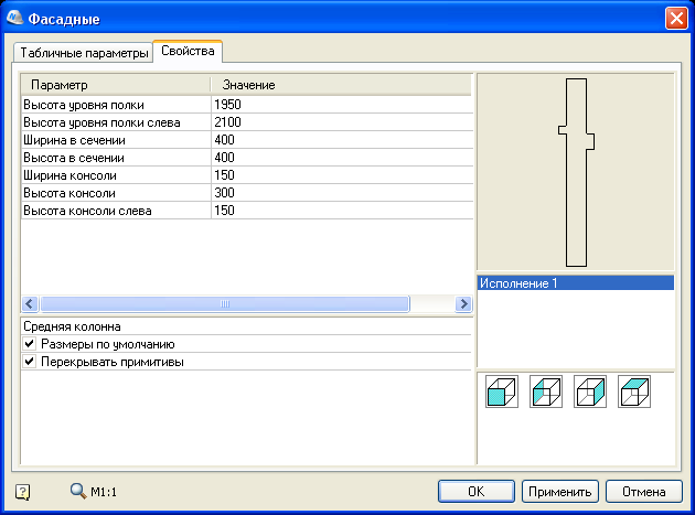
Fig. 1. Window inserts facade columns
In the lower right corner shows the projection of a single execution for this column. Clicking on the appropriate view, we switch to it, and the view itself appears in the preview window. Before inserting a view into a drawing, it is necessary to clarify the parameters indicated on the left. On the tab of the tabular parameters, the values defined by the tables are set: unlike the usual parameters, we can only select predefined values, and not enter arbitrary ones. In confirmation of the fact that our wall panels were just non-standard elements, we’ll dwell in more detail on the issue of sketching for an object.
A specific sketch is assigned to each view in order to uniquely display an object in a given projection. Open the base element in the Object Wizard and switch to the section for defining performances. In this case, there is only one "Execution 1". If you wish, you can rename it. Four types are defined for it. Each type is assigned certain sketches. The preview is formed according to these sketches. View visualization can be changed. If you right-click to bring up the context menu, then, pointing to the view, you can select the items Assign a picture from objects or Import a picture from a graphic file . In the first case, we generate a picture from arbitrary drawing objects, and in the second, from a bitmap image. In fig. 2 you can see an example of editing in the Object Wizard.
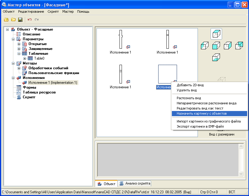
Fig. 2. Window of the Object Wizard for the “Facade Column” Element
In the formulation of the problem it is said that the designers place on the drawing only a plan view of each of the wall panels. At first it was assumed that the task is greatly simplified. The division of the general panel nomenclature within the framework of a strict hierarchy should have combined up to four panel variants into one element of the database. For example, one panel could be presented in four versions: normal, shortened on the left, shortened on the right, and shortened on both sides. It only remained to create these performances in this database object. For each performance, a single type in the plan is enough, to which we must add a few additional parameters and properties that are output to the specification ... But everything turned out to be much more complicated.
The fact is that these are not four variants of one brand of panel, but different brands of four different panels. If not to make such a union, the number of base elements would be equal to the number of panel brands, and this is unacceptable to work with so many elements. The ideology of the nanoCAD DPS assumes that one database object is one brand. When changing the performance, we change only the external geometric characteristics of the object, but not its properties, such as, for example, the brand name and volume, which in our case are unique for different panel designs. It turns out that, acting in a standard way, there is no possibility to combine several brands of panels in one base object, although, in fact, they are only variants of the same brand.
Creating a custom item was dictated by another customer requirement. When switching between versions (in our case, brands) of panels, the designer must simultaneously see the side view, in plan and in section. This task was decided by assigning a sketch to a raster preview. At the same time, the standard preview window is very small and is located in a very small area of the dialogue - a large and rich drawing of three types of panel would be simply unreadable there. This and a number of other reasons led to the idea of creating a custom dialog using the Form Editor. An example of a finished window with control elements for the H-101, N-101 yk , N-101 uklev and N-101 ukp panels is shown in fig. 3 In this case, all brands are actually variants of the brand H-101.

Fig. 3. Dialog box for the element of wall panels of brands N-101
When switching between brand names of panels, the drawing in the dialog box automatically changes, which allows the designer to visually evaluate the selected panel in the three drawing views. Panel volume is automatically assigned. It is necessary to specify only the brand of concrete, the sign of the supporting panel and the belonging of a section of the building by selecting the desired number from the drop-down list. After this, the required view is placed in the plan.
This concludes the first part of our article. In the next publication, we will proceed directly to creating a non-standard wall panel. We decided on the main requirements for the element. Now we have to work on the elaboration of a sketch and a dialog box.
Alexey Tsvetkov, Tsvetkov@nanocad.ru
Part two
Part three
The first article (will be in three parts) is devoted to nanoCAD SPDS - CAD for computer-aided design in construction.
Formulation of the problem
Staroverov Design Workshop is a Russian company engaged in the design, modernization and improvement of residential multi-panel and monolithic residential buildings. For these buildings, the organization performs the entire cycle of design work. Acquiring nanoCAD SPDS, the workshop would like to automate the layout and specification of wall panels, along with automating the process of drawing up building drawings. This is the most time-consuming, key task of the construction department, for the solution of which the department received several licenses of nanoCAD SPDS .
The organization has a huge number of developments and uses the widest range of wall panels of various types. Among the main ones are internal wall panels of the floor and technical floors, facing panels, panels of the technical underground, as well as typical and shortened floors and technical underground. Note that the vast majority of descriptions, drawings and specifications of these panels were presented in paper form.
The department was tasked to provide designers with the opportunity to visually select panels from the nanoCAD DPS database, place the panels on the drawing, label and obtain the specification.
Elaboration of the problem solving algorithm
The first thing you had to face was the unstructured and fragmented documentation on the description of the panels. The workshop staff did a great job of dividing the total mass of elements into separate groups and subgroups with many levels of hierarchy. When it became clear on what principle to create the base structure, it was possible to formulate the selection criteria from the base in the process of placing the panels in the drawing. In turn, these criteria determined the appearance of the database element window with the corresponding fields. According to the finished specification form and additional conditions for its creation, the necessary additional properties were clarified, which each wall panel should have been assigned to ensure the correct formation of the table form. At the last stage, it was necessary to label the panels in the drawing. In more detail the solution of all these problems we will present below.
')
Standard database item
In the general case, the created element of the nanoCAD DPS database looks as follows. First of all, a sketch at a scale of 1: 1 is created, which serves as a prototype of the image of the object in the drawing. It corresponds to special rules, and certain properties are assigned to its lines and other primitives. Each geometric value of the sketch must be dimensioned. If it is not intended to change the value, the usual size is indicated with the value obtained. If the size remains the variable value, it is assigned the corresponding variable. Set other properties of the sketch. nanoCAD SPDS allows for each database element to create several versions (variants), and for each of them up to six types in all projections, respectively.
The projections are determined by the direction of the object: view in plan, left, rear, bottom, etc. Each of the six projections can be assigned a refinement of the form: for example, “hidden view” or “section view”. That is, within the same element of the base, we can create several versions and for each indicate the necessary flat projections that can be selected and inserted into the drawing. When inserting an object from a database, all its variable geometric values, additional properties that may be included in the specification, and other attributes are indicated. Let us explain this on the standard element nanoCAD SPDS - front column. An example of the element insertion window is shown in fig. 1 .
Fig. 1. Window inserts facade columns
In the lower right corner shows the projection of a single execution for this column. Clicking on the appropriate view, we switch to it, and the view itself appears in the preview window. Before inserting a view into a drawing, it is necessary to clarify the parameters indicated on the left. On the tab of the tabular parameters, the values defined by the tables are set: unlike the usual parameters, we can only select predefined values, and not enter arbitrary ones. In confirmation of the fact that our wall panels were just non-standard elements, we’ll dwell in more detail on the issue of sketching for an object.
A specific sketch is assigned to each view in order to uniquely display an object in a given projection. Open the base element in the Object Wizard and switch to the section for defining performances. In this case, there is only one "Execution 1". If you wish, you can rename it. Four types are defined for it. Each type is assigned certain sketches. The preview is formed according to these sketches. View visualization can be changed. If you right-click to bring up the context menu, then, pointing to the view, you can select the items Assign a picture from objects or Import a picture from a graphic file . In the first case, we generate a picture from arbitrary drawing objects, and in the second, from a bitmap image. In fig. 2 you can see an example of editing in the Object Wizard.
Fig. 2. Window of the Object Wizard for the “Facade Column” Element
Design custom item
In the formulation of the problem it is said that the designers place on the drawing only a plan view of each of the wall panels. At first it was assumed that the task is greatly simplified. The division of the general panel nomenclature within the framework of a strict hierarchy should have combined up to four panel variants into one element of the database. For example, one panel could be presented in four versions: normal, shortened on the left, shortened on the right, and shortened on both sides. It only remained to create these performances in this database object. For each performance, a single type in the plan is enough, to which we must add a few additional parameters and properties that are output to the specification ... But everything turned out to be much more complicated.
The fact is that these are not four variants of one brand of panel, but different brands of four different panels. If not to make such a union, the number of base elements would be equal to the number of panel brands, and this is unacceptable to work with so many elements. The ideology of the nanoCAD DPS assumes that one database object is one brand. When changing the performance, we change only the external geometric characteristics of the object, but not its properties, such as, for example, the brand name and volume, which in our case are unique for different panel designs. It turns out that, acting in a standard way, there is no possibility to combine several brands of panels in one base object, although, in fact, they are only variants of the same brand.
Creating a custom item was dictated by another customer requirement. When switching between versions (in our case, brands) of panels, the designer must simultaneously see the side view, in plan and in section. This task was decided by assigning a sketch to a raster preview. At the same time, the standard preview window is very small and is located in a very small area of the dialogue - a large and rich drawing of three types of panel would be simply unreadable there. This and a number of other reasons led to the idea of creating a custom dialog using the Form Editor. An example of a finished window with control elements for the H-101, N-101 yk , N-101 uklev and N-101 ukp panels is shown in fig. 3 In this case, all brands are actually variants of the brand H-101.
Fig. 3. Dialog box for the element of wall panels of brands N-101
When switching between brand names of panels, the drawing in the dialog box automatically changes, which allows the designer to visually evaluate the selected panel in the three drawing views. Panel volume is automatically assigned. It is necessary to specify only the brand of concrete, the sign of the supporting panel and the belonging of a section of the building by selecting the desired number from the drop-down list. After this, the required view is placed in the plan.
This concludes the first part of our article. In the next publication, we will proceed directly to creating a non-standard wall panel. We decided on the main requirements for the element. Now we have to work on the elaboration of a sketch and a dialog box.
Alexey Tsvetkov, Tsvetkov@nanocad.ru
Part two
Part three
Source: https://habr.com/ru/post/88435/
All Articles