How to inexpensively fix the mat. card or video card
Hi Habr, recently read the article “How I Roasted a Video Card” and would like to express my IMHO on this occasion and offer my own version, which I have been using for a long time. I would like to warn against the consequences that may arise after reading the above-mentioned article, namely: overheating, blown-up capacitors and completely killed fried boards. Comrades! Do not overdo it! This method is more expensive, but the risk of killing the board is much lower.
(careful traffic)
But for the beginning of the theory.
')
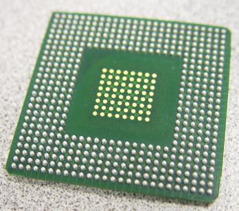 BGA (Ball grid array - an array of balls) - body type of surface-mounted integrated circuits. BGA pins are solder balls deposited on pads on the back of a chip. The microcircuit is placed on the printed circuit board, according to the marking of the first contact on the microcircuit and on the circuit board. Next, the chip is heated using a soldering station or an infrared source, so that the balls begin to melt. Surface tension causes the molten solder to fix the microcircuit exactly above the place where it should be on the board. The combination of a specific solder, soldering temperature, flux and solder mask does not allow the balls to completely deform. BGA is the solution to the problem of producing a miniature IP case with a large number of leads. Output arrays using two-line-sided (SOIC) surface mounting are produced with less and less distance and width of terminals to reduce the space occupied by the terminals, but this causes certain difficulties when installing these components. The conclusions are too close, and the reject rate is growing due to the soldering of the neighboring legs. BGA does not have such a problem - the solder is applied at the factory in the right amount and place.
Availability of BGA chips in all video cards, motherboards, etc. implies a damage to BGA installation, namely: damage due to mechanical effects of soldered joints, tearing balls off the circuit board, tearing balls off the chip itself, damage to the circuit board, namely, tearing the pad from the circuit board. Due to overheating, as well as mechanical loads, damage to the chip itself is possible, which happens much more often and looks similar to the consequences of damaged installation. Consider the causes of damage and their solutions in more detail:
There are the following ways to solve the above problems, namely: replacing the chip, warming up the chip and reboling the chip. Warming up of the chip, as well as dismantling the chip and soldering the chip, is performed on specialized soldering equipment and in no case, either hair dryers, or stoves, or other artisanal devices, which can lead to subsequent damage to the motherboard and the impossibility of further repairs.
Warming up the chip consists in placing a minimum amount of specialized without a flushing flux under the chip, followed by heating the chip at the soldering station, before melting the bga balls with the installation and compulsory keeping of the thermal profile of the chip. Reballing (accurate translation from English. Pereharovka) consists in dismantling the chip, replacing contact balls with special stencils and a special stove, and then installing the chip back onto the motherboard. Replacing a chip is accordingly installing a new chip in exchange for a damaged or suspicious one.
I will not dwell on all methods of repair, but will only touch on warming up. It does not require in-depth knowledge and expensive equipment. Warming up BGA chips. It only helps if the defective ball falls off the pads on the motherboard and the damage site is not strongly oxidized, if the ball falls off from the chip itself as in the above drawings, warming up will not help because of the soldering technology, namely the initial melting of balls occurs due to the warming up of the chip itself. The method is extremely unreliable and undesirable because of the impossibility of visual control. In addition, partial recovery and manifestation of the problem is possible in a short time.
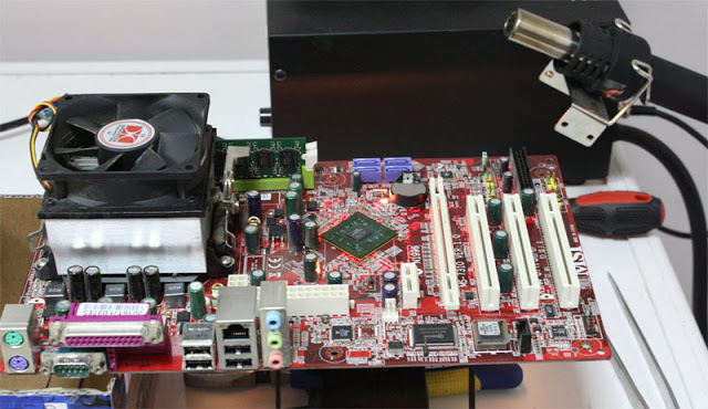
I have an MSI MS-7310 K9N4 Ultra-F motherboard with signs of a non-soldering south bridge (when pressed, the board starts up).
It is necessary to solder the YuM. For this we need:
Having previously removed the radiator, we lubricate the BGA chip with a flux (it is BGA and in no case can I use rosin or LTI-120). For this, I use a syringe. The flux should "blow" under the chip, for this you can use a hairdryer (I use a soldering station)

A small digression. To warm up, I use a 150 watt halogen spotlight (160 rubles), it is able to warm up the board to 200 - 230 degrees. This is exactly the temperature we need, it does not damage the chip and the board and at the same time melts the balls on the board

Install the board and turn on the spotlight (for effect, the board can be covered with a sheet of paper)
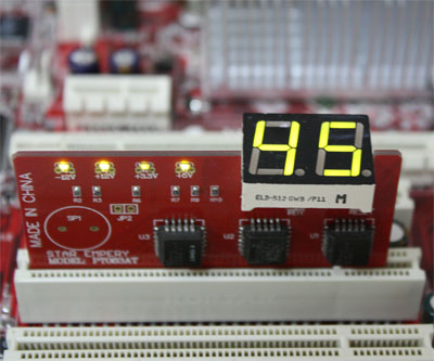
It is necessary to warm up until SMD components float near the chip. You can check this by poking them with a needle or tweezers.

Next, let the board cool down and wash it with any non-aqueous solvent of fats (I use 646th solvent or acetone, less often alcohol). We put the radiator, check installed in the case.
PS I would like to add: If in doubt! Take it to a good service center.
(careful traffic)
But for the beginning of the theory.
Basics of BGA Editing
')
BGA (Ball grid array - an array of balls) - body type of surface-mounted integrated circuits. BGA pins are solder balls deposited on pads on the back of a chip. The microcircuit is placed on the printed circuit board, according to the marking of the first contact on the microcircuit and on the circuit board. Next, the chip is heated using a soldering station or an infrared source, so that the balls begin to melt. Surface tension causes the molten solder to fix the microcircuit exactly above the place where it should be on the board. The combination of a specific solder, soldering temperature, flux and solder mask does not allow the balls to completely deform. BGA is the solution to the problem of producing a miniature IP case with a large number of leads. Output arrays using two-line-sided (SOIC) surface mounting are produced with less and less distance and width of terminals to reduce the space occupied by the terminals, but this causes certain difficulties when installing these components. The conclusions are too close, and the reject rate is growing due to the soldering of the neighboring legs. BGA does not have such a problem - the solder is applied at the factory in the right amount and place.What is the cause of breakdowns?
Availability of BGA chips in all video cards, motherboards, etc. implies a damage to BGA installation, namely: damage due to mechanical effects of soldered joints, tearing balls off the circuit board, tearing balls off the chip itself, damage to the circuit board, namely, tearing the pad from the circuit board. Due to overheating, as well as mechanical loads, damage to the chip itself is possible, which happens much more often and looks similar to the consequences of damaged installation. Consider the causes of damage and their solutions in more detail:
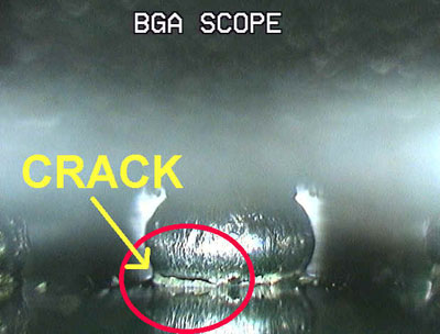
- A typical case of damage to the BGA assembly, the ball is cut off from the motherboard, there is poor contact or no contact at all. It is restored by rebooling and warming up, while warming up, the problem may recur if the sites of damage are oxidized and flux processing is impossible, and the problem may be repeated because of the following damage in other places.
- At least a typical case, the separation of the balls from the pads, the balls remain on the motherboard. The most common option. The chip itself from which the balls fell off and the pads are oxidized (oxidation occurs very quickly), a thin layer of the chip pad is on the balls, all this is also oxidized. Warming up in this case is impossible, only reballing.
- A rarer case, but also quite common, namely because of poor-quality printed circuit boards, as well as mechanical damage, the landing pads from the motherboard are broken along with the balls. In this case, in addition to the chip reboling, the restoration of contact pads is required, and the warm-up is correspondingly useless.
- The last option, namely the damage of the BGA chip itself. In this case, due to mechanical damage, and more often, overheating of the chip itself, the following occurs: The chip crystal begins to peel off directly from the chip case, micro cracks appear in the chip itself and internal interlayer connections. Neither warm-up nor reballing will help in this case, chip replacement is unique. Visually and even under a microscope, damage is not detected, except when the surface of the chip is slightly swollen due to overheating. With a slight click on the chip, the laptop may even turn on. There is also the possibility of damage to the motherboard itself, namely, damage to interlayer connections, metalized holes and microcracks, but this is usually an unlikely event, and although it cannot be excluded, I do not consider it, since only one solution is to replace the board.
There are the following ways to solve the above problems, namely: replacing the chip, warming up the chip and reboling the chip. Warming up of the chip, as well as dismantling the chip and soldering the chip, is performed on specialized soldering equipment and in no case, either hair dryers, or stoves, or other artisanal devices, which can lead to subsequent damage to the motherboard and the impossibility of further repairs.
Warming up the chip consists in placing a minimum amount of specialized without a flushing flux under the chip, followed by heating the chip at the soldering station, before melting the bga balls with the installation and compulsory keeping of the thermal profile of the chip. Reballing (accurate translation from English. Pereharovka) consists in dismantling the chip, replacing contact balls with special stencils and a special stove, and then installing the chip back onto the motherboard. Replacing a chip is accordingly installing a new chip in exchange for a damaged or suspicious one.
I will not dwell on all methods of repair, but will only touch on warming up. It does not require in-depth knowledge and expensive equipment. Warming up BGA chips. It only helps if the defective ball falls off the pads on the motherboard and the damage site is not strongly oxidized, if the ball falls off from the chip itself as in the above drawings, warming up will not help because of the soldering technology, namely the initial melting of balls occurs due to the warming up of the chip itself. The method is extremely unreliable and undesirable because of the impossibility of visual control. In addition, partial recovery and manifestation of the problem is possible in a short time.
Let's start ...
I have an MSI MS-7310 K9N4 Ultra-F motherboard with signs of a non-soldering south bridge (when pressed, the board starts up).
It is necessary to solder the YuM. For this we need:
- Halogen spotlight
- Washless BGA Flux
- Hair dryer
- / dev / hands or pryamieruki.dll
Preparing a board and a place to warm up
Having previously removed the radiator, we lubricate the BGA chip with a flux (it is BGA and in no case can I use rosin or LTI-120). For this, I use a syringe. The flux should "blow" under the chip, for this you can use a hairdryer (I use a soldering station)
Board installation
A small digression. To warm up, I use a 150 watt halogen spotlight (160 rubles), it is able to warm up the board to 200 - 230 degrees. This is exactly the temperature we need, it does not damage the chip and the board and at the same time melts the balls on the board
Install the board and turn on the spotlight (for effect, the board can be covered with a sheet of paper)
Process…
It is necessary to warm up until SMD components float near the chip. You can check this by poking them with a needle or tweezers.
Next, let the board cool down and wash it with any non-aqueous solvent of fats (I use 646th solvent or acetone, less often alcohol). We put the radiator, check installed in the case.
Is done
PS I would like to add: If in doubt! Take it to a good service center.
Source: https://habr.com/ru/post/88136/
All Articles