3D printing and other rapid prototyping systems
3D printing and other rapid prototyping systems
A little more than a week ago an article on this topic appeared on Habré, but it poorly covered the technical side of printing and caused quite a large number of questions. What I will try to fix in this post.
Three-dimensional printing is one of the methods of rapid prototyping. There are now dozens of rapid prototyping methods. All of them are different from each other, but consist in layering the composite material and can significantly reduce the time needed to make models for visualization, fitting, tooling and other applications, which provides:
- shortened development cycle;
- design improvement;
- quality improvement;
- reduction of product and production prices;
- acceleration of changes in the design.
The main advantage is the ability to create products with only geometric model.
In this case, the product is created at one time, and there is no need to plan the sequence of technological processes. However, compared with CNC machines, the choice of material for the product is very limited.
')
The technology of forming products by gradually increasing the material appeared around the beginning of the 1980s. The process is based on 3 stages: the formation of the cross-section, layer-by-layer overlay sections and the combination of layers. That is, to create a product you need to know only the cross section. This solves some of the problems of creating products:
- There is no need for topological design and transformation of structural elements into elements of manufacture. Cross sections are generated only on the basis of the model.
- Manufacturing parts at a time to minimize the amount of equipment.
- It is not necessary to determine the geometry of the empty space, since the material is being added, not removed.
- There is no need to design the design of fasteners and clips.
- The process is toolless, therefore there is no need to develop additional equipment.
There are several ways to create and combine cross-section layers:
3D printing
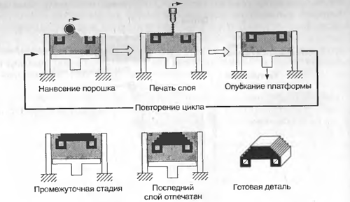
It was developed at the Massachusetts Institute of Technology and got its name because of its similarity to printing with an ordinary printer. The process is as follows:
- A layer of ceramic powder is applied to the platform.
- The print head applies a special binder, due to which particles adhere to each other and form the desired cross-section
- The platform is lowered by one layer thickness and material is applied on it.
- Applying a binder to a new layer and gluing it to the first layer.
- Execution is necessary number of repetitions.
- Additional heat treatment during which the item finally hardens.
Solid Base Curing (SGC-Solid Ground Curing)
Each layer is cured by exposure to an ultraviolet lamp. In this case, all points of the layer harden at the same time, and final curing is not required. The process consists of the following steps:
- For a given geometric model and the desired layer thickness, a set of cross sections is calculated;
- For each layer, an optical mask is made according to the cross-sectional shape;
- The platform is covered with liquid photopolymer;
- A mask corresponding to the cross section is placed above the polymer layer and the plastic is exposed to an ultraviolet lamp;
- Remove remaining fluid;
- Void filling with liquid wax. After hardening, the layer is grinded to the required thickness with a grinding disc;
- The product is covered with a layer of liquid polymer and the process is repeated until the finished product is obtained;
- Frozen wax is melted and removed from the product.
The advantage of the method is that there is no need for additional supports, since all voids are filled with wax. Also, due to uniform ultraviolet irradiation, greater homogeneity of the product is achieved and additional curing is not required.

Stereolithography (Laser Stereolithography)
- The term was introduced by C. Hull, who founded in 1986 the 3D Systems corporation for the production of this equipment. The manufacturing process includes:
- The photopolymerizable composition is poured into the bath and a platform capable of moving in the vertical direction at a depth equal to the layer thickness is placed in the same bath.
- The UV laser scans the polymer layer, hardening the polymer in cross-sectional shape.
- The platform is lowered to the thickness of one layer and conduct a new surface scan. This is repeated until the finished part.
- Additional curing is performed for final curing. This is necessary because. That in each layer may remain liquid areas. Since the size of the laser beam is finite, the process can be compared with painting the figure with a ballpoint pen.
The method is one of the most popular, but if the part has a cut-out below, the creation of supporting structures is required. As a result, the finished product surface roughness without any treatment does not exceed 100 microns. Cured FPC is easily polished. The strength of finished parts is comparable to the strength of hardened epoxy resin products. Finished models can withstand heat up to 100ْ without changing the shape and size.

where 1 is a laser; 2 - product; 3 - liquid monomer; 4 - bath; 5 - mobile platform; 6 is the mirror controlling the scanning; 7 - leveling knife.
Selective Laser Sintering (SLS - Selective Laser Sintering)
The process is developed by the American company DTM and is as follows:
- Powdered material is applied to the platform with a special leveling roller;
- The powder layer is selectively scanned and heated by a laser beam. As a result, the particles stick together among themselves and form the desired cross-section of the product;
- The platform is lowered by the thickness of one layer and powder material is applied to it;
- The laser scans again, causing the particles and layers to stick together;
- Steps three and four are repeated until the desired product is received;
- Some materials require additional sintering.
Additional supporting structures are not required due to the filling of voids with powder. The advantage of the method is the possibility of using any fusible powder, including metal. The method is mainly used for the manufacture of molds with a resource of from 2500 to 10000 products.
where 1 is a laser, 2 is an optical system, 3 is a finished product, 4 is a movable (Z-axis) work platform, 5 are bunkers for feeding powder material, 6 is powder material, 7 is a movable bunker table, 8 is a feed roller powder and leveling layer
Lamination (LOM - Laminated Object Modeling)
The part is obtained by lamination and laser cutting of the incoming sheet material. Adhesion occurs due to thermo-adhesive coating.
- Each sheet is glued to the workpiece with heat and pressure. The sheet material is fed as a continuous roll on one side and taken on the other side. The required temperature and pressure are provided by the rolling roller. Moreover, when gluing a new film layer, the support platform shifts down to the value of the film thickness;
- After the sheet is attached, it is scanned along the contour of the cross section. Commonly used carbon lasers with a power of 25 or 50 watts. Due to the fact that the scan only follows the contour, we obtain much better performance than when using methods with raster scanning;
- Areas extending beyond the contours are cut into small pieces for subsequent removal;
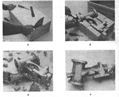
- After the last layer has been applied, the excess material is cracked and the finished part is removed;
- After that, the surface of the part is ground, polished or painted. The finished part can be covered with sealant to protect it from moisture.

The presence of additional material has both advantages and disadvantages. On the one hand, this allows you not to make special props. Due to this, the part is not deformed in the manufacturing process. However, the removal of this material is not a simple task. In addition, it is impossible to make a hollow structure with closed surfaces. Also a minus of this method is a large amount of waste remaining in a roll and removed during the cleaning process.
Due to the bonding of layers of material, different physicomechanical properties are observed depending on the height of the product. But at the same time for the product you can use sheet material of any thickness, which ensures high accuracy of the part.
Although the method is applicable to many materials, including even metals, paper lamination is the most popular.
Rapid prototyping has become an essential part of the CAD / CAM process. Rapid prototyping technology allows users to quickly
Check CAD data. The increasing use of solid modeling provides the spread of rapid prototyping technologies. The quality of materials and the accuracy of prototypes are improved. All this suggests that technologies and systems for rapid prototyping will occupy an ever-increasing place in computer-aided design. In the near future, such systems will be available to any user and will become a familiar designer tool, improving the quality of design and reducing the time it takes to release a new product.
Source: https://habr.com/ru/post/87623/
All Articles