Hard drive is dead - now it works like a clock
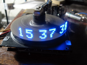
When they say that the device works “like a clock,” they mean that it means very stable and reliable. We all dream that nothing bad happened to our “hard drives”, but they like to refuse in the most unpredictable way. I redid one such disc, so now it literally works like a clock. The idea to make the device visited after visiting exhibitions, where I saw similar advertising devices. Brain drilled annoying thought - "really can not"?
')
Hard drives disassembled is not the first time. First, out of interest - and how is everything arranged there? Then, when destroying old computers, the paranoid concern for the security of the bosses demanded the indispensable use of completely intact (albeit outdated) disks. Well, attempts to make one of the two dead "screws" were also made, but often unsuccessfully. Now I had to pick a candidate for "reincarnation." He worked as an admin then, so there was plenty to choose from. I don’t even remember which disk was altered (it was 2004), it seems it was Fujitsu.
The disc was disassembled, the plates, heads and electromagnet of positioning were removed, threw out all the electronics. A bare duralumin core with a synchronous three-phase brushless DC motor ( BLDC - Brush Less Direct Current) fixed on it remained. All unnecessary ribs in duralumin cut dorm cutter.
I found two ferrite cups, wound a winding around the eye (the number of turns approximately calculated for the required output voltage) in the upper and lower cups. The top cup was fixed on the top of the stator, and the bottom one on the rotor (clearly visible in the photo) - this is how a rotating transformer, transmitting energy, came out. Transformers similar in principle of operation are located in the rotating heads of video players and video recorders (they transmit not the power, but the signal from the video heads). Of course, those transformers are much better than mine, ferrite cups there are more accurate and the gap between them is quite small. In the center hole of the cups placed the LED and the photodiode - optocoupler, through which the code will be transmitted, switching LEDs.
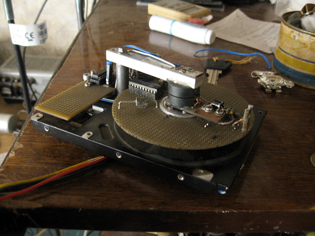
Cut out two layouts — one round — it became a rotor, another rectangular, attached it to the bottom of a dural framework of the disk — for the main control circuit. On the rotor, he mounted a simple circuitry - a current rectifier connected to the bottom cup of a rotating transformer, and a microcontroller that controls eight SMD LEDs. I assembled the control circuit - the microcontroller polls the chip of the electronic clock, forms the control phases for the rotation of the motor, and transmits the data to the top, to the display circuit (which rotates). Wrote software for microcontrollers.
Of course, everything sounds simple. But in fact, sculpted for quite a long time, despite the presence of an in-circuit emulator of microcontrollers. We had to solve quite a lot of problems - rewind the transformer, pick up current stabilization through the motor phases (if the current is weak, then the motor could not be quickly turned, and if too strong, the motor overheated and the windings closed), make the software clearly synchronous with time (sometimes they say real time code) - so that the resulting image does not tremble and the motor rotates steadily, and at the same time, the clock chip is read and the user interface is processed (the encoder and the button, through which the setup and time correction and clock menu works) nika), as well as information transmitted synchronously to the rotor assembly. And the software for the rotor unit had to be adjusted according to the principle of the flashed / checked / not_ worked out, since you will not connect the emulator to the rotating layout. Nevertheless, it was interesting to solve many problems.
Who are interested in boring technical details of the HddClock project - welcome to the microsin.ru/content/view/733/44 page. There you can download the source code and clock schemes. I saw a similar construction in harabre - http://habrahabr.ru/blogs/gadgets/86890/ .
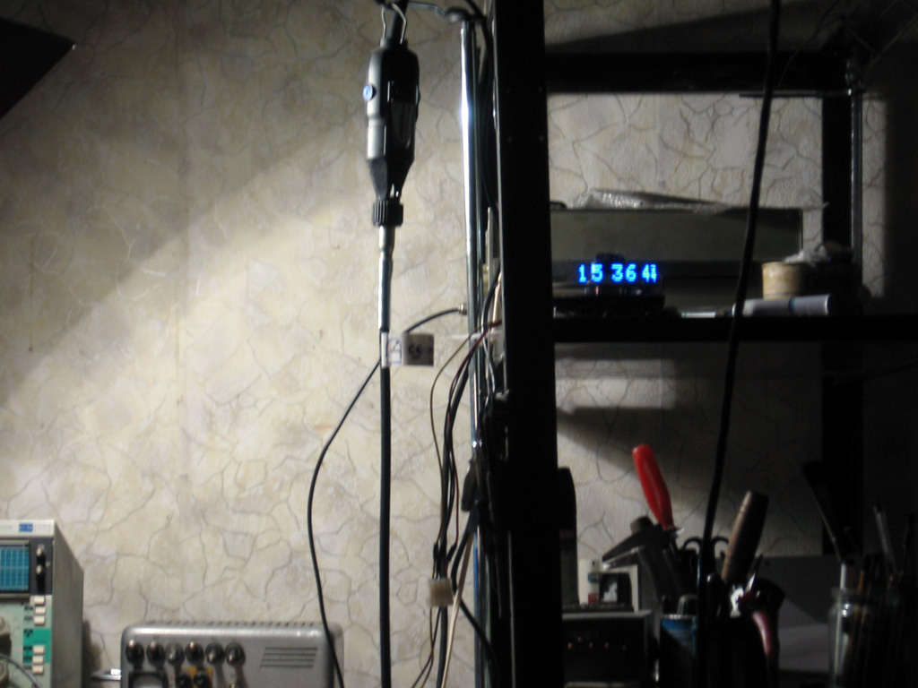
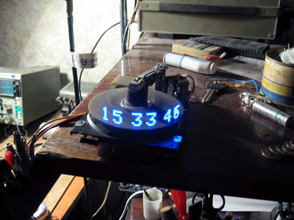
Video shot by the Canon PowerShot A520 soap box . Unfortunately, the soap dish does not make the video longer than 30 seconds, and my directorial skills did not allow me to show how the whole menu works (clock correction), how the clock starts, how the alarm clock works, etc. The quality is also not so hot (in real life look much better) - too low frame rate. The video shows the flickering numbers, which actually is not - this effect is due to the stroboscopic effect between the rotational speed and the frame rate of the video taken. The sound is also of poor quality - it is not the same as it was in the video. The LEDs are now red, changed after repair - unsuccessfully tried to turn off the alarm and hit the rotor with fingers.
UPD : updated requests for archives with photos, and posted on the site 3 additional photos with annotations (photos have labels with captions - what is where it is, what it is for and how it works).
UPD110220 : one guy with the nickname dccharacter also made a similar watch and uploaded a video on YouTube. Congratulations, colleague!
Source: https://habr.com/ru/post/87034/
All Articles