Ptolemy simulation environment
Ptolemy
Ptolemy is an environment for modeling parallel heterogeneous systems operating in real time. The project is being developed by students of the University of Berkeley under the guidance of Professor Edward Lee (Edward Lee). Java is used as the development language. Ptolemy is constantly evolving. Added support for new computing models and new demo models, expanding documentation.
Ptolemy allows you to work with a dozen different computation models, among which there is, for example, a discrete-time model (discrete-event modeling) and a state machine (finite-state machine). The modeling is based on the concepts of Actor and Director, which can be translated as "Executive Link" and "Managing Link", respectively. Director sets the calculation model in which the simulated system operates. A number of Actors, in combination with the connections between them, determine the actual structure of the system. In the first article I want to refer to the discrete-time model.
Discrete event
DE provides basic tools for simulating real-time systems, for example, queuing systems and communication networks. The simulation process is the movement of markers (token) between Actors. A marker in its essence represents some kind of data structure. When the marker gets into Actor, it will trigger some action that can change the internal state of Actor and generate new events. DE-scheduler ensures that all events occur strictly synchronously. Transferring a marker between Actors does not take time. It is important to remember that markers cannot spontaneously appear or disappear.
')
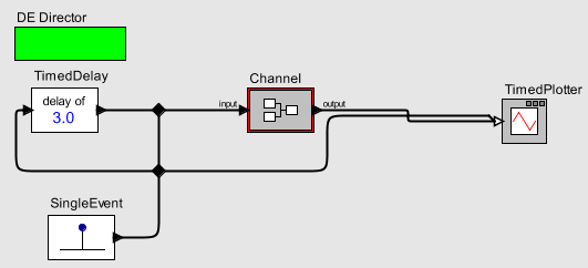
Let's assemble a simple discrete-time model. Let it be a data transmission channel in which the delay and packet loss is simulated. Packages will be markers. To begin, open the editor window ( File - New - Graph Editor ). Most of the window is occupied by the working area on which the model is to be assembled. To the left of the workspace is the library of Actors and Directors. Add a DE Director from the Directors section to the workspace. Instead of the English word Actor, which in this context is not succinctly translated into Russian, I will use the word “block”.
Since the markers cannot spontaneously appear and disappear, we will need some source. Use the SingleEvent block from the section Actors / DomainSpecific / DescreteEvents . This unit does not work slyly: it produces one marker at a specified time. The value of the marker and the time can be specified in the block settings (the parameter settings window is opened by double clicking on the block). Next we need to simulate the delay in the transmission of packets in the channel. To do this, add the Server block from the same section of the library.
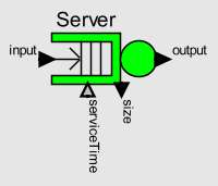 As the name suggests, this block simulates server operation in terms of a queuing system. If the marker came to a free server, then it is output on an exit with a delay equal to the value of the serviceTime parameter, and the server switches to the “busy” state for this time. If the token has arrived, and the server is busy, then it is placed in the server queue (the size of which is determined by the capacity parameter). The queue operates according to the FIFO principle; accordingly, when the server is released, the most senior marker in the queue is sent to the output with a delay of serviceTime. The server is good in that, unlike, for example, a simple Delay block determines the delay for each marker at the time of the sample from the queue (if the server was free, then the selection occurs at the time of the arrival of the marker). In simple terms, this means that the delay does not have to take into account the waiting time in the queue.
Connect the SingleEvent output to the server input.
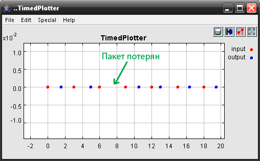
 If you run the model, then with the standard parameters of both blocks, the following will occur: at the moment of time equal to 0.0, the output marker of the SingleEvent block will appear as a boolean token with the value true, will go to the unused server, at the same time it will be delayed for a model time of 1.0. At time 1.0, the marker will exit the server. To convince this add a plotter ( Actors / Sinks / TimedSinks / TimedPlotter ). The plotter accepts double markers and displays them on a graph (time value). The white color of the input port of the plotter means that more than one line can be connected to it. On the chart, markers of different lines will be displayed in different colors.
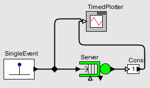 Change the marker value in SingleEvent to zero so that the plotter can display it. For clarity, let us provide the output of the server to the input of the Const block ( Actors / Sources / GenericSources ), which will generate a marker with a value of 1 at the time of arrival of any marker at the input. Exit Const served on the plotter. After launching the model, the plotter window should open.
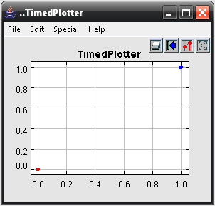 In the settings of the display format, set the appearance of the dots points. The plotter turns out to be an indispensable tool in debugging models, since it graphically displays not only the value of the marker, but also the corresponding point in time.
So far, the Server block delays any marker for a strictly defined time specified in its parameters. We introduce an element of chance. To do this, you need a Uniform block from the Actors / Random section, which, when a marker arrives at the input, generates a new marker with a random value distributed according to the normal law between the lower and upper bounds (set in parameters).
 Let's give the server output to the trigger input of the Uniform block, and its output to the serviceTime input of the Server block. Thus, a token passed through the server causes the generation of a new delay value, which is applied to the next token.
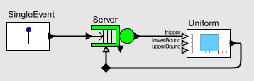
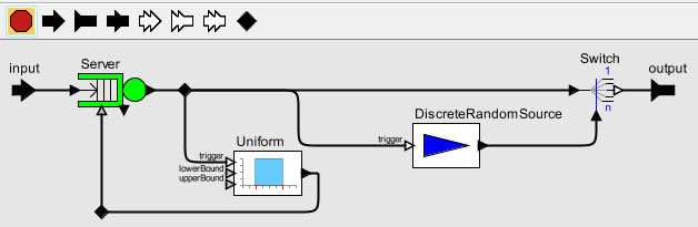
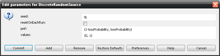
For the rough correspondence of the simulated channel to the real, all that is missing is the packet loss during transmission. To simulate losses, use the DiscreteRandomSource block from the same Random section. Its values parameter indicates the array of generated values, and the pmf (Probability mass function) parameter indicates the array of probabilities for generating each value. We specify in values the values 0 and 1, and in pmf - 0.85 and 0.15.

When a marker arrives at the trigger input, a block with a probability of 85% will generate a zero and with a probability of 15% a one. Connect the trigger input to the server output. (For branching lines, nodes are used - black rhombus on the toolbar) Use these values as a sign of loss (one - packet is lost).
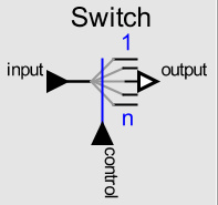 Now, when the presence of a packet loss is determined by the random images in the model, it remains to realize the loss itself. To do this, we use the Switch element (section Actors / FlowControl / Aggregators ). The packet arriving at its input is transmitted to one of the outputs, the number of which determines the value at the control input. The first line connected to the Switch has an index of 0, the next one is 1, and so on. Connect the output of the server through the node to the input of the Switch block. If we now connect a packet loss sign to its control input, and only one line to the output, then when generating the loss sign (unit at the control input), the marker will be transmitted to the line with index 1, and for the line with index 0, which is our continuation channel, it will be "lost."
Such a simple channel in itself is of small interest, but it is convenient to use it for modeling network protocols. A simulated channel can transmit packets with a random delay and lose them with a certain probability.
Ptolemy allows you to create new Actor'y, collecting them from existing ones. In the Utilities section of the library is a CompositeActor block, in which you can place any other blocks, including the CompositeActor. Place the channel model in the CompositeActor. The CompositeActor workspace is opened with the OpenActor command from the context menu. The SingleEvent block is no longer needed. Instead, add one input and one output port.
You can simplify the work with the channel, if you "bring out" all the important parameters: the lower and upper limits of the range of time delays and the probability of packet loss. To do this, we will add lowDelayBorder, highDelayBorder and lossProbability parameters in the block parameter settings window. The Add button brings up the corresponding dialog, in which, in particular, you can specify default values for the added parameters. The names of the new parameters are now available inside the block. Replace specific values with parameter names in the Uniform and DiscreteRandomsource blocks.
Gathering a primitive package source:
You can test the channel:
In the settings of the DE Director there is an important parameter - stopTime. By default, it is set to infinity, but to observe such a simple model, a value of 50 will suffice.
On this let me finish the acquaintance with Ptolemy. If the topic turns out to be in demand, then a sequel will soon follow.
Source: https://habr.com/ru/post/87007/
All Articles