Power Transmission by Single Wire
For electricians, the ability to transmit electrical energy over a single wire should be known. This is not a miracle. However, for professionals this opportunity may seem rather fantastic, or at least unusual. In this article I would like to share my own experience in this area. I strongly recommend, before reading this article, to get acquainted with the original information from the works of N.Tesla. About single-wire transmission of energy (hereinafter OPE) is known from the 19th century. The following conditions are necessary for the implementation of the OPE: the current should be variable and relatively high-frequency, as well as a sufficiently high voltage. For example: current frequency 10-15kHz, voltage 10-15kV. Although the experiments are easier to carry out with less voltage, I used 100-200V. To increase the efficiency of the process, it is necessary to use resonance.

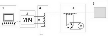
My scheme of OPE is as follows: 1 - a laptop; 2 - ULF, 3 - step-up transformer (laptop, ULF and step-up transformer play the role of a current generator of the nature I need, ie, high-frequency and high-voltage); 4 - load in the form of a step-down transformer and a diode bridge on a low-voltage winding, with a DC motor connected to it; 5 - insulated conductive plate.
Now take a closer look at the details of the scheme. In fact, this scheme has two nuances.
The first is a step-up transformer, pay attention to the wiring diagram. One end of the secondary winding is connected to one of the primary terminals, and, preferably, is grounded. This is done to ensure safety, as well as to improve the efficiency of the secondary winding. Further, a capacitor is connected in parallel to the primary winding, forming a parallel oscillating circuit. The capacitance of a capacitor is calculated using known formulas, depending on the inductance of the primary winding and the frequency used. This is done to increase the current in the primary winding, and, accordingly, to enhance the effect. The selection of the capacitor capacitance may cause a problem, since the inductance of the primary winding during its operation is less than in the disconnected state, and this difference depends on the load on the secondary winding. I solved this question simply: I calculated the capacitor for inductance less by 10% -15% of the measured value, at a given frequency. And even after that, it was necessary to adjust the frequency of the generator a little, in order to adjust the maximum resonance.
')
The second nuance is to adjust the resonance in the secondary circuit. The inductance of the secondary circuit consists of the inductance of the secondary winding of the step-up transformer and the primary winding of the step-down transformer. The inductance of the primary winding of a step-down transformer will also be slightly less measured, since it depends on the load on the secondary winding. Next, you need to choose the capacity of the conductive insulated plate. This is done simply by measuring the area of the plate and using the formulas we calculate the capacitance for a given frequency and inductance. The plate must be placed at a distance from the surrounding objects, otherwise its capacity will be larger than the calculated one. The higher the frequency and the greater the inductance of the circuit, the less capacitance is required, and hence the area of the plate. At a sufficiently high frequency, the own capacitance of the chain may suffice, in which case the plate is not needed. My test bench allowed the motor to operate at a power of 10W at full power, light incandescent lamps, and, of course, blown fluorescent lamps. In my opinion, OPE has two main advantages. The first - consumes less materials on the conductors. The second is due to the increased frequency and high voltage through the conductor, a relatively small current flows, the wire is almost not heated, which favorably affects the resistance. Having studied this material, I really hope that you have a question: “And what, in this case, prevents us from using the Earth as a conductor?”. My answer is nothing! And it is possible and much simpler:
The video presents a very primitive scheme, with the help of which the transfer of electricity through a single wire is demonstrated. In fact, to transfer electricity through a single wire at the moment does not make practical sense, in my opinion. This information is posted here only to show the possibility of transmitting energy and signals through the Earth.
PS The article is written by Roma,who has long wanted to get on Habr, but now, I think, he will succeed in it, which fell on Habr thanks to an invite from Veider . While I do not know the name of Roman, but as soon as I find out, I will definitely place it here.
PS 2 This is the second person who participates in my experiment on “selling” invites. The essence of the experiment is that I sell an invite for an article. I think that people who write articles are worthy of becoming users. Not to give invites just because I decided after two invited people who, after already a year of being at the Habré, did nothing. I think you will understand me. Thank.
PS 3 Since the author was not able to fully convey the idea - I will tell. In this case, the capacitive energy works. Here we get an oscillating circuit at the expense of capacity and a large frequency. The EMF is induced in the secondary winding of the transformer, due to this we get the energy output from the other side of the wire.

My scheme of OPE is as follows: 1 - a laptop; 2 - ULF, 3 - step-up transformer (laptop, ULF and step-up transformer play the role of a current generator of the nature I need, ie, high-frequency and high-voltage); 4 - load in the form of a step-down transformer and a diode bridge on a low-voltage winding, with a DC motor connected to it; 5 - insulated conductive plate.
Now take a closer look at the details of the scheme. In fact, this scheme has two nuances.
The first is a step-up transformer, pay attention to the wiring diagram. One end of the secondary winding is connected to one of the primary terminals, and, preferably, is grounded. This is done to ensure safety, as well as to improve the efficiency of the secondary winding. Further, a capacitor is connected in parallel to the primary winding, forming a parallel oscillating circuit. The capacitance of a capacitor is calculated using known formulas, depending on the inductance of the primary winding and the frequency used. This is done to increase the current in the primary winding, and, accordingly, to enhance the effect. The selection of the capacitor capacitance may cause a problem, since the inductance of the primary winding during its operation is less than in the disconnected state, and this difference depends on the load on the secondary winding. I solved this question simply: I calculated the capacitor for inductance less by 10% -15% of the measured value, at a given frequency. And even after that, it was necessary to adjust the frequency of the generator a little, in order to adjust the maximum resonance.
')
The second nuance is to adjust the resonance in the secondary circuit. The inductance of the secondary circuit consists of the inductance of the secondary winding of the step-up transformer and the primary winding of the step-down transformer. The inductance of the primary winding of a step-down transformer will also be slightly less measured, since it depends on the load on the secondary winding. Next, you need to choose the capacity of the conductive insulated plate. This is done simply by measuring the area of the plate and using the formulas we calculate the capacitance for a given frequency and inductance. The plate must be placed at a distance from the surrounding objects, otherwise its capacity will be larger than the calculated one. The higher the frequency and the greater the inductance of the circuit, the less capacitance is required, and hence the area of the plate. At a sufficiently high frequency, the own capacitance of the chain may suffice, in which case the plate is not needed. My test bench allowed the motor to operate at a power of 10W at full power, light incandescent lamps, and, of course, blown fluorescent lamps. In my opinion, OPE has two main advantages. The first - consumes less materials on the conductors. The second is due to the increased frequency and high voltage through the conductor, a relatively small current flows, the wire is almost not heated, which favorably affects the resistance. Having studied this material, I really hope that you have a question: “And what, in this case, prevents us from using the Earth as a conductor?”. My answer is nothing! And it is possible and much simpler:
The video presents a very primitive scheme, with the help of which the transfer of electricity through a single wire is demonstrated. In fact, to transfer electricity through a single wire at the moment does not make practical sense, in my opinion. This information is posted here only to show the possibility of transmitting energy and signals through the Earth.
PS The article is written by Roma,
PS 2 This is the second person who participates in my experiment on “selling” invites. The essence of the experiment is that I sell an invite for an article. I think that people who write articles are worthy of becoming users. Not to give invites just because I decided after two invited people who, after already a year of being at the Habré, did nothing. I think you will understand me. Thank.
PS 3 Since the author was not able to fully convey the idea - I will tell. In this case, the capacitive energy works. Here we get an oscillating circuit at the expense of capacity and a large frequency. The EMF is induced in the secondary winding of the transformer, due to this we get the energy output from the other side of the wire.
Source: https://habr.com/ru/post/81513/
All Articles