Programming in tables is a new concept of recording conditional (and not only) constructions.
Not so long ago, while searching online for alternative programming approaches, I came across a very interesting video . This is a 40-minute presentation with the intriguing title “No Ifs, Ands, or Buts. Uncovering the Simplicity of Conditionals . Presenter Jonathan Edwards ( Jonathan Edwards ) talks about the new concept of writing conditional constructs using the schematic tables he created.
This topic should be interesting to anyone who is at least a little interested in programming. If you do not have at your disposal forty minutes, or you cannot watch the video for any other reason, I suggest that you familiarize yourself with my brief retelling of the presentation of Jonathan.
The author of the original idea with simple examples shows us the key features of the schematic tables and compares them with the traditional writing of conditional constructions in the C language (in fact, Java, but the examples mainly use its C-subset). In addition to the video, there is also an article on this topic, where the concept is described in a more formal language. Since this retelling is aimed at briefing you about the most interesting moments of the presentation, I omitted some mathematical details with which the author operates, and focused on examples and comparisons.
Let us first consider the structure of a schematic table using the example of the function
')

The first column records variables. In this example, we have only two of them - the input parameter
Thus, the columns are responsible for the conditions. The rows of the table, in turn, are responsible for the actions. They contain functions that are performed sequentially one after the other, starting from the top and moving down. Let's write down the sequence of actions defined in the schematic table of the function

As can be seen from the figure, the number 3 was passed as the input parameter of the function, and it returned to us 2. The entry in the
The ability to view all intermediate values is one of the remarkable features of schematic tables. Jonathan claims to have borrowed this idea from spread sheets , in which all values are calculated on the fly. If you click on the blue arrow, over which the cursor is located in the figure above, another table appears, corresponding to the recursive call of the function

Such an opportunity can potentially make the debugging process a pleasant experience.
So, on a simple example, we considered the main features of a schematic table. Now we will look at an example more difficult, which will show us one of the undoubted advantages of schematic tables.
Let's try to present a switch condition using a schematic table. Suppose we are writing a game in which there is a method for calculating the damage caused. Let's call it
Method Source Code:

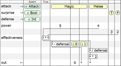
Consider those elements of the table that we have not yet met. First, there are several incoming parameters, each of which belongs to it has a certain type. Secondly, after column
So, moving from top to bottom and thinking from left to right, we come to the following sequence of actions:
Horizontal lines represent data flows between the conditions defined in the table. Thus, the presence of a horizontal line always indicates the use of data calculated in one condition (or unconditionally) in calculations with another condition.
A visual comparison of the source code of the

The size of the structure on the screen is compared on the left in two different ways of recording, and the interlacing of the logic of the method is clearly shown on the right. Since there is only one dimension in the text record of the program logic, in our example there is a “cork” - the green part in the middle is placed between two conditional blocks. This makes it harder to perceive the code, for example, if we want to know the result of the execution when the condition

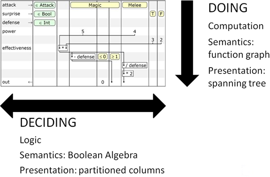
Decision making is carried out on the horizontal axis of the table. The semantics of Boolean algebra are used to write the conditions.
On the vertical axis , actions are performed that are written in the form of a graph of functions interconnected by means of input parameters and return values.
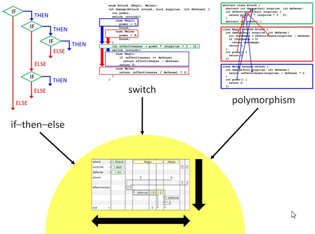
If you are still skeptical about the concept of schematic tables, I suggest you look at the following figure.

It turns out that such types of conditional constructions as nested if-then-else conditions, switch expressions, and even polymorphism (not considered here) are all reduced to a single form when using schematic tables. In my opinion, this is a good sign. Here it would be appropriate to quote Albert Einstein:
In this article I did not consider polymorphism, since it does not make major changes in the structure of the table. An example of how to replace the overriding method in Java with a schematic table begins with a presentation video from the 29th minute.
The concept described is one of several interesting features underlying the Coherence programming language developed by Jonathan. Screenshots in the article were made from the presentation video. The author has developed a shell that provides tools for interactive work with schematic tables, editing and executing them, as well as writing unit tests. You can see all this in action on video. The author also posted the source code for the shell (written in C #) along with the executable file for Windows. [ download ]
Additional material on the topic, including an article with a formal description of the concept of schematic tables, can be found at www.subtextual.org . The author also has a blog . Although it is rarely updated, you can find a description and other interesting ideas, such as, for example, co-actions .
To better understand Jonathan's ideology, one can familiarize himself with his rather radical manifesto , in which he argues against the currently accepted recording of program logic in the form of source code and suggests new ways of programming development.
Thank you for attention.
UPD:
In the comments, people express doubts about the advisability of using schematic tables in practice. I'll try to clarify the situation a little.
This method of recording program logic is by no means positioned as a complete development, for which it remains only to write an IDE with a compiler and put it to the masses. At the moment this is only a concept. In my opinion, it gives some thoughts about the current state of affairs in the field of programming. I decided that the Chabras community would be interested to learn about it, because recently we can only observe the emergence of new languages in the field, which are based on existing programming paradigms, despite the fact that they include mechanisms for simpler organization of parallel computing.
UPD2:
I apologize for the misinformation. Shell sources written in C # and the executable file for Windows can be downloaded from the project site, see the first question in the FAQ section. Subtext is its old name, now the project is named Coherence .
PS If you have comments on the style of presentation or design of the article, do not hesitate to write them in the comments or me personally. I will be glad to any criticism.
This topic should be interesting to anyone who is at least a little interested in programming. If you do not have at your disposal forty minutes, or you cannot watch the video for any other reason, I suggest that you familiarize yourself with my brief retelling of the presentation of Jonathan.
Foreword
The author of the original idea with simple examples shows us the key features of the schematic tables and compares them with the traditional writing of conditional constructions in the C language (in fact, Java, but the examples mainly use its C-subset). In addition to the video, there is also an article on this topic, where the concept is described in a more formal language. Since this retelling is aimed at briefing you about the most interesting moments of the presentation, I omitted some mathematical details with which the author operates, and focused on examples and comparisons.
Schematic tables
Let us first consider the structure of a schematic table using the example of the function
fib . It takes as input one parameter n and returns a number from the Fibonacci sequence , the sequence number of which is equal to the value n . Function source code:int fib( int n) {
assert(n >= 0);
if (n == 0) return 0;
if (n == 1) return 1;
return fib(n - 1)
+ fib(n - 2)
}
* This source code was highlighted with Source Code Highlighter .')

The first column records variables. In this example, we have only two of them - the input parameter
in and the return value out . The second column contains statements ( Assert ). Here it is used to check the non-negativity of the input parameter. All subsequent columns record conditions. The first column after the Assert is considered true when in == 0 , the second - when n == 1 , and the third - with n >= 2 .Thus, the columns are responsible for the conditions. The rows of the table, in turn, are responsible for the actions. They contain functions that are performed sequentially one after the other, starting from the top and moving down. Let's write down the sequence of actions defined in the schematic table of the function
fib :- If
in < 0, report an error (standard behavior if the condition in theAssertcolumn is not met) and terminate. - If
in == 0, return 0. - If
in == 1, return 1. - If
in >= 2, go to the next item. - Pass the result of the expression
in - 1as an input parameter to the recursive call tofib. - Transfer the result of the expression
in - 2to the second recursive function call. - Return the result of the addition of the values obtained from both recursive calls.
Assert column, which should be executed, and in the next Assert column, you need to record an unconditional call to the function being checked, passing it the values of interest to us. The result of the function will be displayed in the column "=". In our case, the test is called fib test .
As can be seen from the figure, the number 3 was passed as the input parameter of the function, and it returned to us 2. The entry in the
Assert column means that the result of the function should not be an error. Notice that the table on the right is the same schematic table that we created for the fib function, only now another column with the name “=” has been added to it, in which for each row is written the result of the operation performed in this row. In addition, columns filled with gray are not filled. In this case, the condition of the last column is satisfied ( 3 >= 2 ), and we get the result of adding the values obtained from the two recursive calls to the function fib .The ability to view all intermediate values is one of the remarkable features of schematic tables. Jonathan claims to have borrowed this idea from spread sheets , in which all values are calculated on the fly. If you click on the blue arrow, over which the cursor is located in the figure above, another table appears, corresponding to the recursive call of the function
fib . This process can be continued further. In each following table we see which column is true in the current call and the values of the operations performed in each row of the table.
Such an opportunity can potentially make the debugging process a pleasant experience.
So, on a simple example, we considered the main features of a schematic table. Now we will look at an example more difficult, which will show us one of the undoubted advantages of schematic tables.
Switches (switch-statements)
Let's try to present a switch condition using a schematic table. Suppose we are writing a game in which there is a method for calculating the damage caused. Let's call it
damage . Based on the type of attack, its surprise and the level of protection of the attacker, the method returns a certain damage value.Method Source Code:
enum Attack {Magic, Melee};

int damage(Attack attack, bool surprise, int defense) {
int power;

switch (attack) {
case Magic:
power = 5;
break ;

case Melee:
power = 4;
break ;
}

int effectiveness = power * (surprise ? 3 : 2);

switch (attack) {
case Magic:
if (effectiveness >= defense)
return effectiveness - defense;
return 0;

case Melee:
return (effectiveness / defense) * 2;
}
}

* This source code was highlighted with Source Code Highlighter .
Consider those elements of the table that we have not yet met. First, there are several incoming parameters, each of which belongs to it has a certain type. Secondly, after column
Assert new column True . It contains unconditional actions that are always performed. Thirdly, in the first column, in addition to the input parameters and the return value, another type of variables appeared - local variables. Strictly speaking, each row without a name is an anonymous local variable (this is clearly demonstrated in the unit test tables, which was reviewed earlier). But in some cases it is convenient to give the string some name so that later it can be used in subsequent operations and functions.So, moving from top to bottom and thinking from left to right, we come to the following sequence of actions:
- Based on the type of attack, assign the value 5 or 4 to the local
powervariable. - Based on the sign of a surprise attack, assign the value 3 or 2 to an anonymous local variable.
- Assign the local variable of
effectivenessresult of the product of two variables, the values of which were defined in paragraphs 1 and 2. - If
attack == Magic, Subtract the value of thedefensevariable from theeffectiveness. - If
attack == Magic & defense <= 0, return the value 0. - If
attack == Magic & defense >= 1, return the result of the subtraction ofeffectiveness - defense. - If
attack == Melee, return the result of the expression ofeffectiveness / defense * 2.
True column (item 3) is performed always when the queue reaches it — it does not depend on the fulfillment of one or another condition. All other operations are selected from a column whose condition is true for the current set of input parameters.Horizontal lines represent data flows between the conditions defined in the table. Thus, the presence of a horizontal line always indicates the use of data calculated in one condition (or unconditionally) in calculations with another condition.
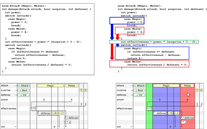
A visual comparison of the source code of the
damage method and the corresponding schematic table with the same font size:
The size of the structure on the screen is compared on the left in two different ways of recording, and the interlacing of the logic of the method is clearly shown on the right. Since there is only one dimension in the text record of the program logic, in our example there is a “cork” - the green part in the middle is placed between two conditional blocks. This makes it harder to perceive the code, for example, if we want to know the result of the execution when the condition
attack == Magic is met. In the case of a schematic table, logic and actions are located on two different axes orthogonal to each other. And here we come to the fundamental principle of the concept of schematic tables - the representation of code in two dimensions, instead of one.
Decision making is carried out on the horizontal axis of the table. The semantics of Boolean algebra are used to write the conditions.
On the vertical axis , actions are performed that are written in the form of a graph of functions interconnected by means of input parameters and return values.
If you are still skeptical about the concept of schematic tables, I suggest you look at the following figure.

It turns out that such types of conditional constructions as nested if-then-else conditions, switch expressions, and even polymorphism (not considered here) are all reduced to a single form when using schematic tables. In my opinion, this is a good sign. Here it would be appropriate to quote Albert Einstein:
Everything should be as simple as possible, but not simpler.
In this article I did not consider polymorphism, since it does not make major changes in the structure of the table. An example of how to replace the overriding method in Java with a schematic table begins with a presentation video from the 29th minute.
Conclusion
The concept described is one of several interesting features underlying the Coherence programming language developed by Jonathan. Screenshots in the article were made from the presentation video. The author has developed a shell that provides tools for interactive work with schematic tables, editing and executing them, as well as writing unit tests. You can see all this in action on video. The author also posted the source code for the shell (written in C #) along with the executable file for Windows. [ download ]
Additional material on the topic, including an article with a formal description of the concept of schematic tables, can be found at www.subtextual.org . The author also has a blog . Although it is rarely updated, you can find a description and other interesting ideas, such as, for example, co-actions .
To better understand Jonathan's ideology, one can familiarize himself with his rather radical manifesto , in which he argues against the currently accepted recording of program logic in the form of source code and suggests new ways of programming development.
Thank you for attention.
UPD:
In the comments, people express doubts about the advisability of using schematic tables in practice. I'll try to clarify the situation a little.
This method of recording program logic is by no means positioned as a complete development, for which it remains only to write an IDE with a compiler and put it to the masses. At the moment this is only a concept. In my opinion, it gives some thoughts about the current state of affairs in the field of programming. I decided that the Chabras community would be interested to learn about it, because recently we can only observe the emergence of new languages in the field, which are based on existing programming paradigms, despite the fact that they include mechanisms for simpler organization of parallel computing.
UPD2:
I apologize for the misinformation. Shell sources written in C # and the executable file for Windows can be downloaded from the project site, see the first question in the FAQ section. Subtext is its old name, now the project is named Coherence .
PS If you have comments on the style of presentation or design of the article, do not hesitate to write them in the comments or me personally. I will be glad to any criticism.
Source: https://habr.com/ru/post/80893/
All Articles