WiMAX Base Station
WiMAX Base Station.
Past his article “WiMAX. How it works ” I dedicated to the description of the technology, general words about the mechanisms used, and showed the approximate structure of the network. Since this topic is interesting to the community, I continue.
This time you will come close to the WiMAX Base Station, find out how it works and be able to ask questions that interest you.
In essence, a WiMAX network is an ordinary IP network, on one of the segments of which radio waves are used as the transmission medium. On the other hand, on the physical layer, WiMAX is very similar to GSM, CDMA and any other wireless networks.
Under the cat you can learn about the elements of the BS, the principle of operation and the mechanisms used.
Habrakat is a wonderful thing; it helps to separate the wheat from the chaff for each specific article. However, I digress, sorry.
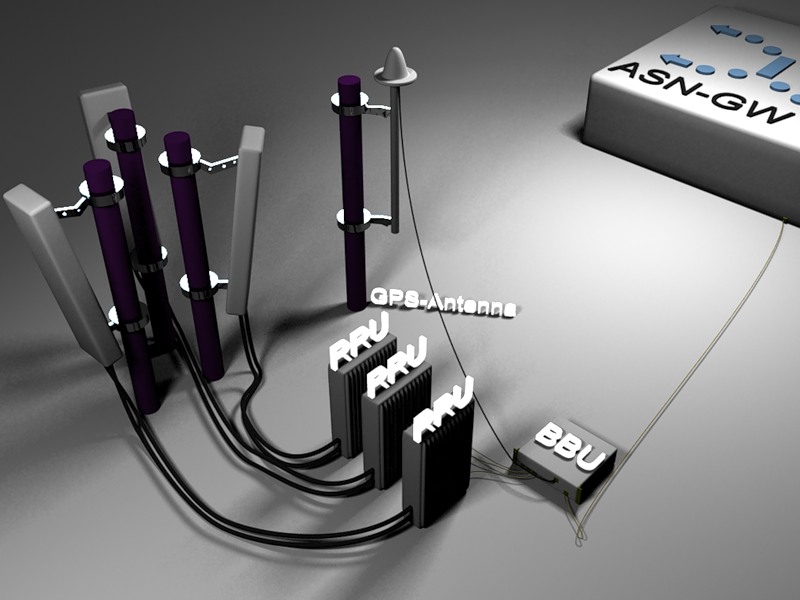
The BS scheme is not fundamentally different from that used in other wireless technologies: the main internal module, amplifiers and antennas. The only difference is the presence (sorry for the pun) the GPS antenna.
')
Before the beginning of the story, I want to say that we will talk about the implementation of Huawei, so some points may be specific to this company.
So. The base station DBS3900 (Distributed Base Station) consists of an internal processing node (BBU in Huawei terminology), amplifiers (RRU) and antennas.
Of course, the “brain” of the BS is the BBU - BaseBand Unit. Almost all the data processing, synchronization, control, and statistics collection falls on this node.
Physical layer PDUs arrive at the BBU from the ASN side. The data of the data link layer are processed using various coding schemes, modulations corresponding to the signal level, undergo the inverse Fourier transform, Cycle Prefix is added to them and then sent to the amplifier.
DMS39000 consists of the following boards.
The first 4 slots (from 0 to 3) are reserved for BBBI (BWA BaseBand processing and radio Interface unit) boards. Each board has three optical interfaces (CPRI-Common Public Radio Interface) for connecting amplifiers. One or two cards can be installed, each of which occupies two slots.
Slots 4 and 5 are reserved for the Universal Satellite card and Clock Unit. This board also takes up two slots and is used for synchronization. For WiMAX using time duplex (TDD) synchronization is a very important issue, since the time of reception / transmission must be synchronized for different sectors of the same base station and for other base stations that are neighboring for the considered one. Generally speaking, GPS is used as the easiest and most versatile method. But, as I said somewhere in the comments to other articles, in Russia they oblige to install, in addition to GPS, the GLONASS receiver board - K161, for which the manufacturer has provided the USCU legs and a small jumper. The main connector on this board is SMA for sales from the GPS antenna.
The sixth and seventh slot is used for the “main” BBU board - BMPT (BWA Main Processing & Transmission unit). Actually, this is the BS BSU, it controls all the processes. It has an Ethernet port for management, two RG-45 FE / GE ports, and two LC optical ports for communication with the ASN network (only two ports can be logically configured). In addition, a logical interface is configured on it to communicate with the control network.
Two more boards are located on the right side of the front panel - UPEU (Universal Power and Environment Interface Unit), which operate in Hot Standby mode. They are located switch, power connector, dry contacts and connectors for connecting external monitoring units (RJ-45).
What happens next with the data processed by the BBU? Optical interfaces connected to CPRI ports transmit data to an amplifier unit (RRU - Radio Remote Unit). Digital-analog (analog-digital) conversions, radiation power control, imposition of an analog signal on a high-frequency signal and multiplexing of receive and transmit signals occur on the amplifier.
Next, the signal is transmitted to the antenna by the feeder. For the implementation of MIMO in each antenna, essentially two antennas are installed, having cross-polarization to reduce interference. The antennas themselves are just tiny, if we compare them with GSM. This is naturally related to the frequencies used.
DBS3900 supports up to 1024 subscribers per sector (both active users and those who are in IDLE mode are considered). More than 3,000 subscribers can be “planted” on the base station in this way. Unfortunately, I cannot say how realistic this is - such values have not yet been achieved.
When using a bandwidth of 10 MHz on a downlink, you can get 30 Mbps per sector (at 5 MHz - 15 Mbps). This is possible if you tune in the MIMO 2T2R SM BS (two antennas to receive, two to transmit, transmitting and receiving various information), PUSC with All SC (this will be discussed later) and the ratio of the daunlik to the uplink 32:15 (we are talking about the ratio of the number of OFDMA symbols in the frame allocated for DL / UL, respectively). Under the same conditions on the uplink you will have 6 Mbit / s per sector.
Now you can dwell on various specific things.
Signal quality is determined by two main parameters: RSSI and CINR.
RSSI = Recieve Signal Strength Indicator. Measured in dBm and mean signal level. The farther from the BS, the lower this value. Any obstacles aggravate it: buildings, trees.
CINR = Carrier to Interference and Noise Ratio. An objective measure of the quality of the received signal, measured in dB. The lower the value, the worse the signal. This may be due to either distance from the BS or interference.
These two parameters are defined both for the downlink (sometimes reflected on the subscriber devices) and for the uplink (you can only request this information from the BS equipment). The RSSI on uplink can be much lower due to the weak transmitting antennas of mobile devices, but this is compensated for by the powerful BS receiving antennas.
What is MIMO? Technology with this modest name allows you to use multiple antennas for reception and transmission. What can it be needed for? There are two possible answers to this account and two corresponding implementations:
MIMO Matrix A (Diversity mode): the same data is transmitted through different antennas. This scheme is used to improve the quality of the transmitted signal and improve reception.
MIMO Matrix B (Spatial Multiplexing (SM) mode): Various data is transmitted through various antennas. This allows you to increase the speed of data transmission.
Currently, Huawei is testing MIMO 4T4R in the United States.
The data transfer rate for each specific device is determined, roughly speaking, by the modulation used, the coding scheme and the Repetition parameter. Repetition means the number of retransmissions (2, 4, 6) with a bad signal. All these parameters are selected automatically, for which the AMC (Adaptive Modulation and Coding) mechanism is responsible
In the comments to the previous topic, I was asked to touch on the topic of "breathing cell".
Breathing cell is called the ability of the BS to change its power, and hence the coverage area, in accordance with the load on the BS and the neighboring ones. The number of subscribers and the traffic consumed are taken into account. It turns out that the range of a lonely standing BS will be much larger than that of a BS, near which there are neighboring ones, in equal conditions. This is in theory. In practice, unfortunately, this was not the case.
One of the serious advantages of WiMAX is the possibility of using an adaptive antenna system that adjusts its radiation pattern in accordance with the movement of the subscriber station, that is, as if it grabs it and monitors it. But the rationality of its use is another question. It will most likely work fine in rural areas with low buildings and few subscribers. How it will work in urban environments, I do not presume to suggest.
Now, what is PUSC with all sub-channels, and also PUSC 1/3 sub-channels and FFR.
This is about reuse of frequencies.
PUSC = Partially Usage of Sub-Channels. PUSC 1/3 uses one single frequency on all BSs. Each sector uses 1/3 of all subchannels (hence the name. A little more detail can be found, for example, here ).
PUSC with all sub-channels (aka FUSC - Full Usage of Sub-Channels) uses all sub-channels for one sector. That is, for one BS you need three different frequencies.
FFR (Fractional Frequency Re-Use) - roughly speaking, smart PUSC 1/3. All BSs use the same frequency. But at the same time, in the area of confident coverage of a particular sector, PUSC with all sub-channels is used, and at the borders of PUSC sectors, 1/3. This allows subscribers located near the BS to maximize the capabilities of the network.
So now you know that if you only have permission for one frequency, you can use PUSC 1/3 or FFR. Of course, if the equipment supports FFR, then it is better to use it. And if you have at least three frequencies, then it is better to use PUSC with all sub-channels.
<In this article, I did not go into details, so as not to produce entities beyond necessity (comprehensive information on most issues can be found in Wikipedia), but only touched their meaning and value for us - users>
Past his article “WiMAX. How it works ” I dedicated to the description of the technology, general words about the mechanisms used, and showed the approximate structure of the network. Since this topic is interesting to the community, I continue.
This time you will come close to the WiMAX Base Station, find out how it works and be able to ask questions that interest you.
In essence, a WiMAX network is an ordinary IP network, on one of the segments of which radio waves are used as the transmission medium. On the other hand, on the physical layer, WiMAX is very similar to GSM, CDMA and any other wireless networks.
Under the cat you can learn about the elements of the BS, the principle of operation and the mechanisms used.
Habrakat is a wonderful thing; it helps to separate the wheat from the chaff for each specific article. However, I digress, sorry.
Scheme
The BS scheme is not fundamentally different from that used in other wireless technologies: the main internal module, amplifiers and antennas. The only difference is the presence (sorry for the pun) the GPS antenna.
')
DBS3900
Before the beginning of the story, I want to say that we will talk about the implementation of Huawei, so some points may be specific to this company.
So. The base station DBS3900 (Distributed Base Station) consists of an internal processing node (BBU in Huawei terminology), amplifiers (RRU) and antennas.
Of course, the “brain” of the BS is the BBU - BaseBand Unit. Almost all the data processing, synchronization, control, and statistics collection falls on this node.
Physical layer PDUs arrive at the BBU from the ASN side. The data of the data link layer are processed using various coding schemes, modulations corresponding to the signal level, undergo the inverse Fourier transform, Cycle Prefix is added to them and then sent to the amplifier.
DMS39000 consists of the following boards.
The first 4 slots (from 0 to 3) are reserved for BBBI (BWA BaseBand processing and radio Interface unit) boards. Each board has three optical interfaces (CPRI-Common Public Radio Interface) for connecting amplifiers. One or two cards can be installed, each of which occupies two slots.
Slots 4 and 5 are reserved for the Universal Satellite card and Clock Unit. This board also takes up two slots and is used for synchronization. For WiMAX using time duplex (TDD) synchronization is a very important issue, since the time of reception / transmission must be synchronized for different sectors of the same base station and for other base stations that are neighboring for the considered one. Generally speaking, GPS is used as the easiest and most versatile method. But, as I said somewhere in the comments to other articles, in Russia they oblige to install, in addition to GPS, the GLONASS receiver board - K161, for which the manufacturer has provided the USCU legs and a small jumper. The main connector on this board is SMA for sales from the GPS antenna.
The sixth and seventh slot is used for the “main” BBU board - BMPT (BWA Main Processing & Transmission unit). Actually, this is the BS BSU, it controls all the processes. It has an Ethernet port for management, two RG-45 FE / GE ports, and two LC optical ports for communication with the ASN network (only two ports can be logically configured). In addition, a logical interface is configured on it to communicate with the control network.
Two more boards are located on the right side of the front panel - UPEU (Universal Power and Environment Interface Unit), which operate in Hot Standby mode. They are located switch, power connector, dry contacts and connectors for connecting external monitoring units (RJ-45).
Amplifier
What happens next with the data processed by the BBU? Optical interfaces connected to CPRI ports transmit data to an amplifier unit (RRU - Radio Remote Unit). Digital-analog (analog-digital) conversions, radiation power control, imposition of an analog signal on a high-frequency signal and multiplexing of receive and transmit signals occur on the amplifier.
Antennas
Next, the signal is transmitted to the antenna by the feeder. For the implementation of MIMO in each antenna, essentially two antennas are installed, having cross-polarization to reduce interference. The antennas themselves are just tiny, if we compare them with GSM. This is naturally related to the frequencies used.
Technical Details
DBS3900 supports up to 1024 subscribers per sector (both active users and those who are in IDLE mode are considered). More than 3,000 subscribers can be “planted” on the base station in this way. Unfortunately, I cannot say how realistic this is - such values have not yet been achieved.
When using a bandwidth of 10 MHz on a downlink, you can get 30 Mbps per sector (at 5 MHz - 15 Mbps). This is possible if you tune in the MIMO 2T2R SM BS (two antennas to receive, two to transmit, transmitting and receiving various information), PUSC with All SC (this will be discussed later) and the ratio of the daunlik to the uplink 32:15 (we are talking about the ratio of the number of OFDMA symbols in the frame allocated for DL / UL, respectively). Under the same conditions on the uplink you will have 6 Mbit / s per sector.
Now you can dwell on various specific things.
Signal quality is determined by two main parameters: RSSI and CINR.
RSSI = Recieve Signal Strength Indicator. Measured in dBm and mean signal level. The farther from the BS, the lower this value. Any obstacles aggravate it: buildings, trees.
CINR = Carrier to Interference and Noise Ratio. An objective measure of the quality of the received signal, measured in dB. The lower the value, the worse the signal. This may be due to either distance from the BS or interference.
These two parameters are defined both for the downlink (sometimes reflected on the subscriber devices) and for the uplink (you can only request this information from the BS equipment). The RSSI on uplink can be much lower due to the weak transmitting antennas of mobile devices, but this is compensated for by the powerful BS receiving antennas.
What is MIMO? Technology with this modest name allows you to use multiple antennas for reception and transmission. What can it be needed for? There are two possible answers to this account and two corresponding implementations:
MIMO Matrix A (Diversity mode): the same data is transmitted through different antennas. This scheme is used to improve the quality of the transmitted signal and improve reception.
MIMO Matrix B (Spatial Multiplexing (SM) mode): Various data is transmitted through various antennas. This allows you to increase the speed of data transmission.
Currently, Huawei is testing MIMO 4T4R in the United States.
The data transfer rate for each specific device is determined, roughly speaking, by the modulation used, the coding scheme and the Repetition parameter. Repetition means the number of retransmissions (2, 4, 6) with a bad signal. All these parameters are selected automatically, for which the AMC (Adaptive Modulation and Coding) mechanism is responsible
In the comments to the previous topic, I was asked to touch on the topic of "breathing cell".
Breathing cell is called the ability of the BS to change its power, and hence the coverage area, in accordance with the load on the BS and the neighboring ones. The number of subscribers and the traffic consumed are taken into account. It turns out that the range of a lonely standing BS will be much larger than that of a BS, near which there are neighboring ones, in equal conditions. This is in theory. In practice, unfortunately, this was not the case.
One of the serious advantages of WiMAX is the possibility of using an adaptive antenna system that adjusts its radiation pattern in accordance with the movement of the subscriber station, that is, as if it grabs it and monitors it. But the rationality of its use is another question. It will most likely work fine in rural areas with low buildings and few subscribers. How it will work in urban environments, I do not presume to suggest.
Now, what is PUSC with all sub-channels, and also PUSC 1/3 sub-channels and FFR.
This is about reuse of frequencies.
PUSC = Partially Usage of Sub-Channels. PUSC 1/3 uses one single frequency on all BSs. Each sector uses 1/3 of all subchannels (hence the name. A little more detail can be found, for example, here ).
PUSC with all sub-channels (aka FUSC - Full Usage of Sub-Channels) uses all sub-channels for one sector. That is, for one BS you need three different frequencies.
FFR (Fractional Frequency Re-Use) - roughly speaking, smart PUSC 1/3. All BSs use the same frequency. But at the same time, in the area of confident coverage of a particular sector, PUSC with all sub-channels is used, and at the borders of PUSC sectors, 1/3. This allows subscribers located near the BS to maximize the capabilities of the network.
So now you know that if you only have permission for one frequency, you can use PUSC 1/3 or FFR. Of course, if the equipment supports FFR, then it is better to use it. And if you have at least three frequencies, then it is better to use PUSC with all sub-channels.
<In this article, I did not go into details, so as not to produce entities beyond necessity (comprehensive information on most issues can be found in Wikipedia), but only touched their meaning and value for us - users>
Source: https://habr.com/ru/post/79112/
All Articles