Create a robot at home
Surely, after watching movies about robots, you often wanted to build your comrade, but you didn’t know where to start. Of course, you will not be able to build a two-legged terminator, but we do not aspire to this either. Anyone who knows how to properly hold a soldering iron in his hands can assemble a simple robot and does not need deep knowledge, although they do not interfere. Amateur robotics is not much different from circuit design, only much more interesting, because there are also affected areas such as mechanics and programming. All components are easily accessible and costly. So progress does not stand still, and we will use it to our advantage.
Introduction
So. What is a robot? In most cases, it is an automatic device that responds to any action of the environment. Robots can be controlled by humans or perform pre-programmed actions. Typically, a robot has a variety of sensors (distance, angle of rotation, acceleration), video cameras, manipulators. The electronic part of the robot consists of a microcontroller (MK) - a microcircuit in which the processor, clock generator, various peripherals, operational and permanent memory are enclosed. In the world there is a huge variety of microcontrollers for different applications and on their basis it is possible to assemble powerful robots. For amateur buildings, AVR microcontrollers are widely used. They are by far the most accessible and many examples can be found on the Internet based on these MCs. To work with microcontrollers you need to be able to program in assembler or C and have basic knowledge in digital and analog electronics. In our project we will use C. Programming for MK is not much different from programming on a computer, the syntax of the language is the same, most of the functions are almost the same, and the new ones are fairly easy to learn and convenient to use.
What do we need
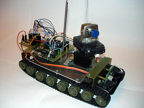
To begin with, our robot will be able to simply go around obstacles, that is, to repeat the normal behavior of most animals in nature. All that we need for the construction of such a robot can be found in radio stores. Decide how our robot will move. I think the most successful tracks that are used in tanks are the most convenient solution, because the tracks have greater permeability than the wheels of the car and they are easier to manage (to turn it is enough to rotate the tracks in different directions). Therefore, you will need any toy tank, in which the tracks rotate independently of each other, such can be bought at any toy store at a reasonable price. From this tank you only need a platform with tracks and motors with gearboxes, the rest you can safely unscrew and throw out. We also need a microcontroller, my choice fell on the ATmega16 - it has enough ports to connect sensors and peripherals, and in general it is quite convenient. You also need to buy some radio components, a soldering iron, a multimeter.
')
We make a fee with MK
Robot layout
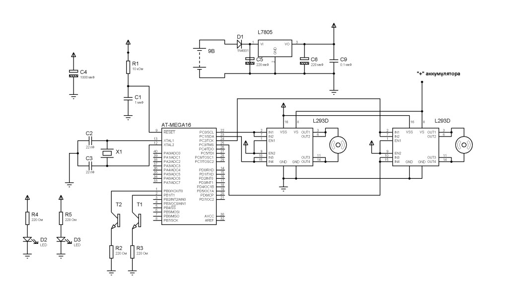
In our case, the microcontroller will perform the functions of the brain, but we will not start with it, but with the power supply of the robot's brain. Proper nutrition is a guarantee of health, so we will start with how to properly feed our robot, because this is usually where novice robot builders are mistaken. And in order for our robot to work normally you need to use a voltage stabilizer. I prefer the L7805 chip - it is designed to produce a stable 5V voltage at the output, which is what our microcontroller needs. But due to the fact that the voltage drop on this chip is about 2.5V, it needs to be served at least 7.5V. Along with this stabilizer, electrolytic capacitors are used to smooth out voltage ripples and a diode must be included in the circuit to protect against polarity reversal.
Now we can do our microcontroller. The case at MK - DIP (it is more convenient to solder it) and has forty conclusions. There is an ADC, PWM, USART and many other things on board that we will not use for now. Consider a few important nodes. The RESET pin (the 9th leg of the MK) is pulled up by the resistor R1 to the “plus” of the power source - this must be done! Otherwise, your MC can inadvertently be dropped or, more simply, buggy. Also a desirable measure, but not mandatory, is to connect the RESET via the ceramic capacitor C1 to the “ground”. In the diagram, you can also see the electrolyte at 1000 microfarad, it saves from voltage dips when the engines run, which will also have a positive effect on the operation of the microcontroller. The quartz resonator X1 and the capacitors C2, C3 should be located as close as possible to the terminals XTAL1 and XTAL2.
I will not talk about how to flash the MK, since you can read about it on the Internet. We will write the program in C, and I chose CodeVisionAVR as the programming environment. This is a fairly convenient environment and is useful for beginners, because it has a built-in wizard for creating code.
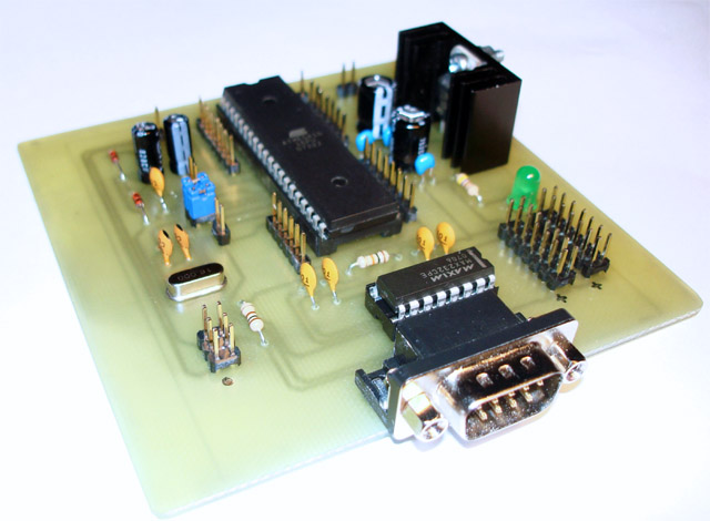
My robot fee
Engine control
An equally important component in our robot is the engine driver, which makes it easier for us to manage it. Never and in no case can you connect the engines directly to the MK! In general, powerful loads cannot be controlled directly from the microcontroller, otherwise it will burn. Use key transistors. For our case there is a special chip - L293D. In such simple projects, always try to use this particular chip with the “D” index, since it has built-in diodes for protection against overloads. This microcircuit is very easy to manage and just get it in radio stores. It comes in two DIP and SOIC packages. We will use the DIP package because of the convenience of on-board installation. L293D has a separate power supply of engines and logic. Therefore, we will power the microcircuit from the stabilizer (VSS input), and the motors directly from the batteries (VS input). L293D withstands a load of 600 mA per channel, and it has two channels, that is, two engines can be connected to one microcircuit. But in order to be safe, we will unite the channels, and then it will take one micro for each engine. It follows that the L293D will be able to withstand 1.2 A. To achieve this, it is necessary to combine the feet of the micro, as shown in the diagram. The microcircuit works in the following way: when a logical “0” is applied to IN1 and IN2, and a logical unit to IN3 and IN4, the motor rotates in one direction, and if the signals are inverted, a logical zero is applied, then the motor will begin to rotate in the other direction. Conclusions EN1 and EN2 are responsible for enabling each channel. We connect them and connect them to the "plus" power from the stabilizer. Since the microcircuit heats up during operation, and the installation of radiators is problematic for this type of case, the heat is provided by the GND legs - they are best unsoldered in a wide contact area. That's all for the first time you need to know about the drivers of engines.
Obstacle sensors
So that our robot can navigate and not hit everything, we will install two infrared sensors on it. The simplest sensor consists of an IR diode, which emits in the infrared spectrum and a phototransistor, which will receive a signal from an IR diode. The principle is this: when there is no barrier in front of the sensor, the infrared rays do not fall on the phototransistor and it does not open. If there is an obstacle in front of the sensor, then the rays from it are reflected and fall on the transistor - it opens and the current begins to flow. The disadvantage of such sensors is that they can react differently to different surfaces and are not protected from interference - the sensor, incidentally, may be triggered by extraneous signals from other devices. It can protect against signal modulation, but for the time being we will not be bothered by this. To begin with, that's enough.
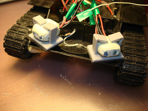
The first sensor version of my robot
Robot firmware
To revive the robot, for it you need to write the firmware, that is, a program that would take readings from the sensors and control the engines. My program is the simplest, it does not contain complex structures and will be clear to everyone. The following two lines include header files for our microcontroller and commands for generating delays:
#include <mega16.h>
#include <delay.h>
The following lines are conditional, because the PORTC values depend on how you connected the driver of the motors to your microcontroller:
PORTC.0 = 1;
PORTC.1 = 0;
PORTC.2 = 1;
PORTC.3 = 0;
The value 0xFF means that the output will be a log. "1", and 0x00 - log. "0".
With the following construction we check whether there is an obstacle in front of the robot and from which side it is:
if (!(PINB & (1<<PINB.0)))
{
...
}
If the phototransistor gets the light from the infrared diode, then a log is set on the foot of the microcontroller. “0” and the robot begins to move backward to move away from the obstacle, then turns around, so as not to encounter an obstacle again and then goes forward again. Since we have two sensors, we check the presence of an obstacle twice - on the right and on the left and therefore we can find out from which side the obstacle. The command “delay_ms (1000)” indicates that one second will elapse before the next command is executed.
Conclusion
I have covered most of the aspects that will help you assemble your first robot. But this robot does not end there. If you assemble this robot, then you will have a lot of opportunities to expand it. You can improve the algorithm of the robot, such as what to do if the obstacle is not from some side, but directly in front of the robot. It also does not hurt to install the encoder - a simple device that will help accurately locate and know the location of your robot in space. For clarity, you can install a color or monochrome display, which can show useful information - battery charge level, distance to obstacles, various debugging information. Improvement of sensors will not hurt either - installation of a TSOP (these are infrared receivers that perceive the signal only at a certain frequency) instead of ordinary phototransistors. In addition to infrared sensors, ultrasound sensors exist, they are more expensive, and they are also not without drawbacks, but recently they are gaining popularity among robot builders. In order that the robot could react to a sound, it would be quite good to install microphones with the amplifier. But the really interesting, I think, is the installation of the camera and the programming of computer vision based on it. There is a set of special libraries OpenCV, with which you can program the recognition of faces, movements in colored beacons and a lot of interesting things. It all depends on your imagination and skills.
List of components:
- ATmega16 in DIP-40 package>
- L7805 in TO-220 package
- L293D in DIP-16 package x2 pcs.
- 0.25 W resistors with nominal values: 10 kΩ x1 pcs., 220 Ohm x4 pcs.
- ceramic capacitors: 0.1 microfarad, 1 microfarad, 22 pF
- electrolytic capacitors: 1000 microfarad x 16 V, 220 microfarad x 16V x2 pcs.
- diode 1N4001 or 1N4004
- 16 MHz crystal
- IR diodes: any suitable in the amount of two pieces.
- phototransistors, also any, but reacting only to the wavelength of infrared rays
Firmware code:
/*****************************************************


: ATmega16
: 16,000000 MHz
, :
Project -> Configure -> "C Compiler"
*****************************************************/

#include <mega16.h>
#include <delay.h>

void main(void)
{
//
//
DDRB=0x00;
//
PORTB=0xFF;

//
//
DDRC=0xFF;

// .
//
while (1)
{
//
PORTC.0 = 1;
PORTC.1 = 0;
PORTC.2 = 1;
PORTC.3 = 0;
if (!(PINB & (1<<PINB.0))) //
{
// 1
PORTC.0 = 0;
PORTC.1 = 1;
PORTC.2 = 0;
PORTC.3 = 1;
delay_ms(1000);
//
PORTC.0 = 1;
PORTC.1 = 0;
PORTC.2 = 0;
PORTC.3 = 1;
delay_ms(1000);
}
if (!(PINB & (1<<PINB.1))) //
{
// 1
PORTC.0 = 0;
PORTC.1 = 1;
PORTC.2 = 0;
PORTC.3 = 1;
delay_ms(1000);
//
PORTC.0 = 0;
PORTC.1 = 1;
PORTC.2 = 1;
PORTC.3 = 0;
delay_ms(1000);
}
};
}
About my work
At the moment, my robot is almost complete.
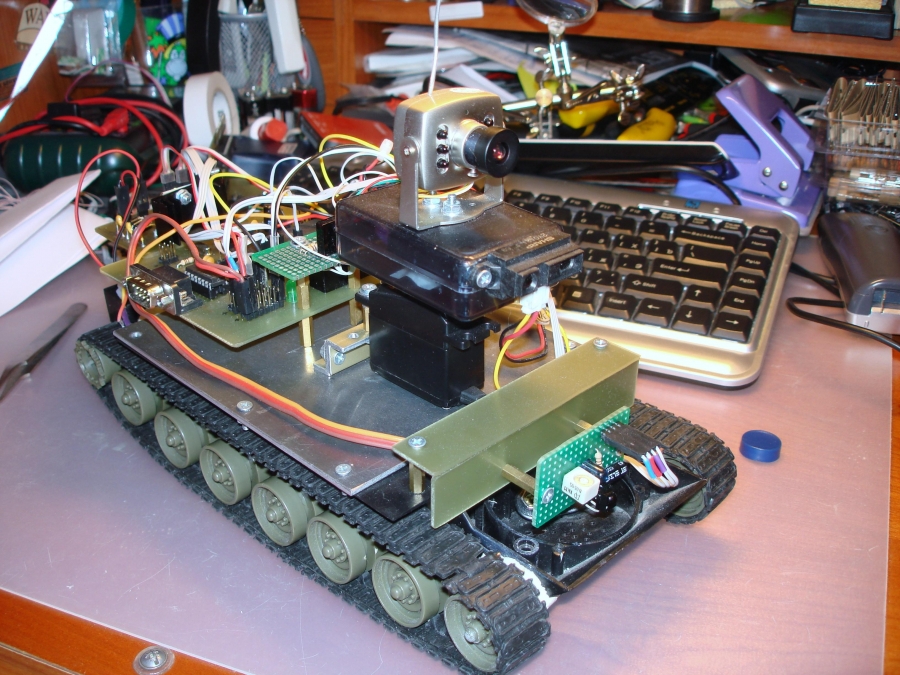
It is equipped with a wireless camera, a distance sensor (both the camera and this sensor are installed on the rotary tower), an obstacle sensor, an encoder, a receiver of signals from the console and an RS-232 interface for connecting to a computer. It works in two modes: autonomous and manual (it receives control signals from the remote control), the camera can also be turned on / off remotely or by the robot itself to save battery power. I am writing firmware to protect the apartment (image transfer to a computer, motion detection, detour around the room).
If you wish, I post the video:
UPD. I reloaded the photos and made small corrections in the text.
The article was published by me in the magazine "Hacker" in August 2009.
Source: https://habr.com/ru/post/76128/
All Articles