SketchFlow: prototyping interfaces in a new way
All the good developers and designers with whom I am familiar, in one way or another, are engaged in prototyping . It seems to me that prototyping resembles a channel between a customer and a developer through which ideas and feedback from interested parties are transmitted, which allows making changes to a project at an early stage of development.
As you may have noticed, prototypes can be presented in a variety of forms: from some sketches on a napkin to a design created in a professional package that looks very close to the desired result. Despite this number of options, we can distinguish two main types of prototypes: low-fidelity and high fidelity. An unreliable prototype is a simple description, a sketch on a drawing board or sketch, which roughly shows a piece of the user interface. An example of such a prototype is presented in Fig. one.
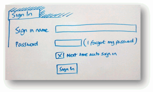
Fig. 1 - An example of an unreliable prototype that demonstrates the login form
')
The prototype is called unreliable, because its main function is to show a piece of functionality in its simplest form without focusing on icons, colors, fonts and the like.
The opposite of the unreliable prototype is a highly reliable prototype. Such a prototype, for example, as shown in Fig. 2, is still a prototype, in which there is no functionality and behavior, but it looks very close to the finished product.
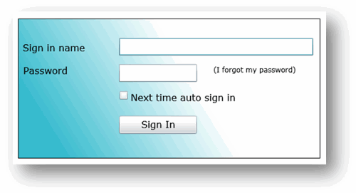
Fig. 2 - An example of a highly reliable prototype
Both types of prototypes find their use in the development cycle.
Little reliable prototypes in the work are very effective for obtaining user feedback on what they think about the concept without understanding the details. Since the prototype is actually a sketch, users tend to find it easier to give feedback on it. However, it is worth noting that there are situations when, when an improper prototype does not fit. There was a case when once I spoke to the authorities at a meeting. And since my materials were inadequate prototypes, my presentation was met with perplexed views, when the only thing I showed was a folding poster. The authorities probably thought: “We are paying you for writing programs?”.
As you might guess, highly reliable prototypes have the opposite problem. Although they perfectly show how everything will look in the final product, the induced beauty and gloss can become excessive for most users. I have come across cases where users were simply afraid to ask for major changes in the highly reliable prototype, because they assumed that it might take a lot of effort or time. Users believed that since the prototype looks close to what a finished product should look like, it means that significant work has already been done and they tried not to request new changes. In addition, a highly reliable prototype forced users to talk about design when talking to them, such as “shouldn't this blue shadow be in the style of our logo?” Instead of focusing users on the overall design and layout of the form.
Moreover, even the demonstration of any kind of prototype can be difficult, especially when the user is at a remote distance. Often, we had to insert screenshots into PowerPoint and send them without the opportunity to tell the user about the details or explain some points of the design.
To solve some of these prototyping problems, in March 2009, at the MIX09 conference, Microsoft announced a new technology called SketchFlow, which is part of Expression Blend 3. According to the description of the head of the development team, Christian Schormann (Christian Schormann), which he placed In my blog, SketchFlow is a fun, informal, flexible, fast and powerful way to create dynamic sketches and prototypes with rich features in Expression Blend.
In this article, we explore the functionality of SketchFlow by looking at how it works and how this type of tool can make your prototypes more useful and efficient.
If you have heard about the Expression product family, then you probably know that Expression Blend is a tool for designers. And although designers are the main users of Blend [app. Transl .: Blend 3 includes tools for development, so Blend has ceased to be a tool aimed at designers], I think that the SketchFlow functionality can offer seductive features for many developers — many of whom sometimes do prototyping using mockups ( mockups) visual basic or other tools.
Expression Blend 3 supports two different types of SketchFlow projects. The first is WPF applications, and the second is Silverlight with hosting in a web browser. Both types of projects provide the same functionality, only the proposed set of controls will differ depending on the chosen platform.
After creating a new project in Expression Blend 3, the first component you'll see is “Application Flow”. Application Flow is a panel in Blend that allows you to create a simple representation of the data flows in your application.

Fig. 3 - The simplest data stream for an online store
As shown in the diagram above, Application Flow is used to create a simple workspace to navigate your prototype screens. The diagram defines five elements of a simple online store: the main window (storefront screen), the navigation window (browse screen), the shopping cart (checkout screen), the login window and the product confirmation window (shipping confirmation screen). Windows are connected by single or bidirectional lines that reflect the path that the application user must follow.
Creating such a flowchart will automatically create several empty XAML files in the Expression Blend project.
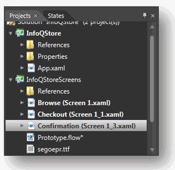
Fig. 4 - When creating a flowchart, empty XAML files are automatically created.
After creating the application threads, we can start adding controls to each of the prototype screens.
If you've tried previous versions of Expression Blend, you probably know that you can drag controls from set to form to create a user interface.

Fig. 5 - Standard controls
You will be right if you look at pic. 5 you say that we started to make a highly reliable prototype.
In order to give it less confidence, SketchFlow introduces a new XAML style called “WigglyStyles”. As you understand from the name [approx. Translation: translation is difficult, so we will understand from the image], the new style imitates the simplest display option that could have been made when creating a sketch on a napkin. For more effect, SketchFlow contains support for a couple of new fonts, in the style of handwriting and architectural sketch. By applying controls with the WigglyStyles style, we end up with a completely different effect.

Fig. 6. - WigglyStyles Style Controls
It is important to keep in mind that these controls are fully operational, and not simple images. Text can be entered into text fields, buttons can be pressed, scrollbars can be moved and, as a result, a very functional, but at the same time, unreliable prototype will appear.
Now that we’ve dealt with data streams and styles, let's get down to the design of our prototype. In this article, we will create a prototype for the new “InfoQ” store, which should serve to sell a variety of products under the well-known brand InfoQ [app. Trans.: this is such a humor, InfoQ is the site on which the article is posted, quite famous, by the way].
After determining the flow of data between the screens, we still have not added navigation. Let's say by clicking on the “Trash” button I want to go to the prototype screen of the trash.
In previous versions of Expression Blend, which is true for many other user interface development tools, creating navigation often involves setting up an action or event and writing code to handle the navigation. This is not very difficult if you are a developer, but not at all intuitive for designers or those who are not familiar with the development, moreover, completely unnecessary code for the task, slows down the development of the prototype.
Fortunately, Expression Blend approaches navigation in a different way. By clicking on any control element with the right button, you can call the context menu to set the navigation, as shown in Fig. 7
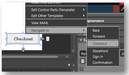
Fig. 7. - Context menu “Navigate to” in Expression Blend
Selecting any option in the menu will automatically generate a trigger for the control. In the XAML code, it will look like this:
The XAML part responsible for navigation is the interaction trigger, which contains an “EventName” for determining the event of the triggering trigger and “NavigateToScreenAction”, which contains the target screen for the transition. All this XAML code is generated automatically and you do not have to enter a single line of code.
Another part of SketchFlow navigation is the concept of a composite screen. If you have experience in web development, then you are most likely familiar with the need to solve the problem of the same set of controls for different pages. This can be a common set of tabs or buttons at the top of a page, or a generic-looking design that all pages inherit.
In SketchFlow, this mechanism is a composition screen. A composition screen is a collection of XAML objects that can be displayed on any page. To create a composite screen, first of all you need to set a set of controls.

Fig. 8 - The total set of controls that we want to show on each page
In fig. 8 presents four buttons: one to return to the home page, one to display the page with goods, one to go to the account page and another one to go to the cart page. To display these elements on each of our screens, we must select all of them, right-click and select the “Make Into Composition Screen ...” menu item as shown in Figure. 9.
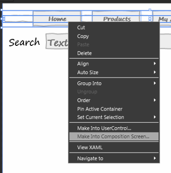
Fig. 9 - Creating a composition screen based on buttons
After entering the name of the composition screen (I called it “TopBanner”), the controls will form a separate XAML file, and the composition screen will be displayed in Application Flow.
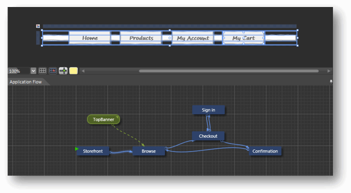
Fig. 10 - Composition Screen and Application Flow
As you can see in fig. The TopBanner 10 compositional screen is now displayed in application flow (green highlights compositional screens from blue navigation screens). To bind the composition screen to other XAML pages, we can create links between the composition screen and navigation screens.
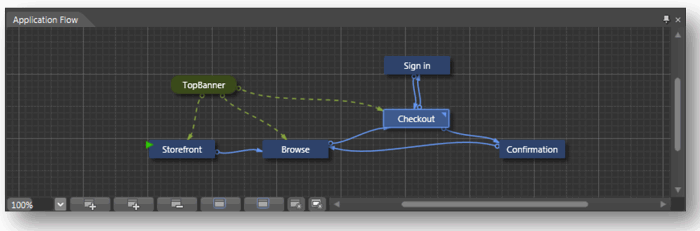
Fig. 11 - Linking a composite screen to navigation screens
In fig. Figure 11 shows that the composition screen is now used in storefront, browse, and checkout screens.
We have added some controls to the InfoQ store and are now ready to show a prototype to users to get feedback from them.
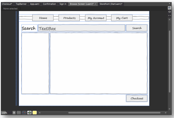
Fig. 12 - Completed form that we will show users
As you probably know, pressing F5 will build our application. But this will not happen as you expect. The application will start, but in the context of a SketchFlow-player, which will allow users to manage the application and leave feedback directly in the process of learning.

Fig. 13 - Application running in the context of a SketchFlow player
As shown in fig. 13, the user is able to use the prototype navigation in three different ways. The navigate tab on the left shows the screens available to the user to the user. The buttons that we configured for navigation also work. The last third way to navigate is to explore the application flow in the lower left window by going to the FLOW tab. The Flow tab shows the application flow in almost the same form in which we created it (Fig. 14).
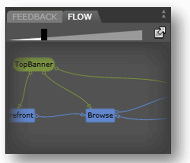
Fig. 14 - Tab Flow shows application flow
While navigating the prototype, SketchFlow player allows the user to leave comments and feedback on the design in two ways, by typing the review text in the feedback window (for example, the user can leave a question or just a review on the prototype). And the second way - the user can draw on the screen using the “pen” and “marker” tools. Both ways to provide feedback are shown in Fig. 15.
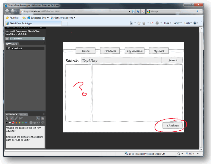
Fig. 15 - User Reviews
User feedback on the best arrangement of controls or windows can be very helpful. This review will be saved as a file with the “.feedback” extension, which can later be uploaded to the site or sent by email to the development team. When developers get the feedback file, it can be imported into Expression Blend and used as an overlay for the project, thus allowing the team to get feedback and user comments as an overlay on the original prototype.
Previously, we looked at navigation between windows. But how about showing the user a message or animation that does not constitute a navigation window? For example, when a user clicks on the “add cart” button in the InfoQ Store, we may want to display a message confirming that the product has been successfully added to the basket. This does not require a separate screen, but we must do some actions to process the response from the prototype. In SketchFlow, this mechanism is known as a change of state.
States are created using the States tab.
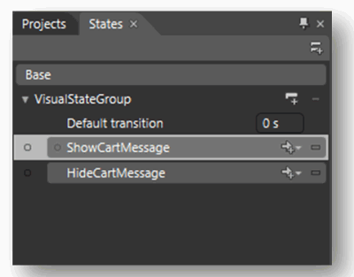
Fig. 16 - Two states for displaying and hiding the “added to cart” message
Notice in the example above, I created two states: ShowCartMessage and HideCartMessage. I can determine what should happen for each of the states. For ShowCartMessage, I created a simple dialog that contains a message stating that the product has been added to the cart and has a transparency of 100% (Fig. 17).
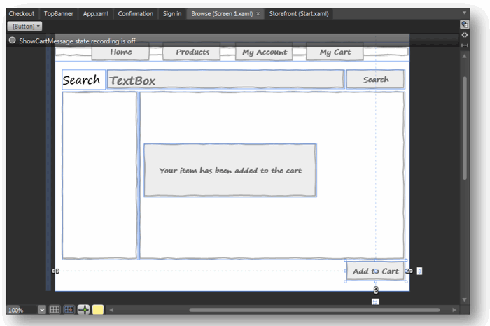
Fig. 17 - Simple dialogue
For the HideCartMessage state, I, on the contrary, set the transparency of the dialog to 0%, creating the effect that the dialog disappears.
Just like before, I worked with controls and navigation, using the context menu, I simply bind the state to the control. This time, when the user clicks on the “add to cart” button, the ShowCartMessage state is activated and the dialog appears on the screen.

Fig. 18 - Snap state to button
In the same way, the action is attached to the dialogue, so that when the user clicks somewhere outside the dialogue, the message disappears.
As with the creation of navigation, binding to a state creates a XAML code for each control. The mechanism that controls the state is the ActivateStateAction:
For more effect, states support animation transformations. For example, if your prototype should show or hide a dialogue with a slowdown, then for this we can create a XAML storyboard that will perform the task. As you probably understood everything created in SketchFlow, created using XAML - there are no hidden mechanisms or options - this means that everything you do in the XAML markup will be reflected in the prototype, even if this function is not supported by adding in the designer .
Up to this point, we have considered adding controls and navigation, but a very important element of many prototypes is also filling in test data - in our example this could be a list of products that we sell at the InfoQ store.
Previous versions of Expression Blend supported connecting to external data sources through a direct connection to a database or CLR objects, but this exercise can take too much time, especially when creating prototypes. This alone may cause the prototype to be rejected; in addition, it creates unnecessary inconvenience in the requirement to create databases, schemas, tables only in order to obtain data for several simple objects.
To solve this problem, Expression Blend 3 supports the ability to create test data directly from the designer. This becomes possible with the addition of a new data source in the Data tab.

Fig. 19 - Options for test data
Two variants of defining test data are supported: create a new data set or import data from an XML file. The second method can be especially useful when you have an XML file with data from some internal system, for example, the result of exporting data from a current version of a business application or even from a public RSS feed.
We don’t have XML source for our prototype, so I’ll define some test data in the first way.

Fig. 20 - Test data set for our store
To demonstrate our store, a set of data has been created that demonstrate products. Keep in mind that test cases can be presented in several forms. For example, SKU is presented here as a text field, and the Image field is presented as an image as a png file from disk (an image folder can be imported into a test data set).
Now that we have the data structure defined, we can define a test data set for the store.
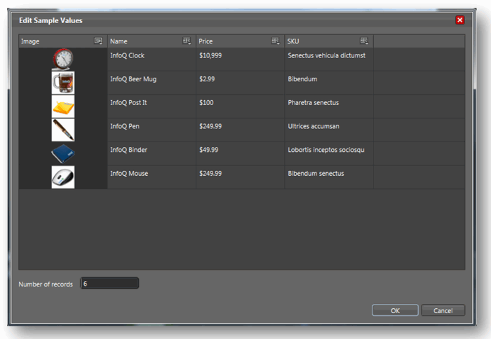
Fig. 21 - Editing test data
Here you need to take into account that in addition to the entered fixed values, Blend also supports automatically generated values for different types.
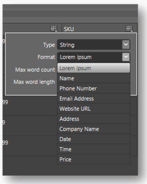
Fig. 22 - Automatically generated values
This feature is especially useful when you are working on a prototype that displays a list of made-up phone numbers, URLs, email addresses, and so on.
When the work with the definition of test data is completed, the next step is to drag the dataset from the panel to the desired screen element so that it has data. When the prototype application is launched, all test data will appear in the prototype.

Fig. 23 - Transfer of test data from the panel to the screen element
I know only a few people who really enjoy documenting projects, including prototypes. However, documentation can be critical, especially for prototypes, as it provides records about the location of prototype elements, user feedback, and prototype states.
If you fall under the category of documentaries, then one of the features of Expression Blend 3 will be to your liking. This is the “Export to Microsoft Word” option in the File menu.
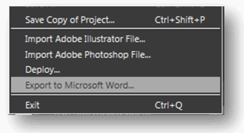
Fig. 24 - Option “Export to Microsoft Word ...”
This menu item allows you to generate a new word-document for all elements of your prototype.
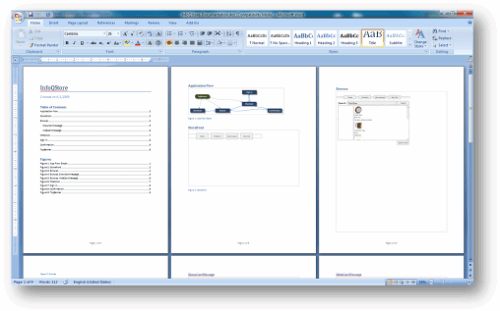
Fig. 25 - Example
It includes both application flow and screen layout and user feedback and status. All this has content and a list of all images. All this information in word format allows you to easily apply your own documenting style and add your comments or data for later sending information to the client. [approx. Transl .: Export to Word really generates a very nice file, the mechanism is excellent].
In the end, the quality of the prototype can often be measured by the success of the final application. Which raises the question: “How can I transfer these prototypes to production?”. When I work with clients, I often see two approaches.
The first approach is to throw away all prototypes and use familiar tools, which is what they most often do today. So, the designer creates an on-screen representation (screen mockup) of an application in Photoshop, exports it to an image and gives it to the developer in such a way that he creates a real application. Most likely, this will lead to differences in the interpretation of what the designer wanted to say and what the developer will do, especially in the intricacies of the design.
The second approach is to keep as much of the prototypes as possible for further use in the steps of creating the application. Using SketchFlow, many visual solutions and controls can be used with replacing the application flow and navigating to another framework, such as MVC, simply translating states into code, embedding error handling, and so on. You should always keep a balance on how much you take from prototypes in production and how much is left overboard, but the interactive prototyping tool makes it much easier to find a compromise in this choice.
I hope this article was helpful to you and your understanding of the possibilities in SketchFlow. I hope you will agree that the new toolkit has every chance of becoming an assistant for designers and developers and will allow prototyping to a new level.
The translated article is based on a preview version of the SketchFlow tool. But having considered the final version, I did not find differences in the presented material.
Today Expression Studio 3 is already available in the final version, and with it Expression Blend 3 with SketchFlow. You can download the entire studio or Blend 3 at this address .
To continue exploring Expression Blend and SketchFlow, you can use the rich video content from TechDays.ru.
In addition, you can watch the video “SketchFlow: from concept to production” from the MIX '09 conference.
I hope that you liked the translation and you found the translation material useful and new to you. SketchFlow is an extremely interesting mechanism that offers a new approach in prototyping custom elements with convenient support for all stages, from demonstrating to the customer to writing documentation.

As you may have noticed, prototypes can be presented in a variety of forms: from some sketches on a napkin to a design created in a professional package that looks very close to the desired result. Despite this number of options, we can distinguish two main types of prototypes: low-fidelity and high fidelity. An unreliable prototype is a simple description, a sketch on a drawing board or sketch, which roughly shows a piece of the user interface. An example of such a prototype is presented in Fig. one.
Fig. 1 - An example of an unreliable prototype that demonstrates the login form
')
The prototype is called unreliable, because its main function is to show a piece of functionality in its simplest form without focusing on icons, colors, fonts and the like.
The opposite of the unreliable prototype is a highly reliable prototype. Such a prototype, for example, as shown in Fig. 2, is still a prototype, in which there is no functionality and behavior, but it looks very close to the finished product.
Fig. 2 - An example of a highly reliable prototype
Both types of prototypes find their use in the development cycle.
Little reliable prototypes in the work are very effective for obtaining user feedback on what they think about the concept without understanding the details. Since the prototype is actually a sketch, users tend to find it easier to give feedback on it. However, it is worth noting that there are situations when, when an improper prototype does not fit. There was a case when once I spoke to the authorities at a meeting. And since my materials were inadequate prototypes, my presentation was met with perplexed views, when the only thing I showed was a folding poster. The authorities probably thought: “We are paying you for writing programs?”.
As you might guess, highly reliable prototypes have the opposite problem. Although they perfectly show how everything will look in the final product, the induced beauty and gloss can become excessive for most users. I have come across cases where users were simply afraid to ask for major changes in the highly reliable prototype, because they assumed that it might take a lot of effort or time. Users believed that since the prototype looks close to what a finished product should look like, it means that significant work has already been done and they tried not to request new changes. In addition, a highly reliable prototype forced users to talk about design when talking to them, such as “shouldn't this blue shadow be in the style of our logo?” Instead of focusing users on the overall design and layout of the form.
Moreover, even the demonstration of any kind of prototype can be difficult, especially when the user is at a remote distance. Often, we had to insert screenshots into PowerPoint and send them without the opportunity to tell the user about the details or explain some points of the design.
To solve some of these prototyping problems, in March 2009, at the MIX09 conference, Microsoft announced a new technology called SketchFlow, which is part of Expression Blend 3. According to the description of the head of the development team, Christian Schormann (Christian Schormann), which he placed In my blog, SketchFlow is a fun, informal, flexible, fast and powerful way to create dynamic sketches and prototypes with rich features in Expression Blend.
In this article, we explore the functionality of SketchFlow by looking at how it works and how this type of tool can make your prototypes more useful and efficient.
If you have heard about the Expression product family, then you probably know that Expression Blend is a tool for designers. And although designers are the main users of Blend [app. Transl .: Blend 3 includes tools for development, so Blend has ceased to be a tool aimed at designers], I think that the SketchFlow functionality can offer seductive features for many developers — many of whom sometimes do prototyping using mockups ( mockups) visual basic or other tools.
SketchFlow - details
Expression Blend 3 supports two different types of SketchFlow projects. The first is WPF applications, and the second is Silverlight with hosting in a web browser. Both types of projects provide the same functionality, only the proposed set of controls will differ depending on the chosen platform.
After creating a new project in Expression Blend 3, the first component you'll see is “Application Flow”. Application Flow is a panel in Blend that allows you to create a simple representation of the data flows in your application.
Fig. 3 - The simplest data stream for an online store
As shown in the diagram above, Application Flow is used to create a simple workspace to navigate your prototype screens. The diagram defines five elements of a simple online store: the main window (storefront screen), the navigation window (browse screen), the shopping cart (checkout screen), the login window and the product confirmation window (shipping confirmation screen). Windows are connected by single or bidirectional lines that reflect the path that the application user must follow.
Creating such a flowchart will automatically create several empty XAML files in the Expression Blend project.
Fig. 4 - When creating a flowchart, empty XAML files are automatically created.
After creating the application threads, we can start adding controls to each of the prototype screens.
If you've tried previous versions of Expression Blend, you probably know that you can drag controls from set to form to create a user interface.
Fig. 5 - Standard controls
You will be right if you look at pic. 5 you say that we started to make a highly reliable prototype.
In order to give it less confidence, SketchFlow introduces a new XAML style called “WigglyStyles”. As you understand from the name [approx. Translation: translation is difficult, so we will understand from the image], the new style imitates the simplest display option that could have been made when creating a sketch on a napkin. For more effect, SketchFlow contains support for a couple of new fonts, in the style of handwriting and architectural sketch. By applying controls with the WigglyStyles style, we end up with a completely different effect.
Fig. 6. - WigglyStyles Style Controls
It is important to keep in mind that these controls are fully operational, and not simple images. Text can be entered into text fields, buttons can be pressed, scrollbars can be moved and, as a result, a very functional, but at the same time, unreliable prototype will appear.
Add navigation
Now that we’ve dealt with data streams and styles, let's get down to the design of our prototype. In this article, we will create a prototype for the new “InfoQ” store, which should serve to sell a variety of products under the well-known brand InfoQ [app. Trans.: this is such a humor, InfoQ is the site on which the article is posted, quite famous, by the way].
After determining the flow of data between the screens, we still have not added navigation. Let's say by clicking on the “Trash” button I want to go to the prototype screen of the trash.
In previous versions of Expression Blend, which is true for many other user interface development tools, creating navigation often involves setting up an action or event and writing code to handle the navigation. This is not very difficult if you are a developer, but not at all intuitive for designers or those who are not familiar with the development, moreover, completely unnecessary code for the task, slows down the development of the prototype.
Fortunately, Expression Blend approaches navigation in a different way. By clicking on any control element with the right button, you can call the context menu to set the navigation, as shown in Fig. 7
Fig. 7. - Context menu “Navigate to” in Expression Blend
Selecting any option in the menu will automatically generate a trigger for the control. In the XAML code, it will look like this:
  <Button FontSize = "20" Height = "34" HorizontalAlignment = "Right" Margin = "0,0,8,19" Style = "{StaticResource Wiggle_ButtonStyle}" VerticalAlignment = "Bottom" Width = "105" Content = "Checkout ">
	 <i: Interaction.Triggers>
		 <i: EventTrigger EventName = "Click">
	 <Microsoft_Expression_Prototyping_Behavior: NavigateToScreenAction TargetScreen = "InfoQStoreScreens.Screen_1_1" />
		 </ i: EventTrigger>
	 </i:Interaction.Triggers>
 </ Button>
The XAML part responsible for navigation is the interaction trigger, which contains an “EventName” for determining the event of the triggering trigger and “NavigateToScreenAction”, which contains the target screen for the transition. All this XAML code is generated automatically and you do not have to enter a single line of code.
Add a composition screen
Another part of SketchFlow navigation is the concept of a composite screen. If you have experience in web development, then you are most likely familiar with the need to solve the problem of the same set of controls for different pages. This can be a common set of tabs or buttons at the top of a page, or a generic-looking design that all pages inherit.
In SketchFlow, this mechanism is a composition screen. A composition screen is a collection of XAML objects that can be displayed on any page. To create a composite screen, first of all you need to set a set of controls.
Fig. 8 - The total set of controls that we want to show on each page
In fig. 8 presents four buttons: one to return to the home page, one to display the page with goods, one to go to the account page and another one to go to the cart page. To display these elements on each of our screens, we must select all of them, right-click and select the “Make Into Composition Screen ...” menu item as shown in Figure. 9.
Fig. 9 - Creating a composition screen based on buttons
After entering the name of the composition screen (I called it “TopBanner”), the controls will form a separate XAML file, and the composition screen will be displayed in Application Flow.
Fig. 10 - Composition Screen and Application Flow
As you can see in fig. The TopBanner 10 compositional screen is now displayed in application flow (green highlights compositional screens from blue navigation screens). To bind the composition screen to other XAML pages, we can create links between the composition screen and navigation screens.
Fig. 11 - Linking a composite screen to navigation screens
In fig. Figure 11 shows that the composition screen is now used in storefront, browse, and checkout screens.
We get feedback from users
We have added some controls to the InfoQ store and are now ready to show a prototype to users to get feedback from them.
Fig. 12 - Completed form that we will show users
As you probably know, pressing F5 will build our application. But this will not happen as you expect. The application will start, but in the context of a SketchFlow-player, which will allow users to manage the application and leave feedback directly in the process of learning.
Fig. 13 - Application running in the context of a SketchFlow player
As shown in fig. 13, the user is able to use the prototype navigation in three different ways. The navigate tab on the left shows the screens available to the user to the user. The buttons that we configured for navigation also work. The last third way to navigate is to explore the application flow in the lower left window by going to the FLOW tab. The Flow tab shows the application flow in almost the same form in which we created it (Fig. 14).
Fig. 14 - Tab Flow shows application flow
While navigating the prototype, SketchFlow player allows the user to leave comments and feedback on the design in two ways, by typing the review text in the feedback window (for example, the user can leave a question or just a review on the prototype). And the second way - the user can draw on the screen using the “pen” and “marker” tools. Both ways to provide feedback are shown in Fig. 15.
Fig. 15 - User Reviews
User feedback on the best arrangement of controls or windows can be very helpful. This review will be saved as a file with the “.feedback” extension, which can later be uploaded to the site or sent by email to the development team. When developers get the feedback file, it can be imported into Expression Blend and used as an overlay for the project, thus allowing the team to get feedback and user comments as an overlay on the original prototype.
States and Transitions
Previously, we looked at navigation between windows. But how about showing the user a message or animation that does not constitute a navigation window? For example, when a user clicks on the “add cart” button in the InfoQ Store, we may want to display a message confirming that the product has been successfully added to the basket. This does not require a separate screen, but we must do some actions to process the response from the prototype. In SketchFlow, this mechanism is known as a change of state.
States are created using the States tab.
Fig. 16 - Two states for displaying and hiding the “added to cart” message
Notice in the example above, I created two states: ShowCartMessage and HideCartMessage. I can determine what should happen for each of the states. For ShowCartMessage, I created a simple dialog that contains a message stating that the product has been added to the cart and has a transparency of 100% (Fig. 17).
Fig. 17 - Simple dialogue
For the HideCartMessage state, I, on the contrary, set the transparency of the dialog to 0%, creating the effect that the dialog disappears.
Just like before, I worked with controls and navigation, using the context menu, I simply bind the state to the control. This time, when the user clicks on the “add to cart” button, the ShowCartMessage state is activated and the dialog appears on the screen.
Fig. 18 - Snap state to button
In the same way, the action is attached to the dialogue, so that when the user clicks somewhere outside the dialogue, the message disappears.
As with the creation of navigation, binding to a state creates a XAML code for each control. The mechanism that controls the state is the ActivateStateAction:
  <i: Interaction.Triggers>
	 <i: EventTrigger EventName = "Click">
	 <Microsoft_Expression_Prototyping_Behavior: ActivateStateAction TargetScreen = "InfoQStoreScreens.Screen_1" TargetState = "ShowCartMessage" />
	 </ i: EventTrigger>
 </i:Interaction.Triggers>
For more effect, states support animation transformations. For example, if your prototype should show or hide a dialogue with a slowdown, then for this we can create a XAML storyboard that will perform the task. As you probably understood everything created in SketchFlow, created using XAML - there are no hidden mechanisms or options - this means that everything you do in the XAML markup will be reflected in the prototype, even if this function is not supported by adding in the designer .
Add test data
Up to this point, we have considered adding controls and navigation, but a very important element of many prototypes is also filling in test data - in our example this could be a list of products that we sell at the InfoQ store.
Previous versions of Expression Blend supported connecting to external data sources through a direct connection to a database or CLR objects, but this exercise can take too much time, especially when creating prototypes. This alone may cause the prototype to be rejected; in addition, it creates unnecessary inconvenience in the requirement to create databases, schemas, tables only in order to obtain data for several simple objects.
To solve this problem, Expression Blend 3 supports the ability to create test data directly from the designer. This becomes possible with the addition of a new data source in the Data tab.
Fig. 19 - Options for test data
Two variants of defining test data are supported: create a new data set or import data from an XML file. The second method can be especially useful when you have an XML file with data from some internal system, for example, the result of exporting data from a current version of a business application or even from a public RSS feed.
We don’t have XML source for our prototype, so I’ll define some test data in the first way.
Fig. 20 - Test data set for our store
To demonstrate our store, a set of data has been created that demonstrate products. Keep in mind that test cases can be presented in several forms. For example, SKU is presented here as a text field, and the Image field is presented as an image as a png file from disk (an image folder can be imported into a test data set).
Now that we have the data structure defined, we can define a test data set for the store.
Fig. 21 - Editing test data
Here you need to take into account that in addition to the entered fixed values, Blend also supports automatically generated values for different types.
Fig. 22 - Automatically generated values
This feature is especially useful when you are working on a prototype that displays a list of made-up phone numbers, URLs, email addresses, and so on.
When the work with the definition of test data is completed, the next step is to drag the dataset from the panel to the desired screen element so that it has data. When the prototype application is launched, all test data will appear in the prototype.
Fig. 23 - Transfer of test data from the panel to the screen element
Documentation
I know only a few people who really enjoy documenting projects, including prototypes. However, documentation can be critical, especially for prototypes, as it provides records about the location of prototype elements, user feedback, and prototype states.
If you fall under the category of documentaries, then one of the features of Expression Blend 3 will be to your liking. This is the “Export to Microsoft Word” option in the File menu.
Fig. 24 - Option “Export to Microsoft Word ...”
This menu item allows you to generate a new word-document for all elements of your prototype.
Fig. 25 - Example
It includes both application flow and screen layout and user feedback and status. All this has content and a list of all images. All this information in word format allows you to easily apply your own documenting style and add your comments or data for later sending information to the client. [approx. Transl .: Export to Word really generates a very nice file, the mechanism is excellent].
From prototype to production
In the end, the quality of the prototype can often be measured by the success of the final application. Which raises the question: “How can I transfer these prototypes to production?”. When I work with clients, I often see two approaches.
The first approach is to throw away all prototypes and use familiar tools, which is what they most often do today. So, the designer creates an on-screen representation (screen mockup) of an application in Photoshop, exports it to an image and gives it to the developer in such a way that he creates a real application. Most likely, this will lead to differences in the interpretation of what the designer wanted to say and what the developer will do, especially in the intricacies of the design.
The second approach is to keep as much of the prototypes as possible for further use in the steps of creating the application. Using SketchFlow, many visual solutions and controls can be used with replacing the application flow and navigating to another framework, such as MVC, simply translating states into code, embedding error handling, and so on. You should always keep a balance on how much you take from prototypes in production and how much is left overboard, but the interactive prototyping tool makes it much easier to find a compromise in this choice.
Conclusion
I hope this article was helpful to you and your understanding of the possibilities in SketchFlow. I hope you will agree that the new toolkit has every chance of becoming an assistant for designers and developers and will allow prototyping to a new level.
From translator
The translated article is based on a preview version of the SketchFlow tool. But having considered the final version, I did not find differences in the presented material.
Today Expression Studio 3 is already available in the final version, and with it Expression Blend 3 with SketchFlow. You can download the entire studio or Blend 3 at this address .
To continue exploring Expression Blend and SketchFlow, you can use the rich video content from TechDays.ru.
In addition, you can watch the video “SketchFlow: from concept to production” from the MIX '09 conference.
I hope that you liked the translation and you found the translation material useful and new to you. SketchFlow is an extremely interesting mechanism that offers a new approach in prototyping custom elements with convenient support for all stages, from demonstrating to the customer to writing documentation.
Source: https://habr.com/ru/post/66367/
All Articles