How does a typical ISP (Internet Service Provider)
Many people wonder how the network of the provider is arranged or how they can build the network themselves, in this article I will show how the network is designed and works for me, at the logical level. Although I do not consider my structure to be ideal, it could have been done better, but this is mine :) because the truth is “ask 2 providers how to build a network - you will get 3 different options”
Now more about how it works.
A typical data network consists of 4 levels, many say that 3 but in fact there are 4 of them.
')
Level 1 - network boundary, i.e. butt with other operators, it’s a border
At this level, work is usually carried out with backbone operators from whom we take the Internet and operators by customers — who are given the Internet :) Interaction in 90% of cases is carried out using the BGP dynamic routing protocol
Level 2 is the very core of the network.
It includes billing, radius server, central switches where everything is stuck, NAT and shapers (with which we cut the band to the client. You can also cut on the port of the managed switch - but in this case local resources will be at the tariff speed, we also need to provide the tariff speed to the Internet and up to 100 Mbit within its network
The interaction between equipment usually also takes place using dynamic routing protocols such as BGP (in this case, internal BGP or OSPF), but there are also adherents of static routes.
Level 3 is the level of distribution, aggregation
This level usually usually includes managed switches (2nd or 3rd level) of a quarter or district, depending on the internal structure of the network. In my case, Layer 3 switches are installed and sometimes supplemented with Layer 2 switch, because with a VLAN scheme for a house - you should not rake the house owners in the network core
Level 4 - Access Level, Access, Client Access Point
These are the same house switches that are in the basements and in the attics of the houses in the drawer. Clients are already connected to them. In the CIS countries, the most commonly used is D-Link DES-3526, D-Link 3026 and slowly began to install D-Link DES-3028, for legal entities they usually already squeamish with longs and put Cisco Catalyst 2950
Now how it works for me:
1) Level 1 device
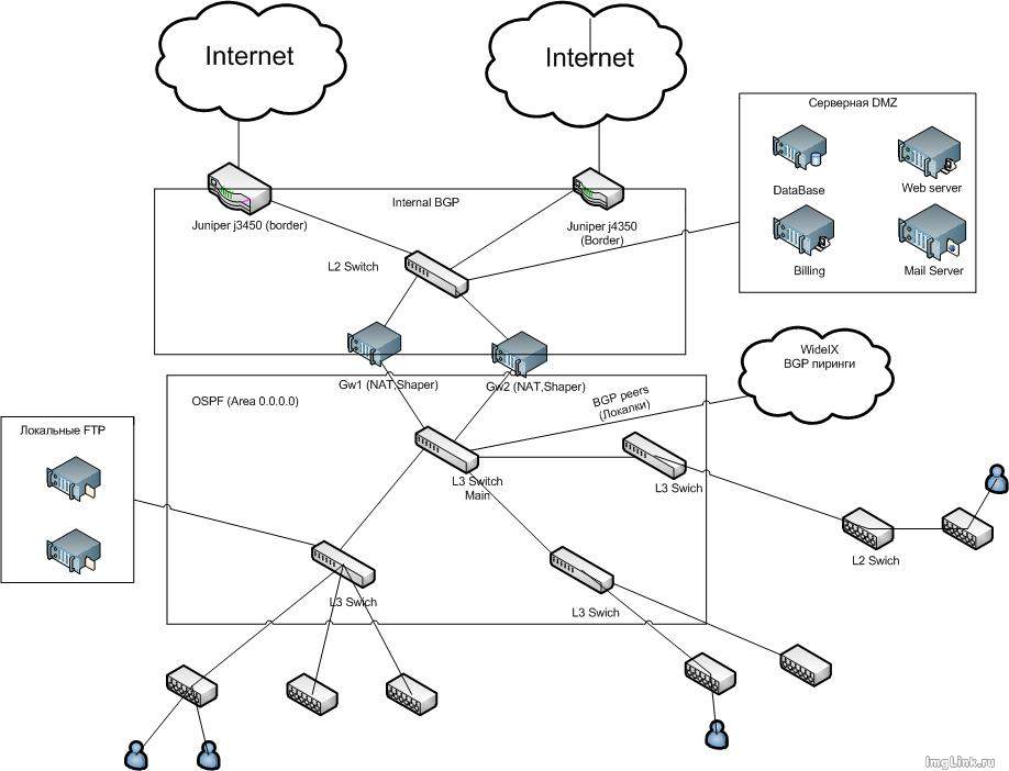
2 Juniper j4350 glands are used as border routers. Each of them is connected to its trunk uplink, interaction with uplinks is performed using the BGP protocol (ie, we give uplinks to the networks assigned to our AS (autonomous system) and we get from them a complete list of routes in the network Internet (full-view)
2) Level 2 device
At the second level, NAT-ing clients occur, tariff rate shaping and routing (Internet or peer-to-peer networks)
Two Intel's server platforms running under FreeBSD are used as NAT-shapers and shapers (NAT and cutting speeds are made on each of them and each of them reserves each other). Shaping is done using dummynet and tables (tablearg) and nat using pf
Also, between these routers and border routers (j4350), internal BGP runs so that in the event of a failure of one of the boarders, it switches quickly to the second and some traffic balancing is not superfluous either
Between routers and Layer 3 switches, OSPF runs to exchange intranet and peer-to-peer routes + we will announce the default route from them, that is, the default route. Router 1 has a metric of 100
Router 2 has a metric of 200, that is, in the event of a failure of one of the routers, all packets will go through back-ups (switching interval is about 10 seconds)
3) Level 3 device
With my home-based VLAN scheme, it is necessary to keep Layer 3 switches that route home networks and vlans at the distribution level.
IGMP snooping works on switches, all unnecessary multicast is truncated and Broadcasts and NetBIOS ports are cut (tcp / udp 135-139, 445)
4) Level 4 device
At the fourth level, there are D-Link DES-3526 switches, we plan to install DES-3028, because 4 Gigabit ports are very often needed. Yes, and according to rumors 3526 already EOL
Clients are directly connected to the switches, loopback detect is enabled on the subscriber pores (to disable ports with a loop), the maximum number of mac addresses on the port is 5, igmp snooping is enabled and the entire multicast is filtered except for the ranges 224.200.100.0-224.200.150.255 and 224.0.0.2 , so all broadcasts (except for the arp protocol) and the whole NetBIOS are killed.
And now the logical scheme of this whole business:
Now more about how it works.
A typical data network consists of 4 levels, many say that 3 but in fact there are 4 of them.
')
Level 1 - network boundary, i.e. butt with other operators, it’s a border
At this level, work is usually carried out with backbone operators from whom we take the Internet and operators by customers — who are given the Internet :) Interaction in 90% of cases is carried out using the BGP dynamic routing protocol
Level 2 is the very core of the network.
It includes billing, radius server, central switches where everything is stuck, NAT and shapers (with which we cut the band to the client. You can also cut on the port of the managed switch - but in this case local resources will be at the tariff speed, we also need to provide the tariff speed to the Internet and up to 100 Mbit within its network
The interaction between equipment usually also takes place using dynamic routing protocols such as BGP (in this case, internal BGP or OSPF), but there are also adherents of static routes.
Level 3 is the level of distribution, aggregation
This level usually usually includes managed switches (2nd or 3rd level) of a quarter or district, depending on the internal structure of the network. In my case, Layer 3 switches are installed and sometimes supplemented with Layer 2 switch, because with a VLAN scheme for a house - you should not rake the house owners in the network core
Level 4 - Access Level, Access, Client Access Point
These are the same house switches that are in the basements and in the attics of the houses in the drawer. Clients are already connected to them. In the CIS countries, the most commonly used is D-Link DES-3526, D-Link 3026 and slowly began to install D-Link DES-3028, for legal entities they usually already squeamish with longs and put Cisco Catalyst 2950
Now how it works for me:
1) Level 1 device
2 Juniper j4350 glands are used as border routers. Each of them is connected to its trunk uplink, interaction with uplinks is performed using the BGP protocol (ie, we give uplinks to the networks assigned to our AS (autonomous system) and we get from them a complete list of routes in the network Internet (full-view)
2) Level 2 device
At the second level, NAT-ing clients occur, tariff rate shaping and routing (Internet or peer-to-peer networks)
Two Intel's server platforms running under FreeBSD are used as NAT-shapers and shapers (NAT and cutting speeds are made on each of them and each of them reserves each other). Shaping is done using dummynet and tables (tablearg) and nat using pf
Also, between these routers and border routers (j4350), internal BGP runs so that in the event of a failure of one of the boarders, it switches quickly to the second and some traffic balancing is not superfluous either
Between routers and Layer 3 switches, OSPF runs to exchange intranet and peer-to-peer routes + we will announce the default route from them, that is, the default route. Router 1 has a metric of 100
Router 2 has a metric of 200, that is, in the event of a failure of one of the routers, all packets will go through back-ups (switching interval is about 10 seconds)
3) Level 3 device
With my home-based VLAN scheme, it is necessary to keep Layer 3 switches that route home networks and vlans at the distribution level.
IGMP snooping works on switches, all unnecessary multicast is truncated and Broadcasts and NetBIOS ports are cut (tcp / udp 135-139, 445)
4) Level 4 device
At the fourth level, there are D-Link DES-3526 switches, we plan to install DES-3028, because 4 Gigabit ports are very often needed. Yes, and according to rumors 3526 already EOL
Clients are directly connected to the switches, loopback detect is enabled on the subscriber pores (to disable ports with a loop), the maximum number of mac addresses on the port is 5, igmp snooping is enabled and the entire multicast is filtered except for the ranges 224.200.100.0-224.200.150.255 and 224.0.0.2 , so all broadcasts (except for the arp protocol) and the whole NetBIOS are killed.
And now the logical scheme of this whole business:
Source: https://habr.com/ru/post/62439/
All Articles