DisplayPort-LVDS
Good day, Habr!
And again I want to bring to your attention a hardware converter project, but now DisplayPort-LVDS is built on one (!) NXP chip.
Develop a simple DisplayPort-LVDS converter without firmware. Hardware implementation on an accessible element base. The converter must be universal, support various types of matrices (with single and dual channel LVDS) and voltage control signals of inverters. Work in the industrial temperature range. In general, like the HDMI-LVDS that was previously developed with the name "AHL-14.3." I also really wanted to achieve full compatibility between these controllers: pin-out, EDID firmware, overall dimensions and dimensions for embedding, etc. To reduce the cost of design, he refused DIP switches and 24V power supply support.
')
Googling a little, I realized that there are not so many solutions. The PTN3460 chip immediately caught my eye, he liked its dimensions 7x7mm (56-VFQFN) against my old solution (with HDMI), when there were two 13x13mm chips in S-PQFP-G100 packages.
It was with him (PTN3460) that he decided to start prototyping the board (however, he stopped at it for release, since its work did not cause any complaints). The PTN3460 chip is available for operation in two temperature ranges: from 0 and from -40 degrees.

Fig. 1. 3D model of the DisplayPort-LVDS top controller

Fig. 2. 3D model of the DisplayPort-LVDS bottom controller
The PTN3460 has a minimum wiring - it’s literally 10 ceramic capacitors and as many configuration resistors. I got a few more of them, because I wanted to achieve the most universal device with the configuration of all possible legs.
The 3.3V and 5V voltages are generated by STMicroelectronics (3A) ST1S10PHR converters - they have proven themselves well for a long time, and I continue to use them in my projects (by the way, also good feeders, but already at 4A this is ST1S41). The controller, as in the previous version, is STM32F100.
Already during debugging and refinement, the software began to use the built-in EEPROM for EDID. Previously, a chip was used, such as AT24C02 (or similar), where, in fact, the EDID was stored. PTN3460 allows you to place the EDID inside yourself, which saves us a little more cost.

Fig. 3. PTN3460 wiring diagram
Turning on the panel backlight and adjusting the brightness is carried out with a voltage of 3.3V. Switching on occurs by supplying a logical unit to a specific pin of the inverter, brightness control - using PWM. To control the buttons on the board are displayed (there is also a connector for connecting an external keyboard). The button handler and PWM are implemented on the STM32F100 controller, which also controls the LED indication (on / off / firmware EDID). It is worth noting that there are two types of backlight control (PWM): logical unit maximum brightness or logical zero maximum brightness. In this design, this is realized by switching jumpers with the corresponding designation on the board. A 3.3V / 5V / 12V / GND pin (via jumpers) was inserted into the LVDS connector on the board. The matrices often contain control pins: MAP (data card), BIT (bit selection), MODE (normal and mirror mode), etc. ... If you need to control these parameters, you can enter the corresponding matrix pin in the LVDS converter connector and change one of them .

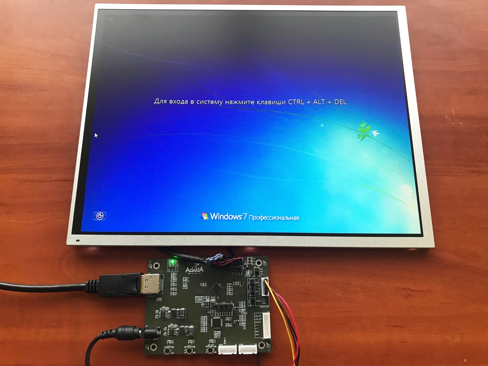
Fig. 4. DisplayPort-LVDS Controller Appearance
Converter configuration is as follows:

Fig. 5. Deltacast E-EDID Editor App
As I wrote above, I wanted to achieve full compatibility, including with the software part. In the firmware of the microcontroller, I had to change the EEPROM address (I did not change all the GPIO controls), but the EDID LOADER program came up unchanged. The converter is connected to the PC via UART using the USB-UART adapter. Next, select COM-port, a file with EDID and press the firmware button. On board there is an indication of firmware LED R_EE. When it goes off, the program on the PC issues messages about the end of the firmware. In case of unsuccessful firmware, an error message crashes.

Fig. 6. EDID LOADER app
At the moment, several boards have been produced for testing hardware and software.
The first iteration turned out with several wiring - I used the wrong pairs in the DisplayPort connector, and so, the device worked right away, no critical moments arose. The board immediately did on 4 layers in order to lay good landfills for food and land.
Thanks for attention!
PS. Anyone interested can see the new HDMI-LVDS article . Development on TSUMV59 from MStar
this controller has sound and OSD menus on board.
And again I want to bring to your attention a hardware converter project, but now DisplayPort-LVDS is built on one (!) NXP chip.
Formulation of the problem
Develop a simple DisplayPort-LVDS converter without firmware. Hardware implementation on an accessible element base. The converter must be universal, support various types of matrices (with single and dual channel LVDS) and voltage control signals of inverters. Work in the industrial temperature range. In general, like the HDMI-LVDS that was previously developed with the name "AHL-14.3." I also really wanted to achieve full compatibility between these controllers: pin-out, EDID firmware, overall dimensions and dimensions for embedding, etc. To reduce the cost of design, he refused DIP switches and 24V power supply support.
')
Primary requirements
- two LVDS channels (with the ability to switch and use one);
- two-pixel mode of operation of the converter;
- support for matrices of different bit sizes, ideally from 6 to 10;
- converter operating voltage 12V;
- panel operating voltage 3.3V, 5V, 12V;
- brightness control / backlight: 3.3V with the ability to invert;
Design Requirements
- simple (mechanical) configuration of the board (jumpers with a step of 2 mm);
- the geometric dimensions of the board must correspond to the board "AHL-14.3";
- on / off, brightness adjustment with buttons on the board;
- indication on / off / firmware EDID.
Search for a solution
Googling a little, I realized that there are not so many solutions. The PTN3460 chip immediately caught my eye, he liked its dimensions 7x7mm (56-VFQFN) against my old solution (with HDMI), when there were two 13x13mm chips in S-PQFP-G100 packages.
It was with him (PTN3460) that he decided to start prototyping the board (however, he stopped at it for release, since its work did not cause any complaints). The PTN3460 chip is available for operation in two temperature ranges: from 0 and from -40 degrees.
Fig. 1. 3D model of the DisplayPort-LVDS top controller
Fig. 2. 3D model of the DisplayPort-LVDS bottom controller
Element base selection
The PTN3460 has a minimum wiring - it’s literally 10 ceramic capacitors and as many configuration resistors. I got a few more of them, because I wanted to achieve the most universal device with the configuration of all possible legs.
The 3.3V and 5V voltages are generated by STMicroelectronics (3A) ST1S10PHR converters - they have proven themselves well for a long time, and I continue to use them in my projects (by the way, also good feeders, but already at 4A this is ST1S41). The controller, as in the previous version, is STM32F100.
Already during debugging and refinement, the software began to use the built-in EEPROM for EDID. Previously, a chip was used, such as AT24C02 (or similar), where, in fact, the EDID was stored. PTN3460 allows you to place the EDID inside yourself, which saves us a little more cost.
Fig. 3. PTN3460 wiring diagram
Control backlight and panel settings
Turning on the panel backlight and adjusting the brightness is carried out with a voltage of 3.3V. Switching on occurs by supplying a logical unit to a specific pin of the inverter, brightness control - using PWM. To control the buttons on the board are displayed (there is also a connector for connecting an external keyboard). The button handler and PWM are implemented on the STM32F100 controller, which also controls the LED indication (on / off / firmware EDID). It is worth noting that there are two types of backlight control (PWM): logical unit maximum brightness or logical zero maximum brightness. In this design, this is realized by switching jumpers with the corresponding designation on the board. A 3.3V / 5V / 12V / GND pin (via jumpers) was inserted into the LVDS connector on the board. The matrices often contain control pins: MAP (data card), BIT (bit selection), MODE (normal and mirror mode), etc. ... If you need to control these parameters, you can enter the corresponding matrix pin in the LVDS converter connector and change one of them .
Fig. 4. DisplayPort-LVDS Controller Appearance
Setup and first start
Converter configuration is as follows:
- The firmware of the controller is carried out according to the standard SWD.
- Set EDID parameters. The same Deltacast E-EDID Editor program comes to the rescue, in which we specify the matrix parameters from the datasheet (and sometimes by the selection method, since not all matrix manufacturers bother listing all the parameters).
Fig. 5. Deltacast E-EDID Editor App
As I wrote above, I wanted to achieve full compatibility, including with the software part. In the firmware of the microcontroller, I had to change the EEPROM address (I did not change all the GPIO controls), but the EDID LOADER program came up unchanged. The converter is connected to the PC via UART using the USB-UART adapter. Next, select COM-port, a file with EDID and press the firmware button. On board there is an indication of firmware LED R_EE. When it goes off, the program on the PC issues messages about the end of the firmware. In case of unsuccessful firmware, an error message crashes.
Fig. 6. EDID LOADER app
At the moment, several boards have been produced for testing hardware and software.
The first iteration turned out with several wiring - I used the wrong pairs in the DisplayPort connector, and so, the device worked right away, no critical moments arose. The board immediately did on 4 layers in order to lay good landfills for food and land.
Development benefits
- hardware implementation of the converter;
- universality;
- simplicity in setup.
Thanks for attention!
PS. Anyone interested can see the new HDMI-LVDS article . Development on TSUMV59 from MStar
this controller has sound and OSD menus on board.
Source: https://habr.com/ru/post/461801/
All Articles