Is it hard to write your first VHDL program?
Is it hard to write your first VHDL program? It's hard to say, but the main thing here is motivation ...
Maybe I could have managed to delay this moment, but a neighbor asked me to make a rectangular pulse generator so that it could be clearly displayed and it would be possible to control the frequency and duration of the pulse.
And with an accuracy of 0.1 microseconds ...
')
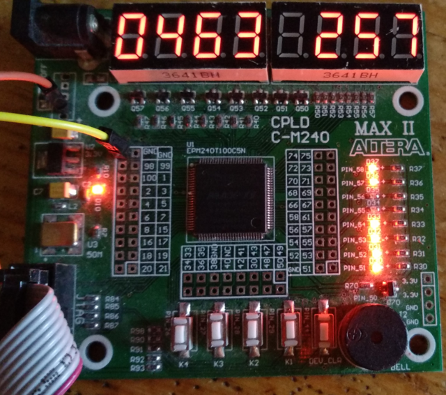
And my opinion fell on a scarf with CPLD (200 rubles, sort of) on which there were indicators and buttons. Once you should start working with such a thing, I thought, and ...
The choice on what to write VHDL or Verilog did not stand - although I write everything in C, but I still love Ada - so VHDL is unique. Moreover, having read the introduction to FPGA, I realized that nothing would be complicated (well, at least for such a simple task).
So, in thebeginning was the word we make ourselves a generator. The frequency of the native shred is 50 MHz, that is, we will reduce it to 10, so that the switching of the clock line will be in the middle and end. Here's what happened.
Then you need to somehow display and manage. We have two values - the length of the period and the length of the impulse, so that for the length of the period we assign 3 familiarities (taking into account tenths), and for the length of the period - 3.
Well, for control, signals from the buttons are suitable, which are visible at the bottom of the board - there are only 4 of them,
so let two control the change of period and momentum, respectively, one sets the sign of the change, and another one turns the output of the generator on and off ...
A little long and complicated (that's why it is folded up), but it’s quite understandable.
Well, we need to somehow display - we have a seven-segment indicator, and there are 6 of them (actually 8). We will display the time and, in order not to suffer with a point, in tenths of a microsecond.
Let them cycle through and display the current digit:
I admit honestly I dragged part of the code from the sources that came with a scarf - it’s very cool and clearly written! en_xhdl - this signal will control which indicator is on in the switching cycle, dataout_xhdl1 - this signal turns on the LEDs, well, data4 is a temporary register and stores a digit.
It remains to write a heart that considers everything - the generator itself. Here tactX is the display generator, and cnt is the pulse position counter. Well, lin is the signal of the generator itself.
Well, it remains to output the data - this is done constantly, so it should be located in the parallel execution block.
At the end, blind all processes together - the resulting Quarus Prime file was favorably received, compiled, and reported that
The most tedious stage remains, although it is completely graphic - to assign specific pins to the signals. And that’s all - it remains to pour everything into the device and check! Interestingly, we managed to keep within 229 cells, so there were still 11 left - but in reality, almost all gobbled up the interface - buttons and display. Actually the generator can be stacked in several cells - Intel has a document where they describe how to stack in 1 LUT - well, of course, without control ...
So, answering the question of the headline - no, it’s not difficult if you know C or Ada and you understand how digital electronics work, and yes, it’s difficult if you don’t have an idea of the basic things ... At least it took me a day to write, and I I got a lot of pleasure both from the development process, and from a functioning device! And the neighbor is happy :)
Maybe I could have managed to delay this moment, but a neighbor asked me to make a rectangular pulse generator so that it could be clearly displayed and it would be possible to control the frequency and duration of the pulse.
And with an accuracy of 0.1 microseconds ...
')
And my opinion fell on a scarf with CPLD (200 rubles, sort of) on which there were indicators and buttons. Once you should start working with such a thing, I thought, and ...
The choice on what to write VHDL or Verilog did not stand - although I write everything in C, but I still love Ada - so VHDL is unique. Moreover, having read the introduction to FPGA, I realized that nothing would be complicated (well, at least for such a simple task).
So, in the
-- 100 ns signal generator process(clk) variable t:integer range 0 to 5 := 0; begin if rising_edge(clk) then t := t + 1; if t = 5 then t := 0; tact <= not tact; end if; if t = 2 then tact <= not tact; end if; end if; end process; Then you need to somehow display and manage. We have two values - the length of the period and the length of the impulse, so that for the length of the period we assign 3 familiarities (taking into account tenths), and for the length of the period - 3.
shared variable period : integer range 0 to 1000 := 500; shared variable duty : integer range 0 to 1000 := 250; shared variable dig1:std_logic_vector(3 downto 0):="0000"; shared variable dig2:std_logic_vector(3 downto 0):="0101"; shared variable dig3:std_logic_vector(3 downto 0):="0010"; shared variable di1:std_logic_vector(3 downto 0):="0000"; shared variable di2:std_logic_vector(3 downto 0):="0000"; shared variable di3:std_logic_vector(3 downto 0):="0101"; Well, for control, signals from the buttons are suitable, which are visible at the bottom of the board - there are only 4 of them,
so let two control the change of period and momentum, respectively, one sets the sign of the change, and another one turns the output of the generator on and off ...
Here is the management
In management there are inc / dec procedures, here they are
process(key1) begin if rising_edge(key1) then ready <= not ready; end if; end process; process(key3) begin if rising_edge(key3) then if key4 = '1' then inc_duty; else dec_duty; end if; end if; end process; process(key2) begin if rising_edge(key2) then if key4 = '1' then inc_period; else dec_period; end if; end if; end process; In management there are inc / dec procedures, here they are
procedure inc_duty is begin if duty < period then duty := duty + 1; if dig1 = "1001" then dig1 := "0000"; if dig2 = "1001" then dig2 := "0000"; if dig3 = "1001" then dig3 := "0000"; else dig3 := dig3 + 1; end if; else dig2 := dig2 + 1; end if; else dig1 := dig1 + 1; end if; end if; end procedure; procedure dec_duty is begin if duty > 1 then duty := duty - 1; if dig1 = "0000" then dig1 := "1001"; if dig2 = "0000" then dig2 := "1001"; dig3 := dig3 - 1; else dig2 := dig2 - 1; end if; else dig1 := dig1 - 1; end if; end if; end procedure; procedure inc_period is begin if period < 1000 then period := period + 1; if di1 = "1001" then di1 := "0000"; if di2 = "1001" then di2 := "0000"; if di3 = "1001" then di3 := "0000"; else di3 := di3 + 1; end if; else di2 := di2 + 1; end if; else di1 := di1 + 1; end if; end if; end procedure; procedure dec_period is begin if period > 1 then period := period - 1; if di1 = "0000" then di1 := "1001"; if di2 = "0000" then di2 := "1001"; if di3 = "0000" then di3 := "1001"; else di3 := di3 - 1; end if; else di2 := di2 - 1; end if; else di1 := di1 - 1; end if; end if; end procedure; A little long and complicated (that's why it is folded up), but it’s quite understandable.
Well, we need to somehow display - we have a seven-segment indicator, and there are 6 of them (actually 8). We will display the time and, in order not to suffer with a point, in tenths of a microsecond.
Let them cycle through and display the current digit:
process(tactX) begin case tactX is when"000"=> en_xhdl<="11111110"; when"001"=> en_xhdl<="11111101"; when"010"=> en_xhdl<="11111011"; when"011"=> en_xhdl<="11110111"; when"100"=> en_xhdl<="11101111"; when"101"=> en_xhdl<="11011111"; when"110"=> en_xhdl<="10111111"; when"111"=> en_xhdl<="01111111"; when others => en_xhdl<="01111111"; end case; end process; process(en_xhdl) begin case en_xhdl is when "11111110"=> data4<=dig1; when "11111101"=> data4<=dig2; when "11111011"=> data4<=dig3; when "11110111"=> data4<="1111"; when "11101111"=> data4<=di1; when "11011111"=> data4<=di2; when "10111111"=> data4<=di3; when "01111111"=> data4<="0000"; when others => data4<="1111"; end case; end process; process(data4) begin case data4 is WHEN "0000" => dataout_xhdl1 <= "11000000"; WHEN "0001" => dataout_xhdl1 <= "11111001"; WHEN "0010" => dataout_xhdl1 <= "10100100"; WHEN "0011" => dataout_xhdl1 <= "10110000"; WHEN "0100" => dataout_xhdl1 <= "10011001"; WHEN "0101" => dataout_xhdl1 <= "10010010"; WHEN "0110" => dataout_xhdl1 <= "10000010"; WHEN "0111" => dataout_xhdl1 <= "11111000"; WHEN "1000" => dataout_xhdl1 <= "10000000"; WHEN "1001" => dataout_xhdl1 <= "10010000"; WHEN OTHERS => dataout_xhdl1 <= "11111111"; END CASE; END PROCESS; I admit honestly I dragged part of the code from the sources that came with a scarf - it’s very cool and clearly written! en_xhdl - this signal will control which indicator is on in the switching cycle, dataout_xhdl1 - this signal turns on the LEDs, well, data4 is a temporary register and stores a digit.
It remains to write a heart that considers everything - the generator itself. Here tactX is the display generator, and cnt is the pulse position counter. Well, lin is the signal of the generator itself.
process(tact) variable cntX : integer range 0 to 1000 := 0; variable cnt : integer range 0 to 1000 := 0; begin if rising_edge(tact) then if cntX = 0 then tactX <= tactX + 1; end if; cntX := cntX + 1; if cnt > period then cnt := 0; else cnt := cnt + 1; end if; if cnt = 0 then lin <= '0'; elsif cnt = duty then lin <= '1'; end if; end if; end process; Well, it remains to output the data - this is done constantly, so it should be located in the parallel execution block.
cat_led <= dataout_xhdl1; en_led <= en_xhdl; led1 <= not ready; out1 <= lin when ready = '1' else '0'; out2 <= not lin when ready = '1' else '0'; At the end, blind all processes together - the resulting Quarus Prime file was favorably received, compiled, and reported that
Top-level Entity Name v12 Family MAX II Device EPM240T100C5 Timing Models Final Total logic elements 229 / 240 ( 95 % ) Total pins 29 / 80 ( 36 % ) Total virtual pins 0 UFM blocks 0 / 1 ( 0 % ) The most tedious stage remains, although it is completely graphic - to assign specific pins to the signals. And that’s all - it remains to pour everything into the device and check! Interestingly, we managed to keep within 229 cells, so there were still 11 left - but in reality, almost all gobbled up the interface - buttons and display. Actually the generator can be stacked in several cells - Intel has a document where they describe how to stack in 1 LUT - well, of course, without control ...
So, answering the question of the headline - no, it’s not difficult if you know C or Ada and you understand how digital electronics work, and yes, it’s difficult if you don’t have an idea of the basic things ... At least it took me a day to write, and I I got a lot of pleasure both from the development process, and from a functioning device! And the neighbor is happy :)
Source: https://habr.com/ru/post/461621/
All Articles