Neuralink: an integrated brain-computer interface platform with thousands of channels
Note. July 16, 2019 Elon Musk presented the technology, which was one of the first serious attempts to introduce neurointerfaces in clinical practice and having real transhuman goals in the long term. This article is a translation, with some notes, of the original article describing the technology of the neurocomputer interface, a link to which is also posted on the website of the Neuralink developer company . The article contains a description of the features and characteristics of the main modules underlying this technology, including: flexible biocompatible microelectrodes, a robotic neurosurgical manipulator for introducing electrodes into the brain, as well as specialized microelectronics providing reception, amplification and digitization of a signal from neural activity.
annotation
Neuro-computer interfaces (BMI - brain-machine inteface) provide an opportunity to restore sensory and motor function, as well as the treatment of neurological disorders, but until now BMI has not yet received wide clinical distribution, partly due to the insufficient number of channels that limited their potential. In this white paper, we describe Neuralink’s first steps toward a scalable BMI broadband system. We created arrays of small and flexible “threads” - electrodes, in which up to 3072 electrodes are distributed over 96 threads. We also created a neurosurgical robot capable of implanting six strands (192 electrodes) per minute. Each thread can be individually inserted into the brain with an accuracy of microns to avoid damage to the superficial vascular network and achieve a goal in a precisely defined area of the brain. The array of electrodes is packed in a small implantable device that contains special microcircuits for low-power built-in amplification and digitization of the signal: a packet for 3072 channels has dimensions of 23 × 18.5 × 2 mm and a volume of 0.851 cm3. One USB-C cable enables data streaming from a device with full bandwidth and simultaneous recording from all channels. Up to 85.5% of implanted electrodes directly recorded peaks of neuron activity. Neuralink's approach to BMI has unprecedented electrode density and scalability, enabling clinical use in the assembly.
1. Introduction
Brain-Machine Interface (BMI) can help people with a wide range of clinical disorders. For example, the researchers demonstrated the ability to control using neuro prosthetics computer cursors [1, 2, 3], robotic limbs [4, 5] and speech synthesizers [6] using, in all these examples, no more than 256 electrodes. While these advances suggest that the transfer of high-precision information between the brain and machines is possible, the development of BMI was critically limited by the inability to record signals from a large number of neurons. Non-invasive approaches can record an average of millions of neurons through the skull, but this signal is distorted and nonspecific [7, 8]. Invasive electrodes located on the surface of the cortex can record useful signals, but they are limited in that they average the activity of thousands of neurons and cannot record signals deep in the brain [9]. Most BMIs use invasive methods because the most accurate reading of neural representations requires the recording of single neuron action potentials in distributed, functionally related ensembles [10].
')
Microelectrodes are the gold standard of technology for recording action potentials, but so far there has not been a clinically developed microelectrode technology that could be scaled to record the activity of a large number of neurons [11]. This will require a system created from materials with special properties that provide high biocompatibility, safety and durability. In addition, this device will also require a practical surgical approach and low-power and high-density electronic equipment to ultimately provide fully wireless implant performance.
Most devices for long-term neural recording are arrays of electrodes made of hard metals or semiconductors [12, 13, 14, 15, 16, 17, 18]. While stiff metal lattices facilitate penetration into the brain, size, Young's modulus, mismatch in bending stiffness between stiff probes and brain tissue can stimulate immune responses that limit the function and durability of these devices [19, 11]. In addition, the fixed geometry of these arrays limits the populations of neurons that can be accessed, especially due to the presence of the vasculature.
An alternative approach is to use thin flexible multi-electrode polymer probes [20, 21]. The smaller size and increased flexibility of these probes should provide greater biocompatibility. However, the disadvantage of this approach is that thin polymer probes are not rigid enough to be directly inserted into the brain; their introduction should be provided with stiffeners [22, 21], injection [23, 24] or other approaches [25], and all of them are rather slow [26, 27]. In order to satisfy the functional requirements for high-throughput NQIs, taking advantage of thin-film devices, we have developed a robotic approach in which a large number of thin and flexible polymer probes are effectively and independently inserted into various regions of the brain [28].
Here we report on the progress of Neuralink in creating a flexible, scalable BMI, which increases the number of channels by an order of magnitude compared to the previous work. Our system consists of three main components: ultrathin polymer probes (section 2 of this report), a neurosurgical robot (section 3) and specialized high-density electronics (section 4). We demonstrate technology that allows the rapid implantation of 96 polymer filaments, each of which contains 32 electrodes, for a total of 3072 electrodes.
We have developed a miniature specialized electronics, which allows us to simultaneously transmit all the data of broadband electrophysiology from all these electrodes (section 5). We packaged this system in such a way as to enable its long-term implantation and developed special software for online detection of neuron activity peaks, which can detect low latency action potentials. Together, this system serves as a modern research platform and the first prototype of a fully implantable human neurocomputer interface.
2. Threads

Figure 1 : Our new polymer probes (threads). A. Linear Edge probe, with 32 electrode contacts spaced 50 microns apart. B. A “tree-like" probe with 32 electrode contacts spaced 75 microns apart. C. Larger image of the individual electrodes for structure A, emphasizing their small geometric surface area. D. Electrode impedance distribution (measured at 1 kHz) for two surface treatments: PEDOT (n = 257) and IrOx (n = 588).
We have developed an individual process for the manufacture of neural probes with a minimum distance between the electrodes, which use a variety of biocompatible thin-film materials. The main substrate and dielectric used in these probes is polyimide, which covers a thin gold film. Each thin-film matrix consists of a “filament” region, which has contacts, electrode tracks, and a “sensor” region, where a thin film is connected to non-standard microcircuits that provide signal amplification and reception. The microproduction process at the wafer level ensures their high productivity. Each plate is coated with ten thin-film devices that receive a signal from a total of 3072 electrode contacts.
48 or 96 threads are connected to each array, each of which in turn contains 32 independent electrodes. The integrated circuits are connected to the contacts in the area of the thin-film sensor using the flip-chip bonding process (note: https: //en.wikipedia.org/wiki/Flip_chip).
One of the goals of this approach is to achieve the smallest possible cross-sectional area of the thread to minimize tissue displacement in the brain. To achieve this, while maintaining a high number of channels, step-by-step projection lithography and other microprocessing methods are used to obtain a metal film with submicron resolution.
We have designed and manufactured over 20 different types of filaments and electrodes for our arrays; two construction examples are shown in panels A and B in fig. 1. We made filaments with a width of 5 to 50 microns, which include recording locations of several geometries (Fig. 1). The thickness of the thread is from 4 to 6 microns, which includes up to three layers of insulation and two layers of conductor. Typical yarn length is about 20 mm. Before insertion, parylene-C is applied to the threads to form a film on which the threads remain attached until the surgical robot removes them. Each thread ends with a loop (16 × 50) μm2 to accommodate needle threading.
Since individual sections of the gold electrode have small geometric surface areas (Fig. 1C), we use surface modifications to reduce the impedance for electrophysiology and increase the effective bearing capacity of the surface (Fig. 1D). Two of these treatments that we used are electrically conductive polymer polyethylenedioxythiophene doped with polystyrene sulfonate (PEDOT: PSS) [29, 30] and iridium oxide (IrOx) [31, 32]. In benchtop testing, we achieved impedances of 36.97 ± 4.68 kΩ (n = 257 electrodes) and 56.46 ± 7.10 kΩ (n = 588) for PEDOT: PSS and IrOx, respectively. The lower impedance of PEDOT: PSS is promising, but the long-term stability and biocompatibility of PEDOT: PSS is less reliable than for IrOx. These methods and processes can be improved and further extended to other types of conductive electrode materials and coatings.
3. Neurosurgical robot

Figure 2 : Needle Pincher Cartridge (NPC) cartridge size compared to one penny coin.
Thin film polymers were previously used for electrode probes [21], but their low bending stiffness complicated the insertion process. Neuralink has developed an approach with robotic insertion of flexible probes [28], which allows for the rapid and reliable insertion of a large number of polymer probes aimed at preventing damage to the vasculature and recordings from small areas of the brain. The injection head of the robot is positioned with an accuracy of 10 microns on a three-axis platform measuring 400 mm × 400 mm × 150 mm and holds a small, quickly replaceable “needle holder” assembly (Fig. 2, Fig. 3A).
The needle is milled from a tungsten-rhenium wire with a diameter of 40 μm, and by means of electrochemical etching, its diameter is reduced to 24 μm along the entered length (Fig. 2A). The tip of the needle is designed to engage loops for insertion - to transport and insert individual threads - and to penetrate into the meninges and brain tissue. The needle is driven by a linear motor, providing a variable input speed and rapid acceleration of retraction (up to 30,000 mm s −2) to facilitate separation of the probe and the needle. The pincher is a tungsten wire with a diameter of 50 μm, bent at the tip and with a drive in both axial and rotational directions (Fig. 2B). It serves as a support for the probes during transport and as a guide to ensure that the threads are inserted along the needle path. Figure 4 shows a sequence of photographs of the process of inserting strands into an agarous simulation of brain tissue.
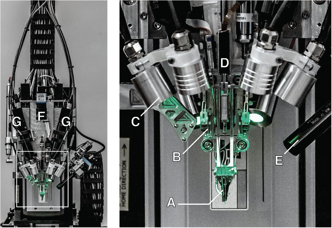
Figure 3 : robotic device for introducing electrodes; an enlarged view of the input head is shown in the inset. A. Loaded needle holder. B. Contact brain position sensor of low impact. C. Light modules with several independent wavelengths. D. Needle motor. E. One of four cameras that focuses on the needle during insertion. F. Camera with a wide viewing angle of the surgical field. G. Stereoscopic cameras.
The head of the robotic device for introducing threads also has a stack of cameras for receiving images (Fig. 3E-G), which are used to guide the needle into the loop of the thread, aim before entering, view the input in real time and check. In addition, the head of the device contains six independent light modules, each of which is capable of independently illuminating with a wavelength of 405 nm, 525 nm and 650 nm or white light (Fig. 3C). Lighting at 405 nm excites fluorescence from polyimide and allows the optical stack and computer vision to reliably localize a 16 × 50 μm2 filament loop and perform submicron visual servo control to direct a 650-nm light-guided needle through the loop. Stereoscopic cameras, software monocular calculations with an extended depth of field and 525 nm light allow you to accurately assess the location of the surface area of the cerebral cortex.
The robot registers locations in a common coordinate grid on the skull, which, combined with depth tracking, accurately targets anatomically defined brain structures. An integrated custom software package allows you to pre-select all insertion points, allowing you to plan the insertion path, minimize confusion and load on each thread. One of the main planning functions is the ability to avoid damage to the vascular network during insertion, which is one of the key advantages of introducing the electrodes separately. This is especially important because it is believed that damage to the blood-brain barrier plays a key role in the inflammatory response of the brain to foreign objects [33].
The robot has an automatic insertion mode, which allows you to insert up to 6 threads (192 electrodes) per minute. Despite the fact that the entire injection procedure can be automated, the surgeon retains full control and, if desired, can perform manual micro-adjustment of the position of the thread before each introduction into the cortex. The neurosurgical robot is compatible with a sterile casing and has features that facilitate successful and quick injections, such as automatic ultrasonic needle sterilization. The needle holder cartridge (NPC; Figure 2C) is the part of the insert head that is in direct contact with brain tissue and is a consumable item that can be replaced during surgery in less than a minute.

Figure 4 : 1. A device for input with a thread approaching the simulation of brain tissue. i. needle and cannula (note: hollow needle). ii. previously inserted thread. 2. The insert touches the surface simulating brain tissue. 3. The needle penetrates the imitation fabric, delivering the thread to a predetermined depth. iii. thread insertion. 4. The thread input device departs, leaving the thread in the fabric. iv. implanted thread.
Using this system, we demonstrated the success of administration in 87.1 ± 12.6% of cases (mean ± standard deviation), after 19 operations. During the study, accurate manual adjustments were made to avoid damage to the microvasculature of the channels on the surface of the cortex, which increased the total time of administration from the fastest. Even with these adjustments, the total administration time for this study averaged ~ 45 minutes, with an approximate rate of administration of 29.6 electrodes per minute (Fig. 6). The introduction was performed with bilateral craniotomy of sites with an area of (4 × 7) mm2 with an interval> 300 μm between filaments in order to maximize cortical coverage. This demonstrates that robotic insertion of thin polymer electrodes is an effective and scalable approach for recording the activity of a large number of neurons in anatomically defined areas of the brain.
4. Electronics
Continuous recording of signals from thousands of electrodes presents significant problems with electronics and packaging. The density of the recording channels requires the placement of a gain module and digitization of the signal in the assembly of the device itself, otherwise the requirements for the cable and connector will be excessively high. This recording module should amplify weak neural signals (<10 μVRMS), at the same time suppress out-of-band noise, sample and digitize amplified signals and output the results for real-time processing - all using the smallest possible power and size.
Electronics is built on our specialized integrated circuit (ASIC) for Neuralink applications, which consists of 256 individually programmable amplifiers (“analog pixels”), built-in analog-to-digital converters (ADCs) and a peripheral control circuit for serializing digitized output signals.
The analog pixel is easily adjustable: the gain and filter properties can be calibrated to account for changes in signal quality due to process variability and the electrophysiological environment. The built-in ADC performs sampling at a frequency of 19.3 kHz with a resolution of 10 bits. Each analog pixel consumes 5.2 μW, and the entire ASIC consumes about 6 mW, including the clock drivers. The characteristics of ASIC Neuralink are shown in Table 1, and a photograph of the manufactured device is shown in Fig. 5A.

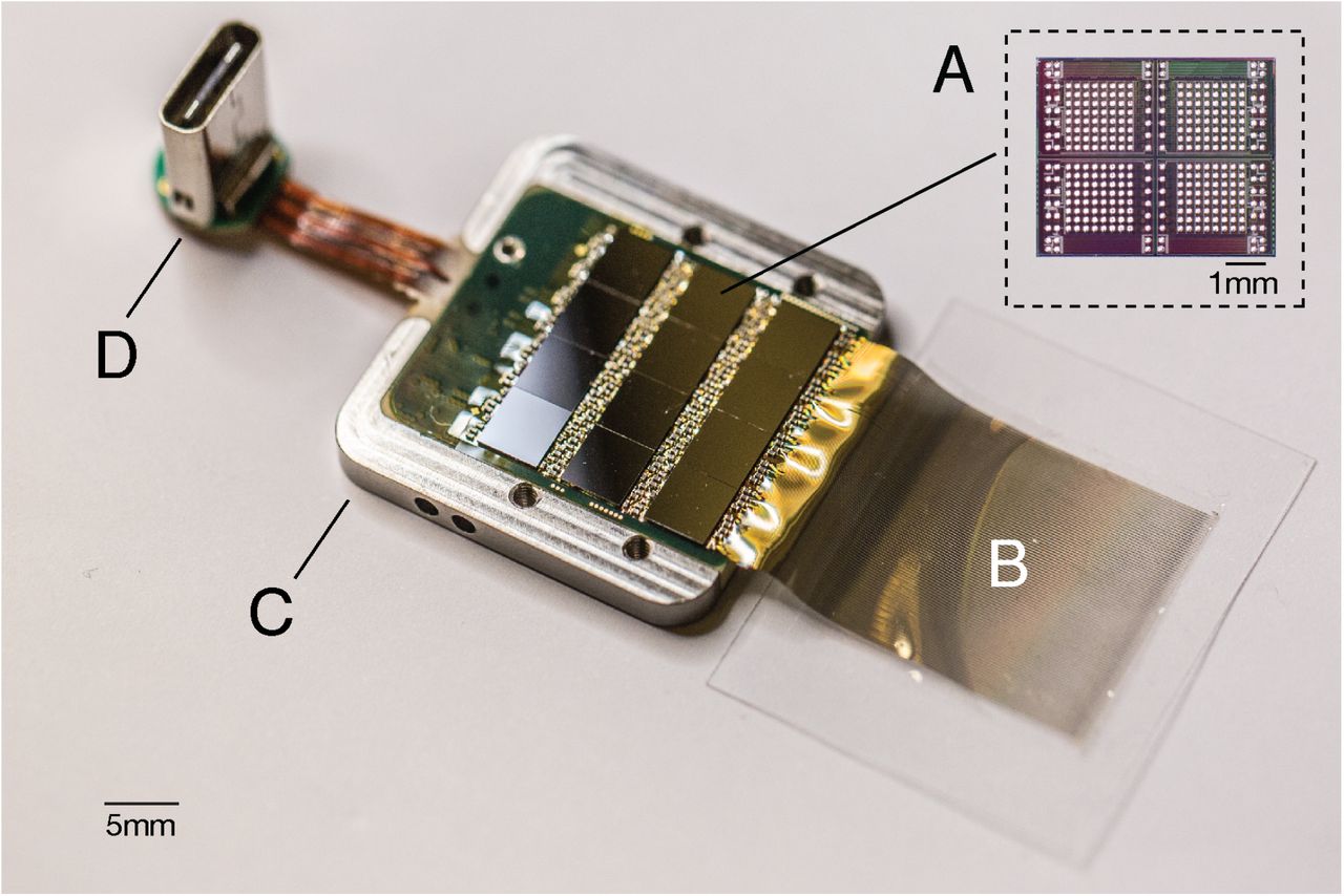
Figure 5 : Touch device in packaging. A. Each individual chip in the ASIC is capable of processing 256 data channels. The entire device assembly contains 12 such chips, which in total is 3072 channels. B. Polymer yarns on a parylene basis. C. Titanium case (cover removed). D. Digital USB-C connector for power and data transfer.
Neuralink ASIC is the core of a modular recording platform that makes it easy to replace components for research and development (Fig. 5). In the systems discussed here, several ASICs are integrated into a standard printed circuit board (PCB) using the flip-chip connection method. Each system consists of a user-programmable gate array (approx. FPGA); temperature sensors, accelerometer, magnetometer in real time and one USB-C connector for data transmission with full bandwidth. The systems are packaged in titanium enclosures that are coated with P-C, which serves as a moisture barrier to prevent liquid from entering and extend service life.
We described the configurations created: the recording system on 1536 channels (System A) and the recording system on 3072 channels (System B), in Table 2. While System A uses the current generation ASIC Neuralink, System B uses the earlier version with comparable functionality, but with lower performance characteristics. System B was designed to maximize channel density and is used for applications that require an extremely large number of channels. System A, by contrast, was designed to provide a faster and more reliable installation; it can be installed five times faster than system B, which is more efficient.


A base station connected to an Ethernet local area network converts data streams from these systems into 10G Ethernet multicast packets that allow subsequent users to process data in various ways, for example, real-time data visualization [34] or recording to disk. Each base station can connect up to three implants simultaneously. The devices are additionally supported by a software ecosystem that provides ease of use on the principle of “plug and play” with zero configuration: the data stream is activated automatically when the cable is connected.
5. Electrophysiology
We implanted both systems A and B to male Long-Evans rats as described in section 3. All animal procedures were performed in accordance with the guidelines of the National Research Council for the Care and Use of Laboratory Animals and were approved by the Neuralink Animal Care and Use Committee. Electrophysiological recordings were made when animals freely explored an arena equipped with a cable that allowed unlimited movement. System A can record 1344 of 1536 channels simultaneously, the exact configuration of the channel can be arbitrarily specified during recording; System B can record from all 3072 channels simultaneously. The digitized broadband signals were processed in real time to determine the action potentials of neurons (peaks) using the online detection algorithm.

Figure 6 : Thread implantation and assembly. A. An example of a live image showing the surface of the cortex with implanted filaments and minimal bleeding. B. Sensor assembly assembly (“System B”), permanently implanted in the rat.
Real-time peak detection requirements for NQFs are different from most traditional neurophysiological studies. While most electrophysiologists take data offline and spend significant effort on rejecting false positive peak events, NQI events should be detected in real time, and peak detection parameters should maximize decoding performance. Using our dedicated online peak detection software, we found that a resolution filter that allows false positives of ± 0.2 Hz is better than setting strict thresholds that can reject real peaks (data not shown).
Given these considerations, we set a threshold at> 0.35 Hz to determine the number of electrodes that recorded peaks. Since we usually don’t sort data by peaks, we don’t report multiple units per channel. BMI decoders usually work without sorting with minimal loss of performance [36, 37]. Moreover, recent results show that peak sorting is not necessary for an accurate assessment of the dynamics of a neural population [38].
The data of a recent experiment using system A are shown in Fig. 7 and fig. 8. In this experiment, 40 out of 44 insertion attempts were successful (90%) for a total of 1280 implanted electrodes, of which 1020 were recorded simultaneously. Broadband signals recorded from the presented filaments show both local potentials and peak activity of Fig. 7. An example of the output of the peak detection system is shown as a raster in Fig. 8. In this example, two overlapping recording configurations were used to record from all 1,280 implanted channels. At this array, our peak yield was 53.4% of the channels, with many peaks appearing at several neighboring channels, as was observed in other experiments with high electrode densities [16, 17, 21]. On other arrays of system A, we obtained a result of 59.10 ± 5.74% (mean ± standard error of the mean) in 19 operations with a maximum of 85.5%.

Figure 7 : Left: Broadband neural signals (unfiltered) simultaneously obtained from a single strand (32 channels) implanted in the rat cerebral cortex. Each channel (row) corresponds to a portion of the electrode on the filament (diagram on the left; sections spaced 50 μm apart). Peaks and local field potentials are obvious. Right: alleged waveforms (unsorted); numbers indicate the location of the channel in the stream. The middle waveform is shown in black.
6. Discussion
We described an NIR with a high number of channels and a single peak resolution. It is based on flexible polymer sensors, a robotic input system and special low-energy electronics. This system serves two main purposes: it is a research platform for use in rodents and serves as a prototype for future human clinical implants.The ability to quickly iterate structures and test rodents allows you to quickly improve devices, production processes and software. Because it is a research platform, the system uses a wired connection to maximize the throughput for streaming raw data. This is important for evaluating performance and is critical for developing signal processing and decoding algorithms. In contrast, the clinical devices that will be manufactured on this platform will be fully implantable, which will require hermetic packaging, and will have built-in signal compression, reduced power consumption, wireless energy transfer and telemetry of data through the skin without using wires.

Figure 8: Our devices allow us to register widespread neural activity, distributed over several areas of the brain and cortical layers. Left: the injection sites (colored circles) are shown on the image of the rodent brain. [35] Right: raster of 1020 simultaneously recorded channels sorted by streams (color corresponds to the insertion point). Sidebar: An enlarged image of peaks from one thread. This thread corresponds to that shown in fig. 7.
Modulation of neural activity will be an important part of the next-generation clinical brain-machine interfaces [39], for example, to provide a sense of touch or proprioception for controlling neuro-prosthetic movements [40, 41]. Therefore, we developed ASIC Neuralink, capable of electrical stimulation on each channel, although we have not demonstrated these capabilities here.
This NQI system has several advantages over previous approaches. The size and composition of thin-film probes are better suited to the properties of brain tissue material than commonly used silicon probes, and therefore may exhibit increased biocompatibility [28, 21]. In addition, the ability to choose where to insert our probes, including into the subcortical structures, allows us to create our own geometries of arrays for targeting certain areas of the brain without damaging the vascular networks. This feature is important for creating a high-performance NKI, since the distribution of the electrodes can be adjusted depending on the requirements of the task. Finally,Neuralink ASIC's miniaturization and design provide great flexibility in system design and support a very high number of channels within a practical size and low power consumption.
Basically, our approach to brain-machine interfaces is extensible and scalable. Here we report on simultaneous broadband recording from more than 3,000 inserted electrodes in a freely moving rat. In a larger brain, several devices with this architecture can be easily implanted, and therefore we could interact with a much larger number of neurons without serious reengineering. Further development of surgical robotics may allow us to achieve this in the same way without significantly increasing the time of surgery.
Before a device with high bandwidth becomes suitable for clinical use, it will be necessary to solve a number of serious technological problems, but now it is easy to imagine that such a device will allow patients with spinal cord injuries to cleverly control a digital mouse and keyboard. And in combination with rapidly improving methods of spinal cord stimulation [42], in the future this approach could restore motor function. High-throughput neural interfaces must provide many new therapeutic options.
7. Acknowledgments
We would like to thank Livermore National Laboratory. Lawrence (LLNL), Berkeley Marvell Nanotechnology Laboratory, Berkeley Wireless Research Center (BWRC), Stanford Nanotechnology Center, and former and current Neuralink employees for their contributions to the work described here.
8. Additional videos
Video 1 : A series of six inserts of a neurosurgical robot in an agarose imitation of brain tissue. The capture of thread by a needle occurs outside the frame. Changes in the background color are caused by lighting at different frequencies of light at different stages of the refueling and insertion process. One thread was inserted before the start of the video. Video .
Video 2 : Three-dimensional visualization of the thread implantation process (same data as in Fig. 8). The thread insert is rendered in the same order as in the real operation, but in the fast playback mode. Thread size and insertion depth are typical. The stereotactic coordinates of each insert are presented in a dataset provided by Calabrese and co-workers [35]. Video .
9. Sources
[1] Leigh R. Hochberg et al. “Neuronal ensemble control of prosthetic devices by a human with tetraplegia”. In: Nature 442 (2006), p. 164. issn: 1476-4687.
[2] Wei Wang et al. “An Electrocorticographic Brain Interface in an Individual with Tetraplegia”. In: PLoS ONE 8 (2013), e55344.
[3] Tyson Aflalo et al. “Decoding motor imagery from the posterior parietal cortex of a tetraplegic human”. In: Science 348 (2015), pp. 906–910. issn: 0036-8075.
[4] Leigh R. Hochberg et al. “Reach and grasp by people with tetraplegia using a neurally controlled robotic arm”. In: Nature 485 (2012), p. 372. issn: 1476-4687.
[5] Jennifer L Collinger et al. “High-performance neuroprosthetic control by an individual with tetraplegia”. In: The Lancet 381 (2013), pp. 557–564. issn: 0140-6736.
[6] Gopala K. Anumanchipalli, Josh Chartier, and Edward F. Chang. “Speech synthesis from neural decoding of spoken sentences”. In: Nature 568 (2019), pp. 493–498. issn: 0028-0836.
[7] György Buzsáki, Costas A. Anastassiou, and Christof Koch. “The origin of extracellular fields and currents — EEG, ECoG, LFP and spikes”. In: Nature Reviews Neuroscience 13 (2012), p. 407. issn: 1471-0048.
[8] Bijan Pesaran et al. “Investigating large-scale brain dynamics using field potential recordings: analysis and interpretation”. In: Nature Neuroscience 21 (2018), pp. 903–919. issn: 1097-6256.
[9] Taro Kaiju et al. “High Spatiotemporal Resolution ECoG Recording of Somatosensory Evoked Potentials with Flexible Micro-Electrode Arrays”. In: Frontiers in Neural Circuits 11 (2017), p. 20.
[10] Rafael Yuste. “From the neuron doctrine to neural networks”. In: Nature Reviews Neuroscience 16 (2015), pp. 487– 497. issn: 1471-003x.
[11] Guosong Hong and Charles M Lieber. “Novel electrode technologies for neural recordings”. In: Nature Reviews Neuroscience (2019), pp. 1–16. issn: 1471-003X.
[12] Edwin M. Maynard, Craig T. Nordhausen, and Richard A. Normann. “The Utah Intracortical Electrode Array: A recording structure for potential brain-computer interfaces”. In: Electroencephalography and Clinical Neurophysiology 102.3 (1997), pp. 228–239. issn: 0013-4694.
[13] Miguel AL Nicolelis et al. “Chronic, multisite, multielectrode recordings in macaque monkeys”. In: Proceedings of the National Academy of Sciences 100.19 (2003), pp. 11041–11046. issn: 0027-8424. eprint: www . pnas.org/content/100/19/11041.full.pdf.
[14] KD Wise et al. “Microelectrodes, Microelectronics, and Implantable Neural Microsystems”. In: Proceedings of the IEEE 96.7 (2008), pp. 1184–1202. issn: 0018-9219.
[15] Nicholas M. Dotson et al. “A Large-Scale Semi-Chronic Microdrive Recording System for Non-Human Primates”. In: Neuron 96 (2017), 769–782.e2. issn: 0896-6273.
[16] James J. Jun et al. “Fully integrated silicon probes for high-density recording of neural activity”. In: Nature 551 (2017), p. 232. issn: 1476-4687.
[17] Gian Nicola Angotzi et al. “SiNAPS: an implantable Active Pixel Sensor CMOS-probe for Simultaneous largescale Neural recordings”. In: Biosensors and Bioelectronics 126 (2018), pp. 355–364. issn: 0956-5663.
[18] Felix Deku et al. “Amorphous silicon carbide ultramicroelectrode arrays for neural stimulation and recording”. In: Journal of Neural Engineering 15.1 (2018), p. 016007.
[19] Aziliz Lecomte, Emeline Descamps, and Christian Bergaud. “A review on mechanical considerations for chronically-implanted neural probes”. In: Journal of Neural Engineering 15 (2018), p. 031001. issn: 1741-2552.
[20] Dion Khodagholy et al. “NeuroGrid: recording action potentials from the surface of the brain”. In: Nature Neuroscience 18 (2014), pp. 310–315. issn: 1097-6256.
[21] Jason E. Chung et al. “High-Density, Long-Lasting, and Multi-region Electrophysiological Recordings Using Polymer Electrode Arrays”. In: Neuron 101 (2019), 21–31.e5. issn: 0896-6273.
[22] Stephan L. Chorover and Anne-Marie Deluca. “A sweet new multiple electrode for chronic single unit recording in moving animals”. In: Physiology & Behavior 9 (1972), pp. 671–674. issn: 0031-9384.
[23] Jia Liu et al. “Syringe-injectable electronics”. In: Nature Nanotechnology 10 (2015), pp. 629–636. issn: 1748-3387.
[24] Tian-Ming Fu et al. “Stable long-term chronic brain mapping at the single-neuron level”. In: Nature Methods 13 (2016), pp. 875–882. issn: 1548-7091.
[25] Flavia Vitale et al. “Fluidic Microactuation of Flexible Electrodes for Neural Recording”. In: Nano Letters 18.1 (2018), pp. 326–335. eprint: doi.org/10.1021/acs.nanolett.7b04184 .
[26] Lan Luan et al. “Ultraflexible nanoelectronic probes form reliable, glial scar–free neural integration”. In: Science Advances 3 (2017), e1601966. issn: 2375-2548.
[27] Marc D. Ferro et al. “NeuroRoots, a bio-inspired, seamless Brain Machine Interface device for long-term recording.” In: bioRxiv (2018), p. 460949.
[28] Timothy L Hanson et al. “The “sewing machine” for minimally invasive neural recording”. In: bioRxiv (2019). eprint: www.biorxiv.org/content/early/2019/03/14/578542.full.pdf .
[29] Kip A Ludwig et al. “Chronic neural recordings using silicon microelectrode arrays electrochemically deposited with a poly(3,4-ethylenedioxythiophene) (PEDOT) film”. In: Journal of Neural Engineering 3 (2006), p. 59. issn: 1741-2552.
[30] Seth J. Wilks et al. “Poly(3,4-ethylenedioxythiophene) as a Micro-Neural Interface Material for Electrostimulation”. In: Frontiers in Neuroengineering 2 (2009), p. 7. issn: 1662-6443.
[31] JD Klein, SL Clauson, and SF Cogan. “Morphology and charge capacity of sputtered iridium oxide films”. In: Journal of Vacuum Science & Technology A: Vacuum, Surfaces, and Films 7 (1989), pp. 3043–3047. issn: 0734- 2101.
[32] SF Cogan, TD Plante, and J. Ehrlich. “Sputtered Iridium Oxide Films (SIROFs) for Low-Impedance Neural Stimulation and Recording Electrodes”. In: The 26th Annual International Conference of the IEEE Engineering in Medicine and Biology Society 2 (2004), pp. 4153–4156.
[33] Tarun Saxena et al. “The impact of chronic blood–brain barrier breach on intracortical electrode function”. In: Biomaterials 34 (2013), pp. 4703–4713. issn: 0142-9612.
[34] Joshua H. Siegle et al. “Open Ephys: an open-source, plugin-based platform for multichannel electrophysiology”. In: J. Neural Eng. 14 (2017), pp. 1–13.
[35] E. Calabrese et al. “A quantitative magnetic resonance histology atlas of postnatal rat brain development with regional estimates of growth and variability”. In: NeuroImage 71 (2013), pp. 196–201.
[36] Sonia Todorova et al. “To sort or not to sort: the impact of spike-sorting on neural decoding performance”. In: Journal of Neural Engineering 11 (2014), p. 056005. issn: 1741-2552.
[37] Breanne P Christie et al. “Comparison of spike sorting and thresholding of voltage waveforms for intracortical brain–machine interface performance”. In: Journal of Neural Engineering 12 (2015), p. 016009. issn: 1741-2552.
[38] Eric M. Trautmann et al. “Accurate Estimation of Neural Population Dynamics without Spike Sorting”. In: Neuron (2019). issn: 0896-6273.
[39] Andy Zhou et al. “A wireless and artefact-free 128-channel neuromodulation device for closed-loop stimulation and recording in non-human primates”. In: Nature Biomedical Engineering 3 (2019), pp. 15–26.
[40] Joseph E O'Doherty et al. “Active tactile exploration using a brain-machine-brain interface”. In: Nature 479 (2011). issn: 1476-4687.
[41] Sharlene N Flesher et al. “Restored tactile sensation improves neuroprosthetic arm control”. In: bioRxiv (2019), p. 653428.
[42] Fabien B. Wagner et al. “Targeted neurotechnology restores walking in humans with spinal cord injury”. In: Nature 563 (2018), pp. 65–71. issn: 0028-0836.
Source: https://habr.com/ru/post/461215/
All Articles