Light control on ZigBee
Hello friends! Today I want to tell you about an interesting development of a remote lighting control system.
A modern house is a huge amount of wires to at least somehow reduce and streamline their number comes to the rescue of the radio. In fact, such a system is not new, but in conditions of limited budget it has fully justified itself.
')
Looking ahead, I want to immediately show the functional diagram of the control system.
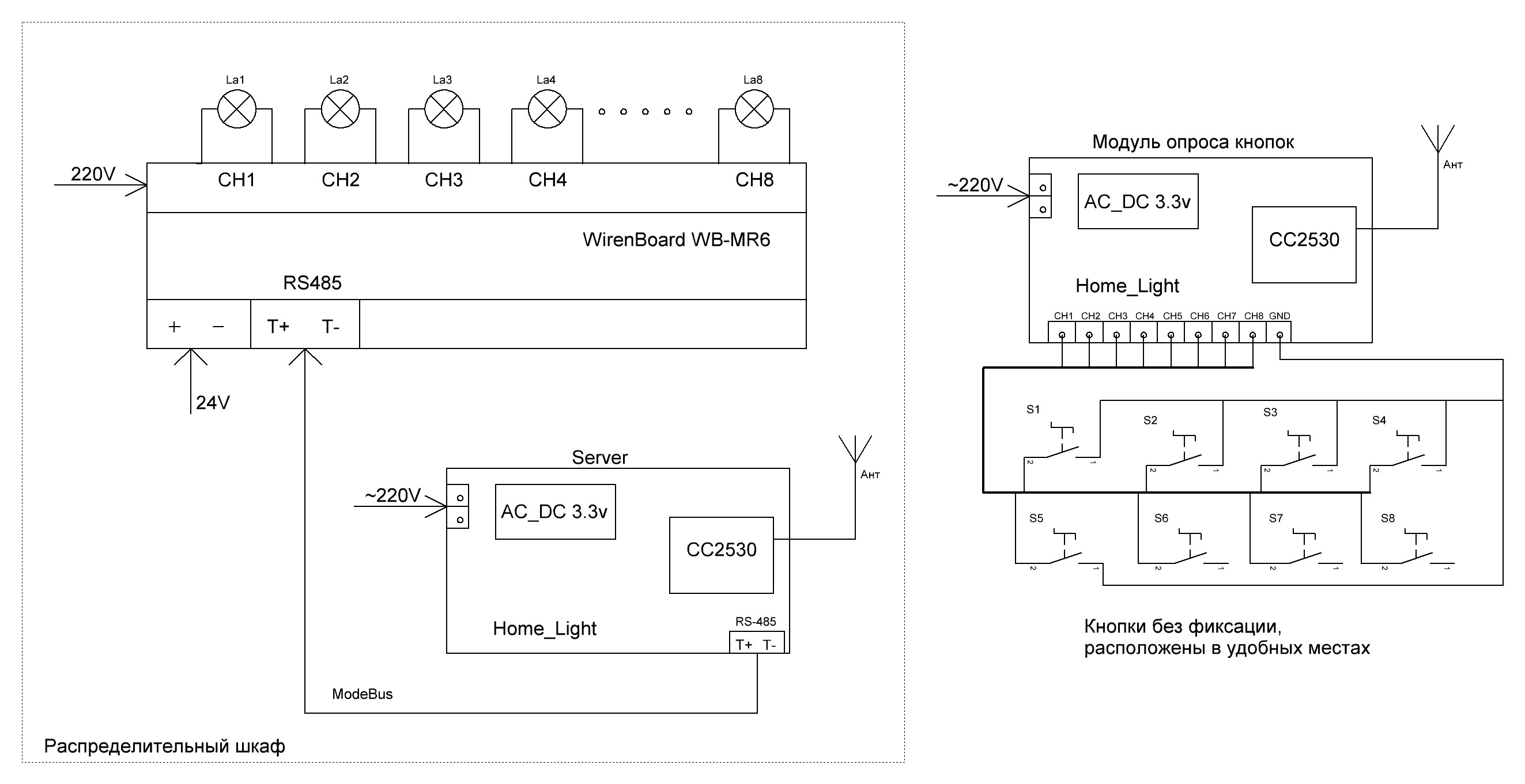
Fig. one
Anyone interested under the cat.
The logical question is why is all this necessary? The use of a wireless light control system gives:
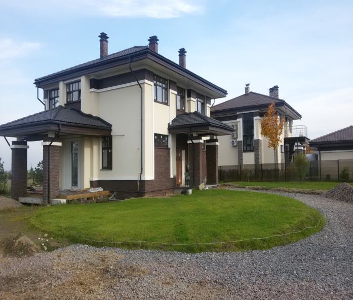
The technical task, at the beginning was just in words and looked very dull and incomprehensible. The point is that in a two-story cottage with an area of 208m.kv, it is necessary to control the on / off of the internal lighting, the system should be powered from 220v to switch 21-23pcs. loads (lamps) with a power not exceeding 200W. At the time of the first inspection of the object, everything looked like this
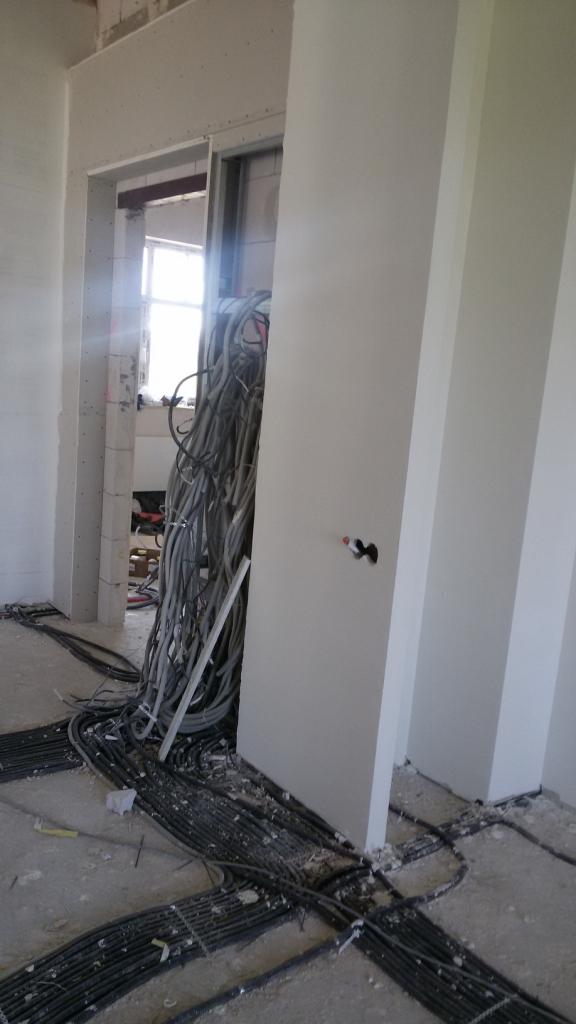
Fig. 2. The main part of communications is laid in the floor then it is all poured with a concrete tie

Fig. 3. Place to install the control cabinet on the second floor
A strong recommendation was to use as few wires as possible. Ideally, only those that are already laid in the floor, walls and ceiling, they go from the installation site of the switchboard to each light bulb. For electromagnetic compatibility of all devices in the house, it was not recommended to use conventional wi-fi. There are countless such devices and the customer has a point in his head that the devices in the house will begin to live their life and the multivarka included will affect the light in the bathroom or toilet. The first thing I did was sketched a structural scheme, as I imagine the solution to this problem. In fig_4 this option.
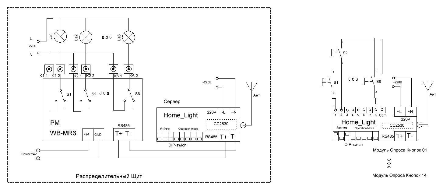
Fig. 4. Functional scheme of lighting control.
The basis was taken from the Texas Instruments CC2530 radio module which supports ZiegBee technology and is quite simply programmed in C ++ with the help of IAR-studio 5.5. Directly switching loads is performed using relay modules WB-MR6 (wirenboard) I chose this element, because in a compact package on a din-rail, six relays with non-dependent channels are installed, the 16A control takes into account all the features of switching general-purpose power loads in tons. h with large starting currents: control of LED lights, incandescent lamps, pulsed power supplies. Plus, each relay contact is surge protected by a varistor. It was necessary to install six of such modules in order to calmly manage the specified number of loads. All WB-MR6 are connected via ModBus interface into a single network. Each relay module is set to the address corresponding to the wiring diagram and the whole system with input pads, fuses, circuit breakers is rather tightly mounted in two distribution boxes ShchMP2-1 500x400x150. For the compact placement of 46 input cables 3x1.5 (single-core copper) had to change the traditional position of the din-rails on the vertical.
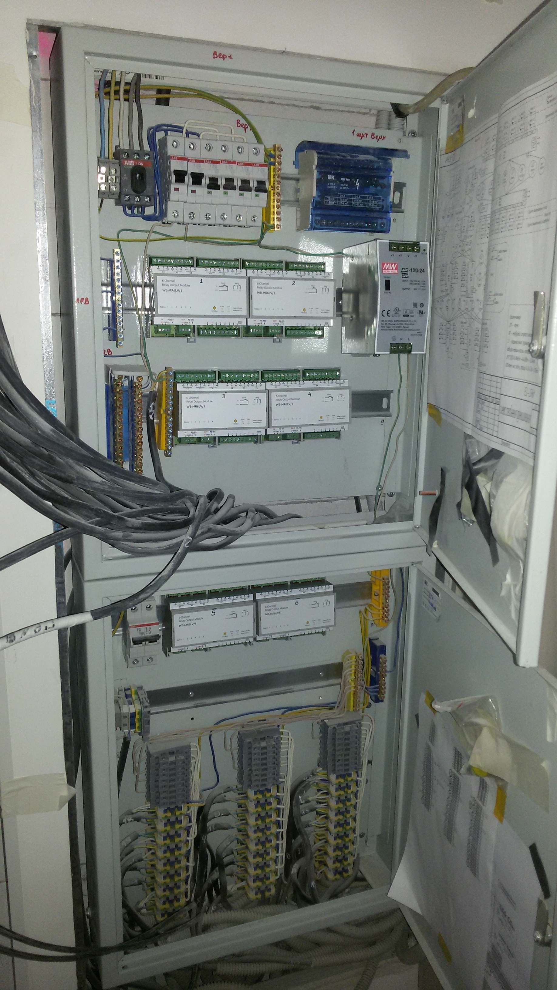
Fig. 5. Switchboard with the placement of lighting control devices.
It should be noted that the incredibly useful function of the WB-MR6 was the ability to control the relay outputs by simply connecting normally open buttons to the bottom terminal block, for a temporary wiring diagram, this is what you need. T.K. control by ModBus appeared five months later, after the assembly and installation of switchboards. During this time, all cables going to each load were completely checked and numbered. And a detailed switching scheme was drawn up, with the switch control logic - a light bulb in fig_6.
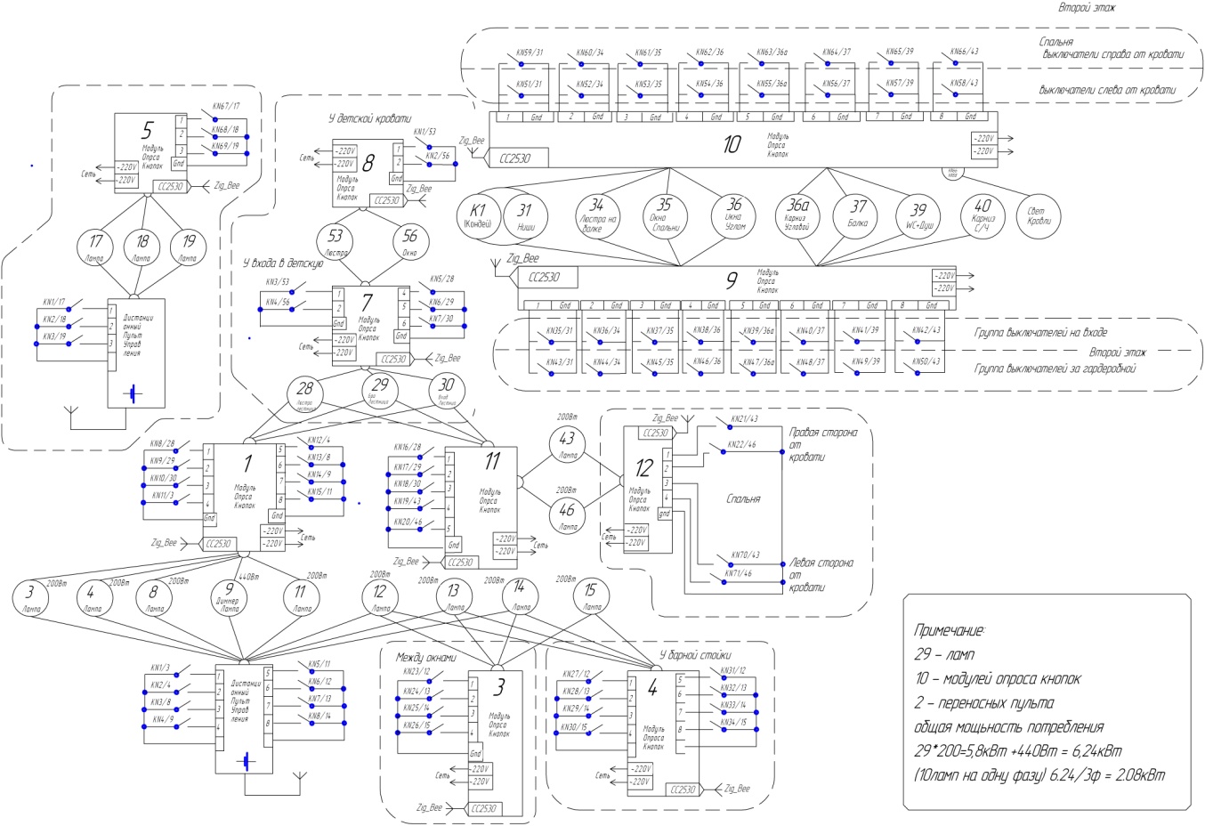
Fig. 6. Scheme of lighting control and placement of loads and survey modules.
According to the survey modules, I can say the following: the functional diagram shown in fig_7 turned out to be quite efficient. Almost nothing had to be redone, the radio frequency module ss2530 allows you to assign any inputs to any outputs. The only exception is UART (pin20-Tx, pin21-Rx). Most of the list of items was bought on “Ali.” Printed circuit boards were ordered in “resonate”. They soldered all twenty pieces with their hands, but it was hard, it took a week to complete, not everything at once turned out need to. But gained invaluable experience mounting SMD components.
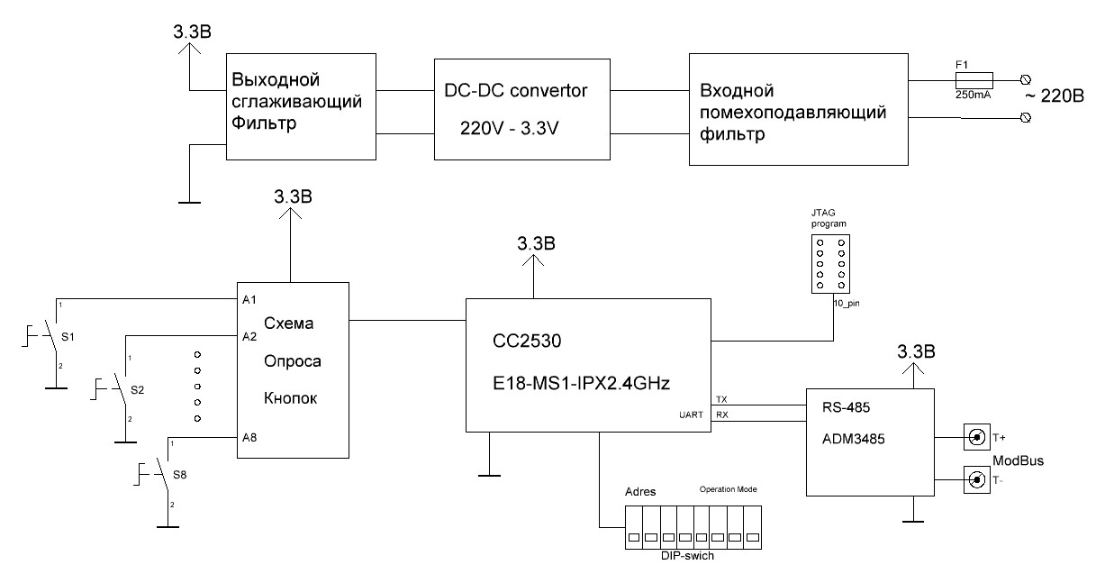
Fig. 7. Functional diagram of the button poll module
The process of debugging the system and bringing it into a fully operational state took a little more than three months. The first steps after assembling the boards of fig_8, checking on the power supply and connecting to the programmer, were writing a program for polling the buttons and generating control commands for the WB-MR6 relay modules via the ModBus bus.
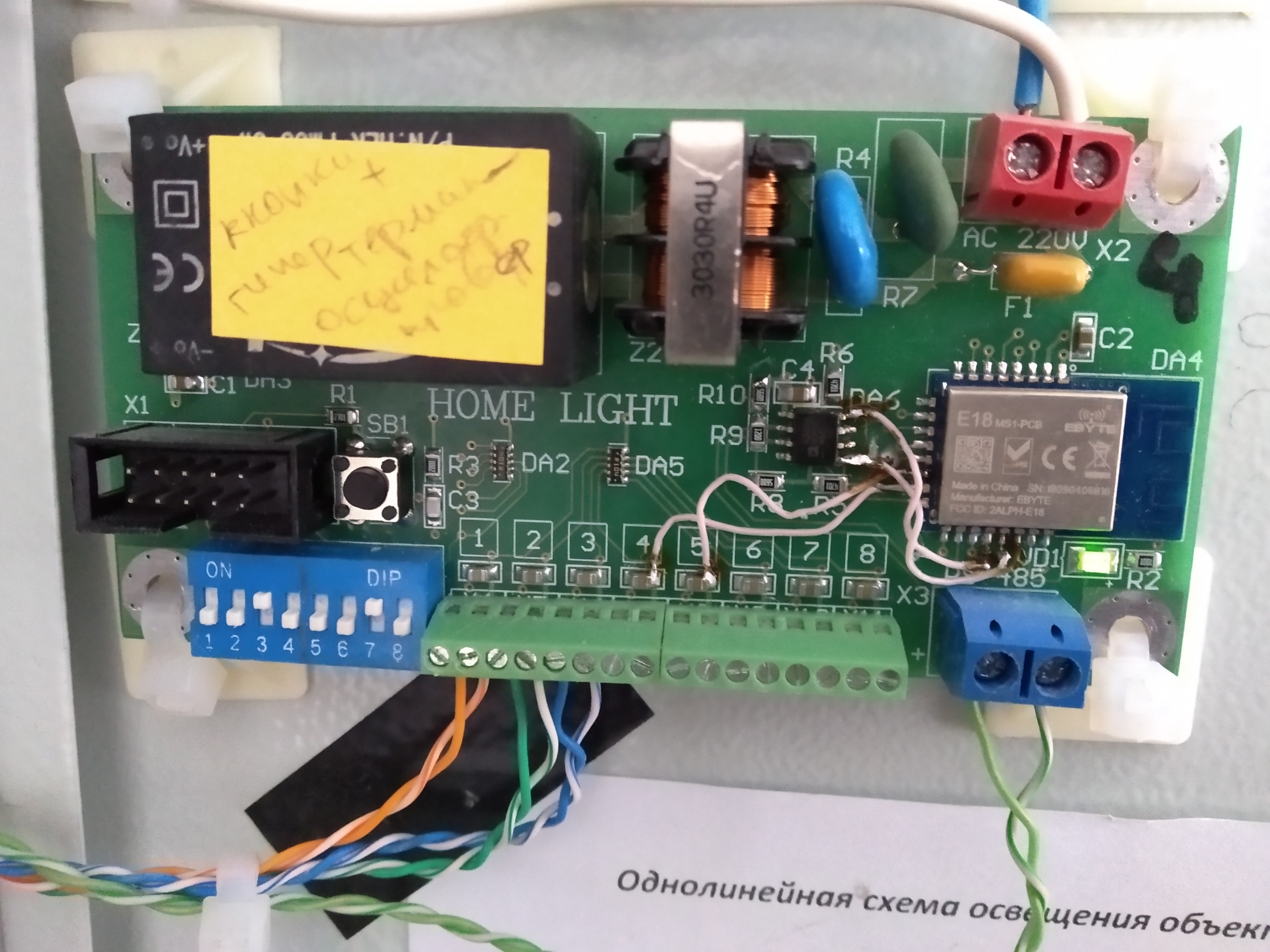
Fig. 8. Button polling module
It was pretty quick and easy. One relay button module without a network interface is connected to one relay module via RS485. Immediately managed to apply the resulting success on the object Fig_9, twisted pair UTP, from the buttons located in the bedroom, was laid in advance. With the mounting of the modules, he didn’t particularly wisely, the self-adhesive platforms and plastic clamps help a lot.
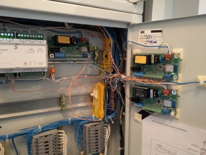
Fig. 9. Fastening modules for polling buttons.
Next, programmatically added an address to each module that was set using the dip switch and the corresponding switching card for the master / slave mode of operation and transmission of commands via radio. The step in front was serious and therefore there were a lot of difficulties in debugging. The most serious is the transfer of information about the pressed button to the master module connected to the Modbus bus as soon as the zig-bee data transfer protocol was activated, everything turned out to be several times more complicated. For those who read up here, I can say that the problem was that the timers in the processor core work unpredictably, more precisely in the IAR compiler, you need to constantly specify its settings when you call the time counting procedure. To find a way to solve this problem, the functions of monitoring and control of data transmitted by radio were added. The control of the button press in the service mode was instantly displayed in the hyper-terminal of the computer that is connected via the RS485-USB adapter to the polling module. Another serious problem with the organization of the lighting control network was the insufficient range of the radio interface. More or less, surely everything was switched only within the table on which the model was assembled. This is a consequence of the features of the energy-saving mode of the CC2530, its default function is to reduce the radiation power, after the formation of the link, I don’t know why, but it was found through jtag in the step-by-step debugging mode. After turning off this mode, the network began to work within only one floor in the cottage; in fact, the commands for turning on / off the lights were processed by the server, only from the polling modules located within 12-14m. Provided that there were no walls. To solve this problem, the replacement path of the CC2530 module with a planar antenna was chosen to the module with an external antenna (with the IPEX connector), all the more so as we managed to successfully buy three modules in the E18-MSI-IPX plus version of the antenna and cable in one of the St. Petersburg online stores. All this was quickly soldered, the angles for fixing the antennas were made and screwed to the transition plates Fig_10.
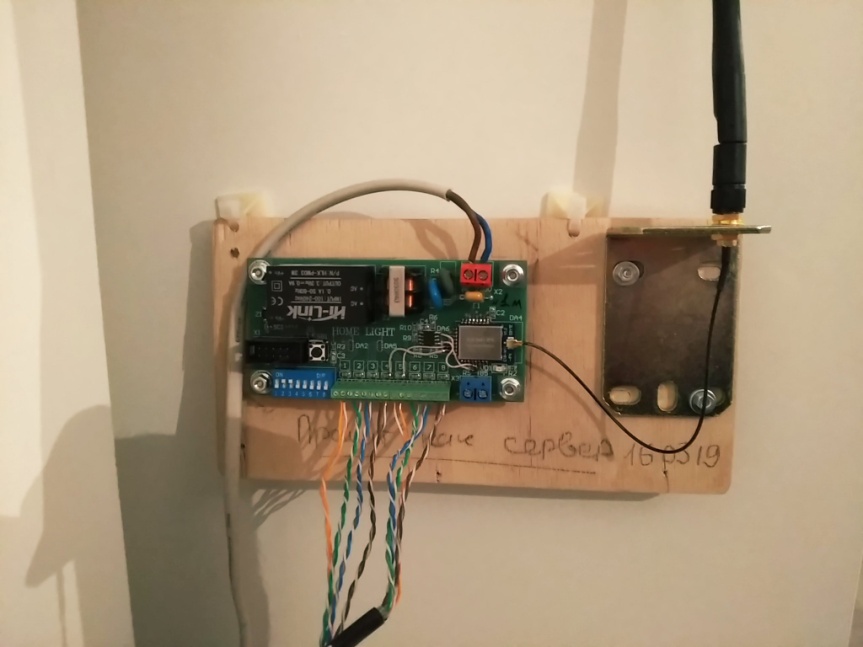
Fig. 10. Using an external antenna
The result of such an obgreyda rather puzzled me - because the range has not changed much, I would even say that it has slightly decreased. I began to look for a way out of this situation in optimizing the algorithms of the program, the initial settings of the CC2530 had to be re-read the car of the datasheets and forums on this topic. The goal was to make each module on the network work as a repeater, especially since this feature is enabled by default and is supported by any device using the Zig-Bee protocol. But in my case it was not obvious. As a result, I decided to introduce an additional module into the system, which would have a unique firmware activated by raising only pin_6 on the dip switch. He had to, was on the ceiling of the first floor and simply broadcast the accepted commands, i.e. be a signal booster.
I have to say, it was a dead end. But during the implementation of this idea, I accidentally measured the parameters of the “black” antenna, which I was sold in an online store with a CC2530 and a cable. The network analyzer showed a CWS 1.9 at a frequency of 2.4 GHz - comments are unnecessary, you need to make your antenna. A request to the search engine immediately gives the correct answer, the antenna "Clover" and detailed instructions for manufacturing.
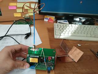
Fig. 11. Antenna and device for its manufacture.
Literally in the evening I made three pieces of these antennas, checked them with a CWS of no worse than 1.2. I can not say about the other characteristics, radiation pattern and gain. But the fact is that the range of confident reception and sending commands has doubled. Pic_12

Fig. 12. Measurement of antenna parameters
As a result, it was possible to achieve a normal reception of the server signal on all 12 polling modules installed in the cottage. So the requirement of the TZ is completely fulfilled in time; I almost met the set deadlines. Customer satisfied.
A modern house is a huge amount of wires to at least somehow reduce and streamline their number comes to the rescue of the radio. In fact, such a system is not new, but in conditions of limited budget it has fully justified itself.
')
Looking ahead, I want to immediately show the functional diagram of the control system.
Fig. one
Anyone interested under the cat.
The logical question is why is all this necessary? The use of a wireless light control system gives:
- Reducing the number of wires from each switch to the junction box in the room.
- The possibility of implementing pass-through switches.
- Flexibility to control any load from any switch as well as the use of normally closed normally open buttons.
- The ability to implement any temporary shutter speeds on / off.
The technical task, at the beginning was just in words and looked very dull and incomprehensible. The point is that in a two-story cottage with an area of 208m.kv, it is necessary to control the on / off of the internal lighting, the system should be powered from 220v to switch 21-23pcs. loads (lamps) with a power not exceeding 200W. At the time of the first inspection of the object, everything looked like this
Fig. 2. The main part of communications is laid in the floor then it is all poured with a concrete tie
Fig. 3. Place to install the control cabinet on the second floor
A strong recommendation was to use as few wires as possible. Ideally, only those that are already laid in the floor, walls and ceiling, they go from the installation site of the switchboard to each light bulb. For electromagnetic compatibility of all devices in the house, it was not recommended to use conventional wi-fi. There are countless such devices and the customer has a point in his head that the devices in the house will begin to live their life and the multivarka included will affect the light in the bathroom or toilet. The first thing I did was sketched a structural scheme, as I imagine the solution to this problem. In fig_4 this option.
Fig. 4. Functional scheme of lighting control.
The basis was taken from the Texas Instruments CC2530 radio module which supports ZiegBee technology and is quite simply programmed in C ++ with the help of IAR-studio 5.5. Directly switching loads is performed using relay modules WB-MR6 (wirenboard) I chose this element, because in a compact package on a din-rail, six relays with non-dependent channels are installed, the 16A control takes into account all the features of switching general-purpose power loads in tons. h with large starting currents: control of LED lights, incandescent lamps, pulsed power supplies. Plus, each relay contact is surge protected by a varistor. It was necessary to install six of such modules in order to calmly manage the specified number of loads. All WB-MR6 are connected via ModBus interface into a single network. Each relay module is set to the address corresponding to the wiring diagram and the whole system with input pads, fuses, circuit breakers is rather tightly mounted in two distribution boxes ShchMP2-1 500x400x150. For the compact placement of 46 input cables 3x1.5 (single-core copper) had to change the traditional position of the din-rails on the vertical.
Fig. 5. Switchboard with the placement of lighting control devices.
It should be noted that the incredibly useful function of the WB-MR6 was the ability to control the relay outputs by simply connecting normally open buttons to the bottom terminal block, for a temporary wiring diagram, this is what you need. T.K. control by ModBus appeared five months later, after the assembly and installation of switchboards. During this time, all cables going to each load were completely checked and numbered. And a detailed switching scheme was drawn up, with the switch control logic - a light bulb in fig_6.
Fig. 6. Scheme of lighting control and placement of loads and survey modules.
According to the survey modules, I can say the following: the functional diagram shown in fig_7 turned out to be quite efficient. Almost nothing had to be redone, the radio frequency module ss2530 allows you to assign any inputs to any outputs. The only exception is UART (pin20-Tx, pin21-Rx). Most of the list of items was bought on “Ali.” Printed circuit boards were ordered in “resonate”. They soldered all twenty pieces with their hands, but it was hard, it took a week to complete, not everything at once turned out need to. But gained invaluable experience mounting SMD components.
Fig. 7. Functional diagram of the button poll module
The process of debugging the system and bringing it into a fully operational state took a little more than three months. The first steps after assembling the boards of fig_8, checking on the power supply and connecting to the programmer, were writing a program for polling the buttons and generating control commands for the WB-MR6 relay modules via the ModBus bus.
Fig. 8. Button polling module
It was pretty quick and easy. One relay button module without a network interface is connected to one relay module via RS485. Immediately managed to apply the resulting success on the object Fig_9, twisted pair UTP, from the buttons located in the bedroom, was laid in advance. With the mounting of the modules, he didn’t particularly wisely, the self-adhesive platforms and plastic clamps help a lot.
Fig. 9. Fastening modules for polling buttons.
Next, programmatically added an address to each module that was set using the dip switch and the corresponding switching card for the master / slave mode of operation and transmission of commands via radio. The step in front was serious and therefore there were a lot of difficulties in debugging. The most serious is the transfer of information about the pressed button to the master module connected to the Modbus bus as soon as the zig-bee data transfer protocol was activated, everything turned out to be several times more complicated. For those who read up here, I can say that the problem was that the timers in the processor core work unpredictably, more precisely in the IAR compiler, you need to constantly specify its settings when you call the time counting procedure. To find a way to solve this problem, the functions of monitoring and control of data transmitted by radio were added. The control of the button press in the service mode was instantly displayed in the hyper-terminal of the computer that is connected via the RS485-USB adapter to the polling module. Another serious problem with the organization of the lighting control network was the insufficient range of the radio interface. More or less, surely everything was switched only within the table on which the model was assembled. This is a consequence of the features of the energy-saving mode of the CC2530, its default function is to reduce the radiation power, after the formation of the link, I don’t know why, but it was found through jtag in the step-by-step debugging mode. After turning off this mode, the network began to work within only one floor in the cottage; in fact, the commands for turning on / off the lights were processed by the server, only from the polling modules located within 12-14m. Provided that there were no walls. To solve this problem, the replacement path of the CC2530 module with a planar antenna was chosen to the module with an external antenna (with the IPEX connector), all the more so as we managed to successfully buy three modules in the E18-MSI-IPX plus version of the antenna and cable in one of the St. Petersburg online stores. All this was quickly soldered, the angles for fixing the antennas were made and screwed to the transition plates Fig_10.
Fig. 10. Using an external antenna
The result of such an obgreyda rather puzzled me - because the range has not changed much, I would even say that it has slightly decreased. I began to look for a way out of this situation in optimizing the algorithms of the program, the initial settings of the CC2530 had to be re-read the car of the datasheets and forums on this topic. The goal was to make each module on the network work as a repeater, especially since this feature is enabled by default and is supported by any device using the Zig-Bee protocol. But in my case it was not obvious. As a result, I decided to introduce an additional module into the system, which would have a unique firmware activated by raising only pin_6 on the dip switch. He had to, was on the ceiling of the first floor and simply broadcast the accepted commands, i.e. be a signal booster.
I have to say, it was a dead end. But during the implementation of this idea, I accidentally measured the parameters of the “black” antenna, which I was sold in an online store with a CC2530 and a cable. The network analyzer showed a CWS 1.9 at a frequency of 2.4 GHz - comments are unnecessary, you need to make your antenna. A request to the search engine immediately gives the correct answer, the antenna "Clover" and detailed instructions for manufacturing.
Fig. 11. Antenna and device for its manufacture.
Literally in the evening I made three pieces of these antennas, checked them with a CWS of no worse than 1.2. I can not say about the other characteristics, radiation pattern and gain. But the fact is that the range of confident reception and sending commands has doubled. Pic_12
Fig. 12. Measurement of antenna parameters
As a result, it was possible to achieve a normal reception of the server signal on all 12 polling modules installed in the cottage. So the requirement of the TZ is completely fulfilled in time; I almost met the set deadlines. Customer satisfied.
Source: https://habr.com/ru/post/460637/
All Articles