Details of the implementation of RSTP and proprietary Extended Ring Redundancy
On the net you can find a lot of materials about the RSTP protocol. In this article, I propose to compare the RSTP protocol with the proprietary protocol from Phoenix Contact - Extended Ring Redundancy.
RSTP implementation details
General information
')
Convergence time - 1-10 s
Possible topologies - any
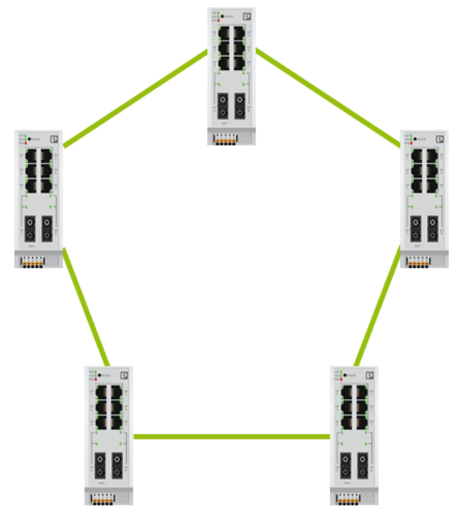
It is widely believed that RSTP allows you to combine switches only in a ring:
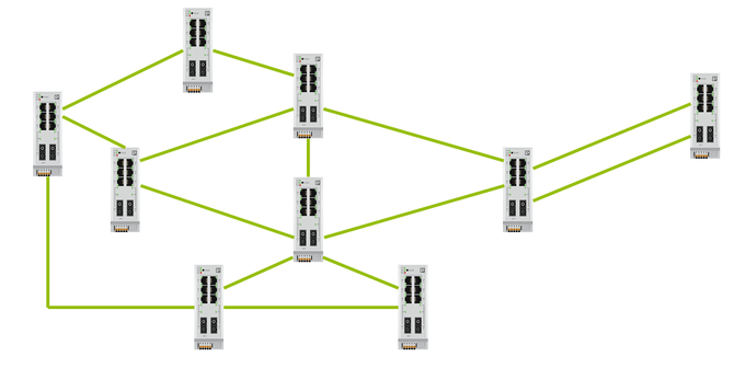
But RSTP allows you to connect switches in an arbitrary way. For example, RSTP can handle this topology.
Operating principle
RSTP reduces any topology to a tree. One of the switches becomes the center of the topology - the root switch. The root switch passes the largest amount of data through itself.
The principle of operation of RSTP is as follows:
Choosing a root switch
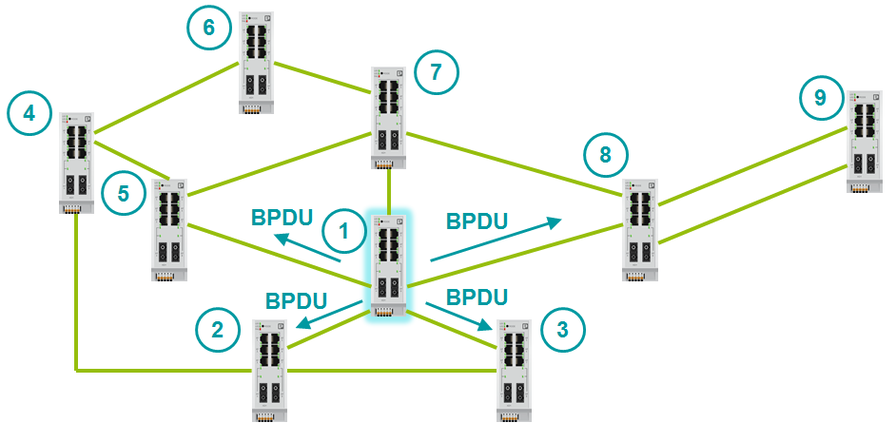
Switches with RSTP exchange BPDU packets. BPDU is a service packet that contains RSTP information. BPDUs are of two types:
Configuration BPDU is used to build the topology. It is sent only by the root switch. Configuration BPDU contains:
Topology Change Notification can send any switch. They are sent in case of a change in topology.
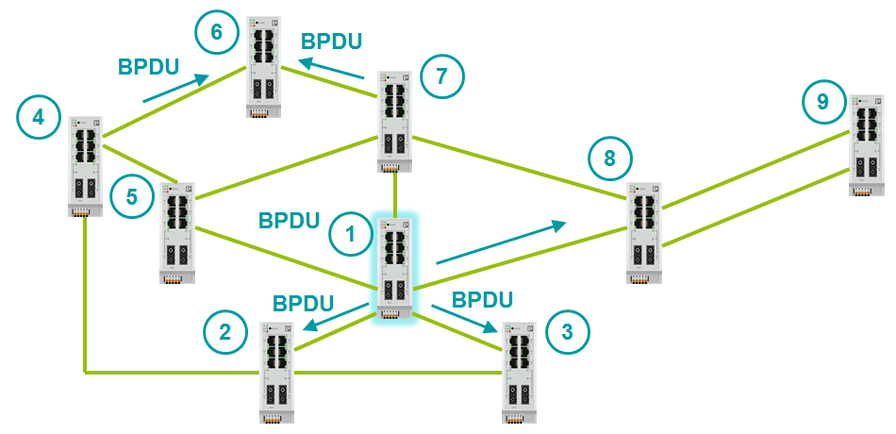
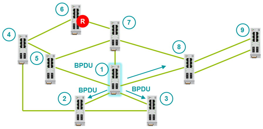
After switching on, all switches consider themselves root. They begin to send BPDU packets. As soon as the switch receives a BPDU with a smaller Bridge ID than its own, it will no longer consider itself root.
Bridge ID consists of two values - the MAC address and Bridge Priority. We cannot change the MAC address. Bridge Priority defaults to 32768. If you do not change Bridge Priority, the switch with the lowest MAC address becomes the root switch. The switch with the lowest MAC address is the oldest and possibly not the most efficient. It is recommended that you manually identify the root switch topology. To do this, you need to configure a small Bridge Priority on the root switch (for example, 0). You can also define a backup root switch by giving it a slightly larger Bridge Priority (for example, 4096).
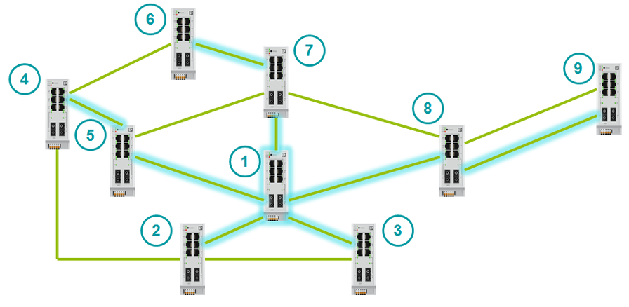
Choosing the path to the root switch
The root switch sends BPDU packets to all active ports. BPDU has a Path Cost field. Path Cost denotes the cost of the path. The higher the cost of the path, the longer the packet is transmitted through it. When BPDU passes through a port, a cost is added to the Path Cost field. The added number is called Port Cost.
Adds a specific value to Path Cost when a BPDU passes through a port. That value that adds is called Port Cost (Port Cost) and can be determined both manually and automatically. Port Cost can be determined either manually or automatically.
When a non-root switch has several alternative paths to the root, it chooses the fastest one. He compares the path cost of these paths. The port from which the BPDU came with the lowest Path Cost becomes the root (Root Port).
The cost of ports that are assigned automatically can be viewed in the table:
Roles and statuses of ports
Switch ports have several statuses and port roles.
Port statuses (for STP):
STP convergence time - 30-50 seconds. After switching on the switch, all ports go through all statuses. Each status port is a few seconds. Because of this principle, STP has such a long convergence time. RSTP has fewer port statuses.
Port statuses (for RSTP):
Port Roles:
The selection of Root Port is described above. How is Designated port selected?
First, let's define what a LAN segment is. The LAN segment is a collision domain. For a switch or router, each port forms a separate collision domain. A LAN segment is a channel between switches or routers. If we talk about the hub, then at the hub all the ports are in the same collision domain.
Only one Designated Port is assigned to one segment.
In the case of segments where there are already Root Portes, everything is clear. The second port of the segment becomes the Designated Port.
But there are backup channels where there will be one Designated Port and one Alternate Port. How will they get out? Designated Port will become the port with the lowest Path Cost to the root switch. If Path Cost is equal, then Designated Port will be the port that is located on the switch with the lowest Bridge ID. If the Bridge ID is equal, then the Designated Port becomes the port with the lowest number. The second port will be alternate.
The last moment remains: when is the port assigned to the Backup role? As already stated above, the Backup port is used only when two channels of the switch are connected to the same segment, that is, to the hub. In this case, the Designated Port is selected exactly according to the same criteria:
Maximum number of devices on the network
The IEEE 802.1D standard does not impose strict requirements on the number of devices on a LAN with RSTP. But the standard recommends using no more than 7 switches in one branch (no more than 7 hops), i.e. no more than 15 in the ring. When this value is exceeded, the time of network convergence begins to increase.
ERR implementation details.
General information
Convergence time
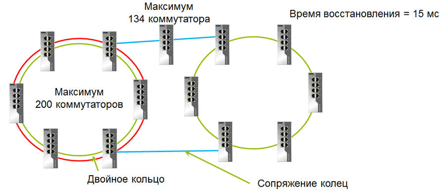
ERR convergence time is 15 ms. With the maximum number of switches in the ring and the presence of pairing rings - 18 ms.
Possible topologies
ERR does not allow to freely merge devices as RSTP. ERR has clear topologies that can be used:
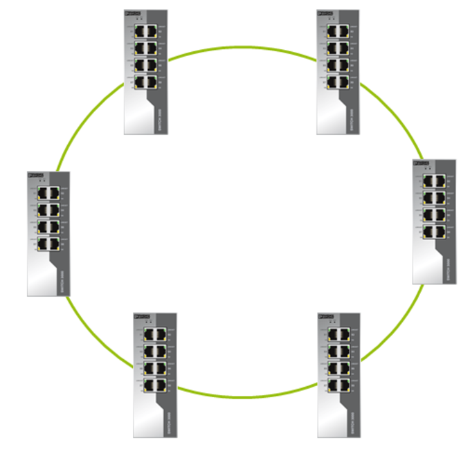
Ring
When all switches are combined into one ring in ERR, then on each switch you need to configure the ports that will be involved in building the ring.
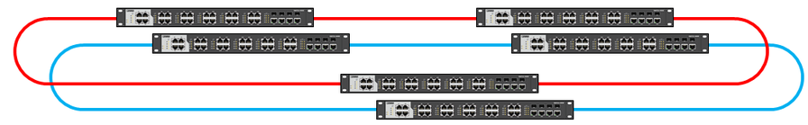
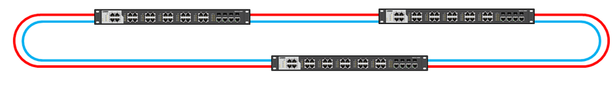
Double ring
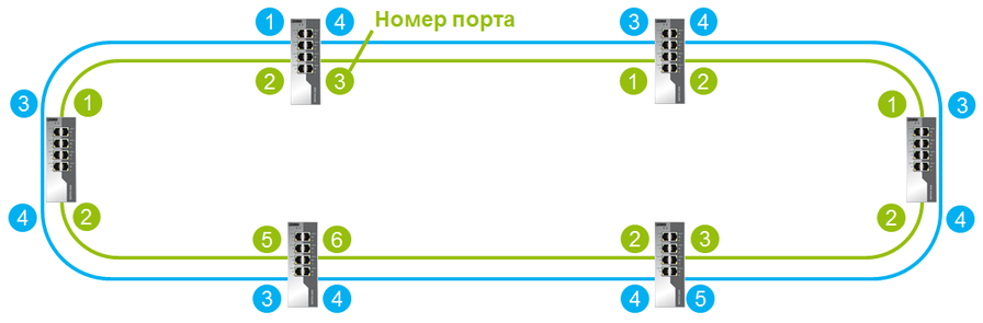
Switches can be combined into a double ring, which greatly increases the reliability of the ring.
Double Ring Restrictions:
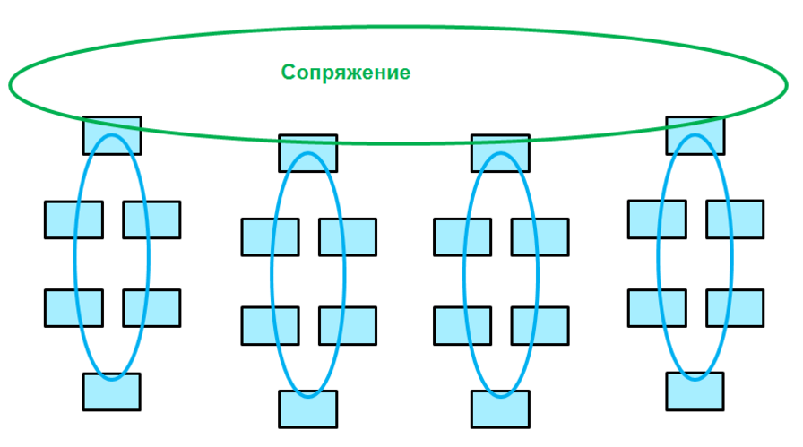
Pairing rings
When pairing in the network can be no more than 200 devices.
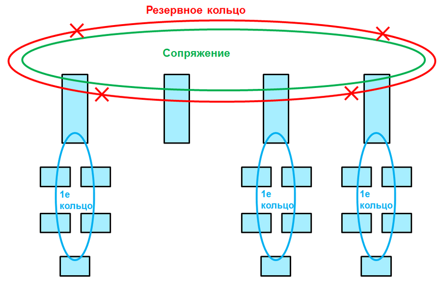
Pairing rings means combining the remaining rings into another ring.
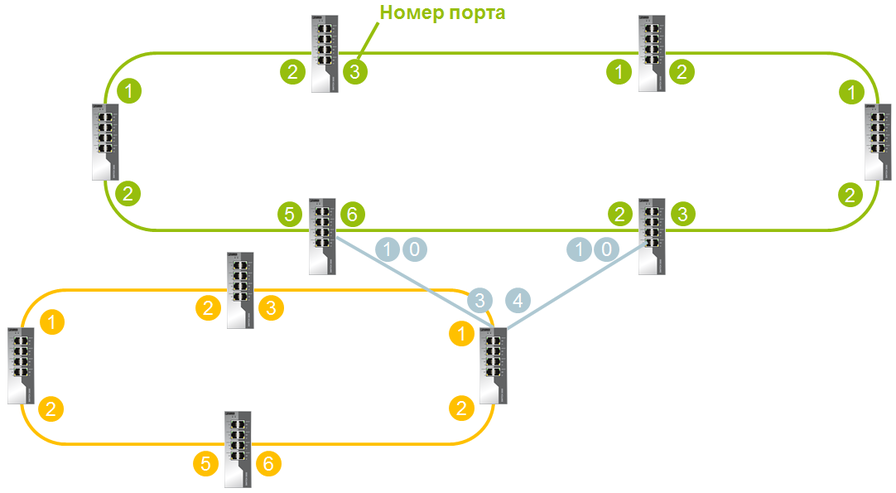
If a ring connects to a pairing ring through a single switch, this is called pairing rings through a single switch . If two switches from a local ring are connected to a pairing ring, this will be a pairing through two switches .
When pairing through one switch on the device, both ports are enabled. The convergence time in this case will be approximately 15-17 ms. With such a pairing, the pairing switch will be a point of failure, since having lost this switch, the whole ring is lost at once. Pairing through two switches avoids this.
It is possible to match duplicated rings.

Path control
The Path Control function allows you to configure the ports through which data will be transmitted in the normal mode of operation. If the channel fails and the network is rebuilt to the backup topology, then after the restoration of the channel, the network will be rebuilt back to the specified topology.
This feature saves redundant cable. Moreover, the topology used for troubleshooting will always be known.
The basic topology switches to the backup in 15 ms. Re-switching when restoring the network will take about 30 ms.
Limitations:
Operating principle

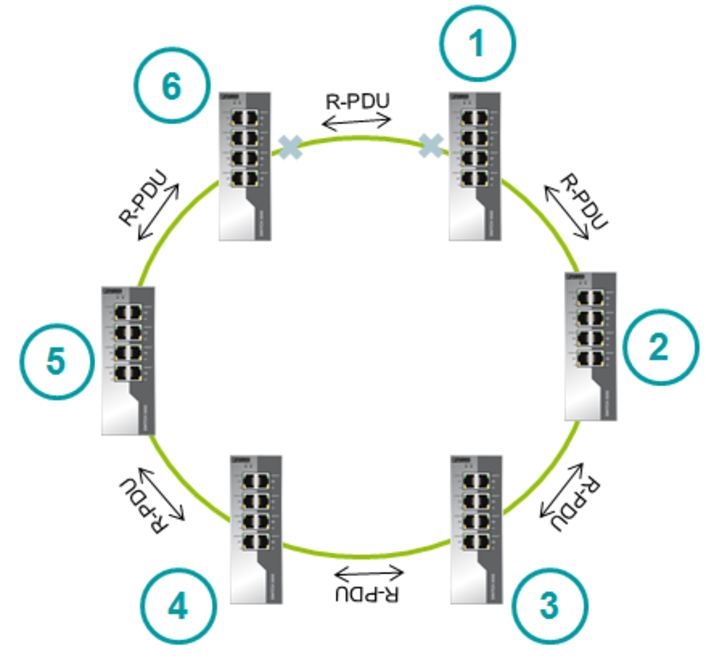
ERR principle of operation
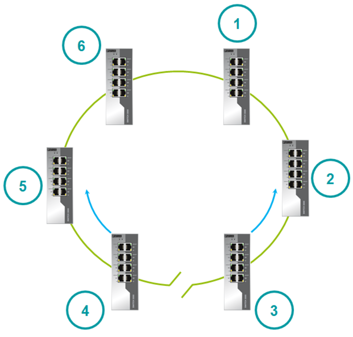
For example, consider the six switches - 1-6. Switches are united in a ring. Each switch uses two ports to connect to the ring and stores their status. Switches send port status to each other. These device data are used to set the initial state of the ports.
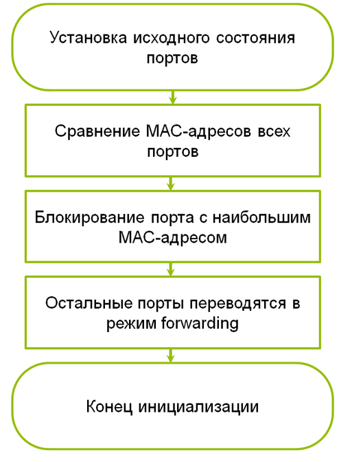
Ports have only two roles - Blocked and Forwarding .
The switch with the highest MAC address blocks the port. All other ports in the ring transmit data.
If the Blocked port stops working, then the next port with the highest MAC address becomes Blocked.
After booting, switches begin to send Ring Protocol Data Unit (R-PDU). R-PDU is transmitted using multicast. The R-PDU is a service message, as is the BPDU in RSTP. The R-PDU contains the switch port statuses and its MAC address.
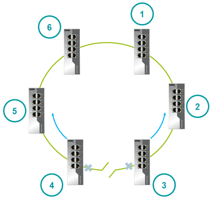
Algorithm of actions in case of channel failure
When the link fails, the switches send an R-PDU to notify you of the port status change.
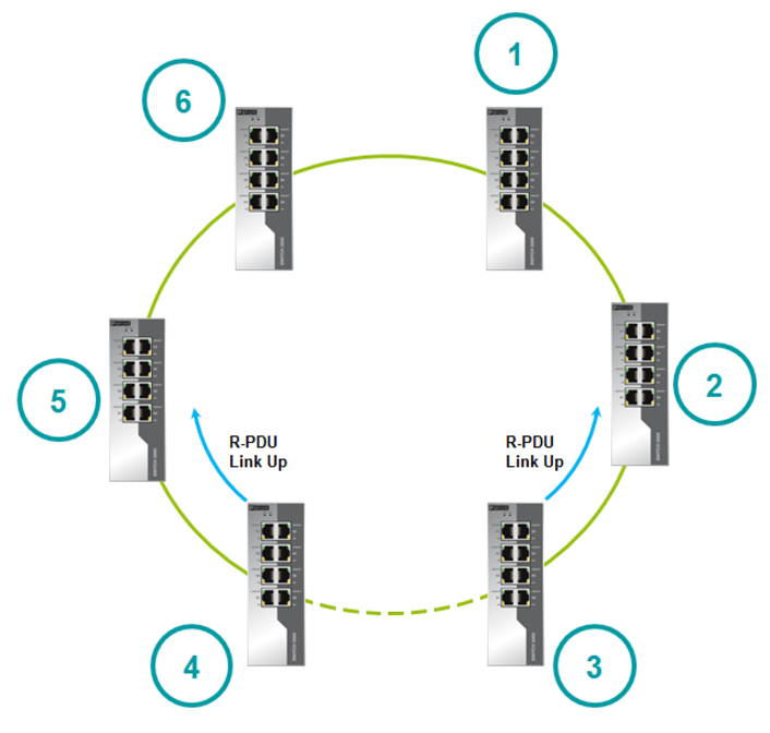
Algorithm of actions during the restoration of the channel
When the failed link is brought into service, the switches send an R-PDU to notify you of the port status change.
The switch with the highest MAC address becomes the new root switch.
The failed channel becomes backup.
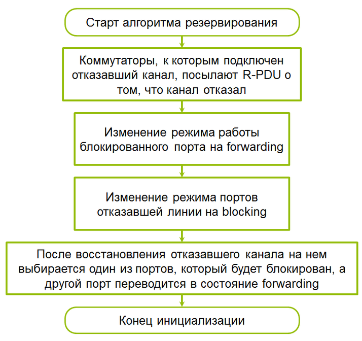
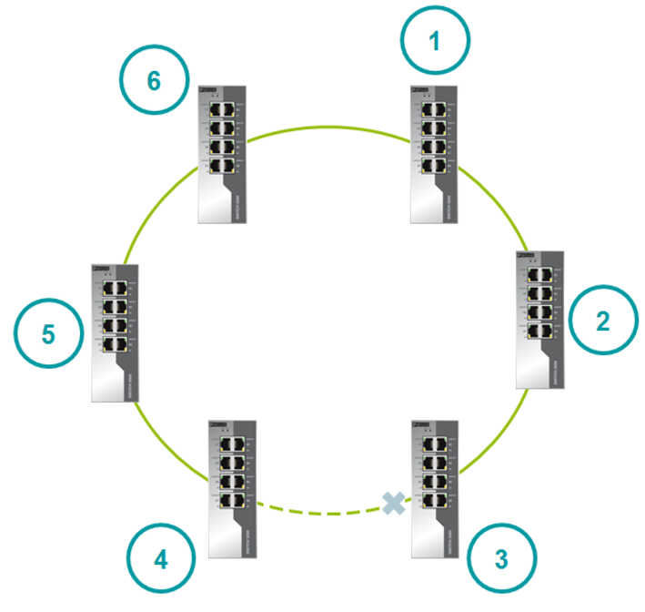
After recovery, one of the channel ports remains blocked, and the second is transferred to the forwarding state. A blocked port becomes the port with the highest speed. If the speeds are equal, then the switch port with the highest MAC address will be blocked. This principle allows you to block a port that goes from the blocked state to the forwarding state at maximum speed.
Maximum number of devices on the network
The maximum number of switches in the ERR ring is 200.
ERR and RSTP interaction
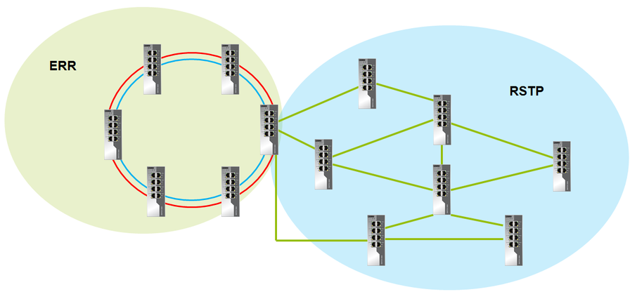
RSTP can be used in conjunction with ERR. But the RSTP ring and the ERR ring should intersect only through one switch.
Summary
ERR is great for organizing sample topologies. For example, a ring or double ring.
Similar topologies are often used for redundancy at industrial sites.
Moreover, with the help of ERR, the second topology can be implemented less reliably, but more budget. This can be done using a duplicate ring.
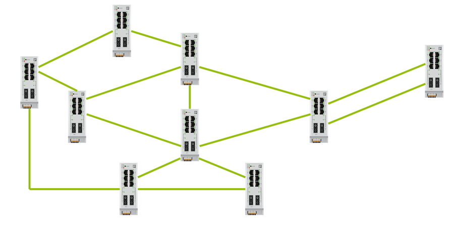
But it is not always possible to apply ERR. There are quite exotic schemes. With one of our customers, we tested the following topology.
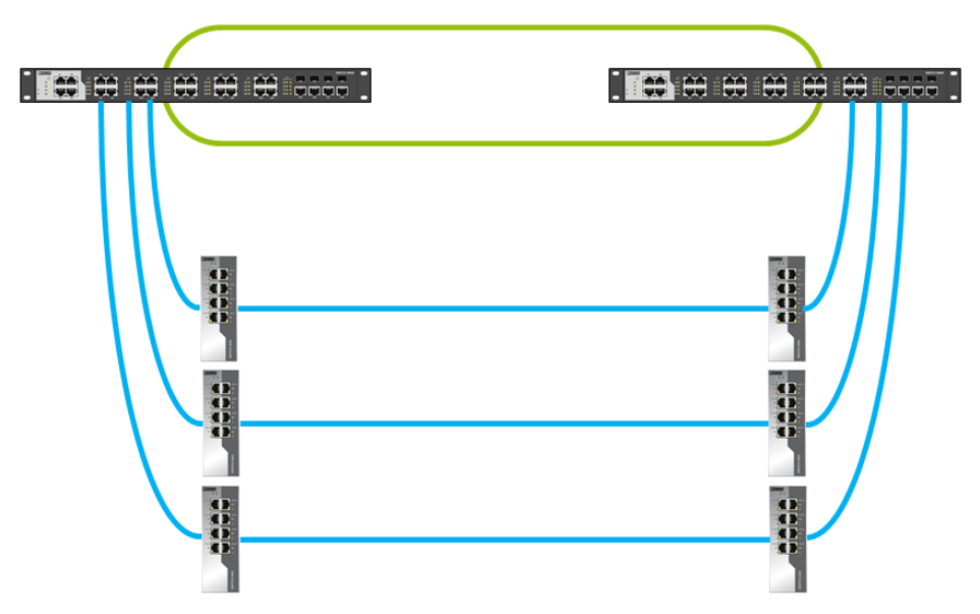
In this case, ERR is not possible to apply. For this scheme we used RSTP. The customer had a strict time requirement for convergence - less than 3 s. To achieve this time it was necessary to clearly define the root switches (main and backup), as well as the cost of ports in manual mode.
As a result, ERR significantly gains in convergence time, but does not provide the flexibility that RSTP provides.
RSTP implementation details
General information
')
Convergence time - 1-10 s
Possible topologies - any
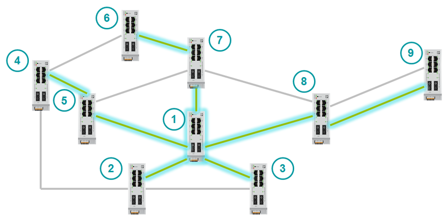
It is widely believed that RSTP allows you to combine switches only in a ring:
But RSTP allows you to connect switches in an arbitrary way. For example, RSTP can handle this topology.
Operating principle
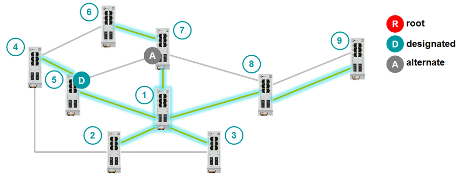
RSTP reduces any topology to a tree. One of the switches becomes the center of the topology - the root switch. The root switch passes the largest amount of data through itself.
The principle of operation of RSTP is as follows:
- power is supplied to the switches;
- root switch is selected;
- other switches determine the fastest path to the root switch;
- the remaining channels are blocked and become backup.
Choosing a root switch
Switches with RSTP exchange BPDU packets. BPDU is a service packet that contains RSTP information. BPDUs are of two types:
- Configuration BPDU.
- Topology Change Notification.
Configuration BPDU is used to build the topology. It is sent only by the root switch. Configuration BPDU contains:
- Sender ID (Bridge ID);
- Root Bridge ID;
- ID of the port from which this packet is sent (Port ID);
- the cost of the route to the root switch (Root Path Cost).
Topology Change Notification can send any switch. They are sent in case of a change in topology.
After switching on, all switches consider themselves root. They begin to send BPDU packets. As soon as the switch receives a BPDU with a smaller Bridge ID than its own, it will no longer consider itself root.
Bridge ID consists of two values - the MAC address and Bridge Priority. We cannot change the MAC address. Bridge Priority defaults to 32768. If you do not change Bridge Priority, the switch with the lowest MAC address becomes the root switch. The switch with the lowest MAC address is the oldest and possibly not the most efficient. It is recommended that you manually identify the root switch topology. To do this, you need to configure a small Bridge Priority on the root switch (for example, 0). You can also define a backup root switch by giving it a slightly larger Bridge Priority (for example, 4096).
Choosing the path to the root switch
The root switch sends BPDU packets to all active ports. BPDU has a Path Cost field. Path Cost denotes the cost of the path. The higher the cost of the path, the longer the packet is transmitted through it. When BPDU passes through a port, a cost is added to the Path Cost field. The added number is called Port Cost.
Adds a specific value to Path Cost when a BPDU passes through a port. That value that adds is called Port Cost (Port Cost) and can be determined both manually and automatically. Port Cost can be determined either manually or automatically.
When a non-root switch has several alternative paths to the root, it chooses the fastest one. He compares the path cost of these paths. The port from which the BPDU came with the lowest Path Cost becomes the root (Root Port).
The cost of ports that are assigned automatically can be viewed in the table:
| Port data rate | Port cost |
|---|---|
| 10 Mb / s | 2 000 000 |
| 100 Mb / s | 200,000 |
| 1 Gb / s | 20,000 |
| 10 Gb / s | 2,000 |
Roles and statuses of ports
Switch ports have several statuses and port roles.
Port statuses (for STP):
- Disabled - inactive.
- Blocking - listens to BPDU, but does not transmit. Data does not transfer.
- Listening - listens and transmits BPDUs. Data does not transfer.
- Learning - listens and transmits BPDUs. Prepares for data transfer - fills the table of MAC-addresses.
- Forwarding - transmits data, listens and transmits BPDUs.
STP convergence time - 30-50 seconds. After switching on the switch, all ports go through all statuses. Each status port is a few seconds. Because of this principle, STP has such a long convergence time. RSTP has fewer port statuses.
Port statuses (for RSTP):
- Discarding - inactive.
- Discarding - listens to BPDU, but does not transmit. Data does not transfer.
- Discarding - listens and transmits BPDU. Data does not transfer.
- Learning - listens and transmits BPDUs. Prepares for data transfer - fills the table of MAC-addresses.
- Forwarding - transmits data, listens and transmits BPDUs.
- In RSTP, the statuses Disabled, Blocking and Listening are combined into one - Discarding.
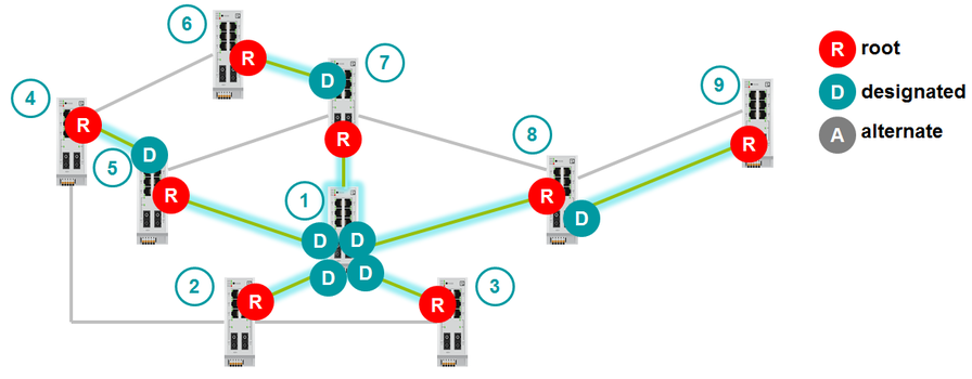
Port Roles:
- Root port - the port through which data is transmitted. It serves as the fastest path to the root switch.
- Designated port - the port through which data is transmitted. Defined for each LAN segment.
- Alternate port - the port through which data is not transmitted. It is an alternative path to the root switch.
- Backup port - the port through which data is not transmitted. It is a backup path for a segment where one port with RSTP support is already connected. Backup port is used if two switch channels are connected to the same segment (read the hub).
- Disabled port - RSTP is disabled on this port.
The selection of Root Port is described above. How is Designated port selected?
First, let's define what a LAN segment is. The LAN segment is a collision domain. For a switch or router, each port forms a separate collision domain. A LAN segment is a channel between switches or routers. If we talk about the hub, then at the hub all the ports are in the same collision domain.
Only one Designated Port is assigned to one segment.
In the case of segments where there are already Root Portes, everything is clear. The second port of the segment becomes the Designated Port.
But there are backup channels where there will be one Designated Port and one Alternate Port. How will they get out? Designated Port will become the port with the lowest Path Cost to the root switch. If Path Cost is equal, then Designated Port will be the port that is located on the switch with the lowest Bridge ID. If the Bridge ID is equal, then the Designated Port becomes the port with the lowest number. The second port will be alternate.
The last moment remains: when is the port assigned to the Backup role? As already stated above, the Backup port is used only when two channels of the switch are connected to the same segment, that is, to the hub. In this case, the Designated Port is selected exactly according to the same criteria:
- Smallest Path Cost to Root Switch.
- Smallest Bridge ID.
- Smallest Port ID.
Maximum number of devices on the network
The IEEE 802.1D standard does not impose strict requirements on the number of devices on a LAN with RSTP. But the standard recommends using no more than 7 switches in one branch (no more than 7 hops), i.e. no more than 15 in the ring. When this value is exceeded, the time of network convergence begins to increase.
ERR implementation details.
General information
Convergence time
ERR convergence time is 15 ms. With the maximum number of switches in the ring and the presence of pairing rings - 18 ms.
Possible topologies
ERR does not allow to freely merge devices as RSTP. ERR has clear topologies that can be used:
- Ring
- Duplicate ring
- Pair up to three rings
Ring
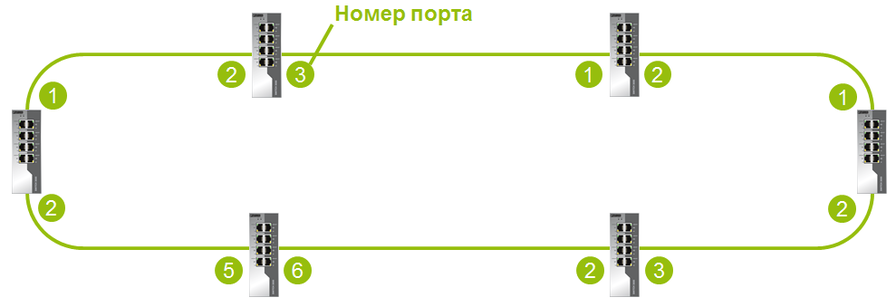
When all switches are combined into one ring in ERR, then on each switch you need to configure the ports that will be involved in building the ring.
Double ring
Switches can be combined into a double ring, which greatly increases the reliability of the ring.
Double Ring Restrictions:
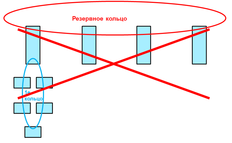
- Double ring cannot be used to pair switches with other rings. For this you need to use Ring Coupling.
- Double ring cannot be used for mating ring.
Pairing rings
When pairing in the network can be no more than 200 devices.
Pairing rings means combining the remaining rings into another ring.
If a ring connects to a pairing ring through a single switch, this is called pairing rings through a single switch . If two switches from a local ring are connected to a pairing ring, this will be a pairing through two switches .
When pairing through one switch on the device, both ports are enabled. The convergence time in this case will be approximately 15-17 ms. With such a pairing, the pairing switch will be a point of failure, since having lost this switch, the whole ring is lost at once. Pairing through two switches avoids this.
It is possible to match duplicated rings.
Path control
The Path Control function allows you to configure the ports through which data will be transmitted in the normal mode of operation. If the channel fails and the network is rebuilt to the backup topology, then after the restoration of the channel, the network will be rebuilt back to the specified topology.
This feature saves redundant cable. Moreover, the topology used for troubleshooting will always be known.
The basic topology switches to the backup in 15 ms. Re-switching when restoring the network will take about 30 ms.
Limitations:
- Cannot be used with dual ring.
- The feature must be enabled on all switches in the network.
- One of the switches is configured as a Path Control wizard.
- Automatic transition to the main topology after recovery is carried out after 1 second by default (this parameter can be changed using SNMP in the range from 0 s to 99 s).
Operating principle
ERR principle of operation
For example, consider the six switches - 1-6. Switches are united in a ring. Each switch uses two ports to connect to the ring and stores their status. Switches send port status to each other. These device data are used to set the initial state of the ports.
Ports have only two roles - Blocked and Forwarding .
The switch with the highest MAC address blocks the port. All other ports in the ring transmit data.
If the Blocked port stops working, then the next port with the highest MAC address becomes Blocked.
After booting, switches begin to send Ring Protocol Data Unit (R-PDU). R-PDU is transmitted using multicast. The R-PDU is a service message, as is the BPDU in RSTP. The R-PDU contains the switch port statuses and its MAC address.
Algorithm of actions in case of channel failure
When the link fails, the switches send an R-PDU to notify you of the port status change.
Algorithm of actions during the restoration of the channel
When the failed link is brought into service, the switches send an R-PDU to notify you of the port status change.
The switch with the highest MAC address becomes the new root switch.
The failed channel becomes backup.
After recovery, one of the channel ports remains blocked, and the second is transferred to the forwarding state. A blocked port becomes the port with the highest speed. If the speeds are equal, then the switch port with the highest MAC address will be blocked. This principle allows you to block a port that goes from the blocked state to the forwarding state at maximum speed.
Maximum number of devices on the network
The maximum number of switches in the ERR ring is 200.
ERR and RSTP interaction
RSTP can be used in conjunction with ERR. But the RSTP ring and the ERR ring should intersect only through one switch.
Summary
ERR is great for organizing sample topologies. For example, a ring or double ring.
Similar topologies are often used for redundancy at industrial sites.
Moreover, with the help of ERR, the second topology can be implemented less reliably, but more budget. This can be done using a duplicate ring.
But it is not always possible to apply ERR. There are quite exotic schemes. With one of our customers, we tested the following topology.
In this case, ERR is not possible to apply. For this scheme we used RSTP. The customer had a strict time requirement for convergence - less than 3 s. To achieve this time it was necessary to clearly define the root switches (main and backup), as well as the cost of ports in manual mode.
As a result, ERR significantly gains in convergence time, but does not provide the flexibility that RSTP provides.
Source: https://habr.com/ru/post/460633/
All Articles