Wireless module for capacitive soil moisture sensor on nRF52832
Hello everyone, today I will talk about how I decided to upgrade the soil moisture sensor with Aliexpress. About a month ago, a soil moisture sensor was purchased. Why did I buy and I do not know, probably all because of the price of 40 rubles :)
Having received and successfully tested the sensor (with the help of Arduino Nano), I began to think where to attach it to an already operating system based on Meissensors (which I will explain later). Since the sensor is super cheap, I would very much like to find a cheap and unpretentious solution.
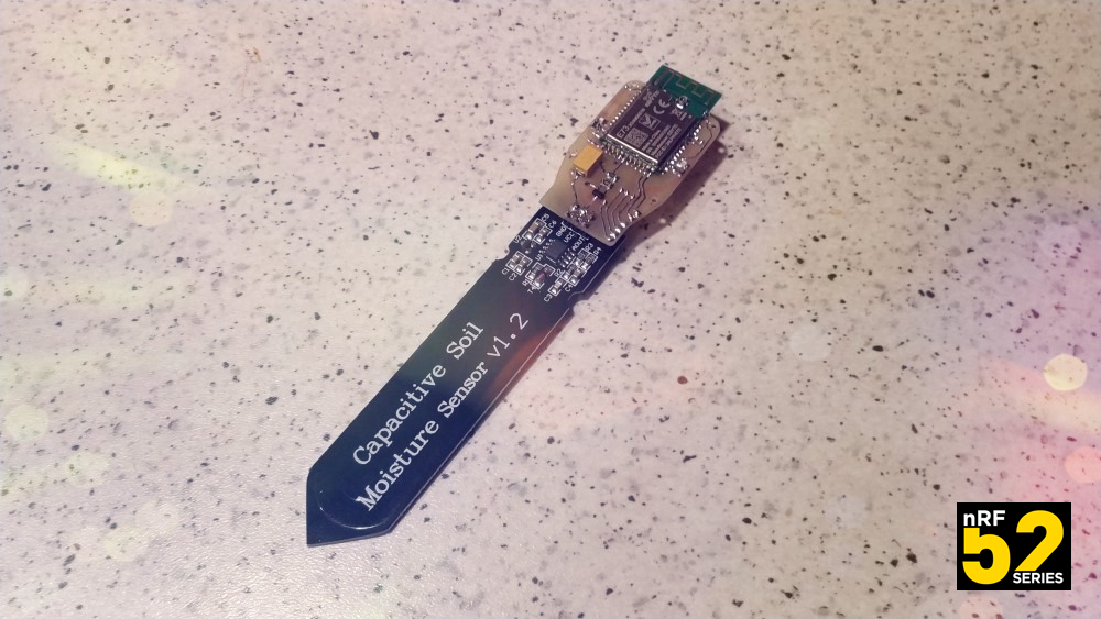
The sensor circuit is built on the TLC555 timer chip. A voltage regulator XC6206P332 ( datasheet ) of 3.3V has been added to the circuit, respectively, the circuit can be powered from a source of maximum 6v. When the supply voltage is below 3.3V, the stabilizer gives the output as well, which it receives at the input.
')
For about two months now, two nRF52832 modules from EBYTE - E73-2G4M04S1B have been idle. Very cheap modules, the price leaves all other nRF52 modules far behind.

But they have 2 essential minuses for me. The first and less important is the size of the module. They are pretty big. The second minus, more important is the absence of two small elements in the circuit, due to which the module loses half of its attractiveness. Missing elements are two inductors connected to the DCC and DEC4 legs. This is bad because it does not allow the use of modules in low-power mode, 7-8mA VS 15-16mA. Why they did not put them, I can not understand, the option "because of savings" does not fit, since the scheme could save on other elements. In general, we add inductance installation and the presence of DC-DC mode.
The next thing you need to solve is the power management of the sensor. Since our theme is a battery theme, constant power is a bad option. The simplest thing that immediately suggests itself is the use of the transistor in the key mode. The choice fell on the field p-channel transistor IRLML6402TRPBF.
The next thing you had to think about was the programming port, for SWD and Serial I just made pads. Of course, I also added a micro connector, which I use in other devices 2x3P | 6pin | 1.27mm | SMT | Pin Header Female , but this is now a purely optional thing.
You also need to add a clock button and at least one LED, so that it would be easier to understand whether it works or not :).
The next thing you had to do was decide how to connect the node of the radio module and the capacitive sensor. The outlet that is installed on the sensor and the wires going in the kit did not want to use. The pitch of holes in the connector on the board where the socket is soldered is 2.54 mm, as well as an additional backup row on the board. It was decided to use the usual “comb” with a step of 2.54, and using both rows at once would add additional rigidity to the joint.
It seems to be everything, from the buns, several elements that can be left or soldered for a rainy day and an outlet with a wire (somewhere useful :)).
The fee, as usual, did in the program Diptreys. The first option was made for LUT, actually about what happened just in this article. Later was made option board for order in production.

After etching, tinning, cutting, drilling and soldering, it is time to test. In general, I did not expect anything special from the sensor on the module from EBYTE, especially with some external moisture meter with Ali. But in the end I was even surprised by some results. The consumption in the data transfer mode was no more than 9 mA (per half discharged battery), the consumption in the measurement mode was no more than 5 mA. Sleep consumption was 2.1-2.2µA !!!

Total that the sensor can now. Work in reduced power consumption mode. Measure and transmit to the controller of the DD via the Maysensor network readings of soil moisture, temperature readings, readings of the remaining battery charge, readings of the level of the radio signal.

And what is Maysensors?
A is a community of open source software developers. This protocol is developed by the community to create radio and wired networks. Initially, the project was developed for the Arduino platform.
Supported hardware platforms: Linux / Raspberry Pi / Orange Pi | ATMega 328P | ESP8266 | ESP32 | nRF5x | Atmel SAMD used in Arduino Zero (Cortex M0) | Teensy3 (MK66FX1M0VMD18) | STM32F1.
Supported Radio Transmitters: NRF24L01 | RFM69 | RFM95 (LoRa) | nRF5x
Supported wired connection type: RS485
Supported communication types between gate and controller: MQTT | Serial USB | WiFi | Ethernet | GSM
The software is naturally test, which I would certainly add (and add) is taking into account the discharge coefficient of the battery, although I use the reference voltage setting in the software as external battery vdd / 4, but still there is a slight noise when measuring with different voltage levels. It is also not yet clear whether or not to enter the temperature coefficient into the calculations. Unclear because there is no statistics. But, in general, the output is very nice results :). The cost of all that had to be added to the Chinese humidity sensor was about 400 rubles. Not bad at all.
GitHub project
So here came a project, ... while the Arduino ala module, but provided places for attachment to the case in advance, so that will continue to be the case. It consumes little, basically always sleeps with a consumption of about 2 µA, so the CR2450 battery should last long.
A place where you will always be happy to help everyone who wants to get acquainted with MYSENSORS (installing boards, working with nRF5 microcontrollers in the Arduino IDE environment, tips on working with mysensors protocol, discussing projects - telegrams chat @mysensors_rus .
Having received and successfully tested the sensor (with the help of Arduino Nano), I began to think where to attach it to an already operating system based on Meissensors (which I will explain later). Since the sensor is super cheap, I would very much like to find a cheap and unpretentious solution.
The sensor circuit is built on the TLC555 timer chip. A voltage regulator XC6206P332 ( datasheet ) of 3.3V has been added to the circuit, respectively, the circuit can be powered from a source of maximum 6v. When the supply voltage is below 3.3V, the stabilizer gives the output as well, which it receives at the input.
')
For about two months now, two nRF52832 modules from EBYTE - E73-2G4M04S1B have been idle. Very cheap modules, the price leaves all other nRF52 modules far behind.
But they have 2 essential minuses for me. The first and less important is the size of the module. They are pretty big. The second minus, more important is the absence of two small elements in the circuit, due to which the module loses half of its attractiveness. Missing elements are two inductors connected to the DCC and DEC4 legs. This is bad because it does not allow the use of modules in low-power mode, 7-8mA VS 15-16mA. Why they did not put them, I can not understand, the option "because of savings" does not fit, since the scheme could save on other elements. In general, we add inductance installation and the presence of DC-DC mode.
The next thing you need to solve is the power management of the sensor. Since our theme is a battery theme, constant power is a bad option. The simplest thing that immediately suggests itself is the use of the transistor in the key mode. The choice fell on the field p-channel transistor IRLML6402TRPBF.
The next thing you had to think about was the programming port, for SWD and Serial I just made pads. Of course, I also added a micro connector, which I use in other devices 2x3P | 6pin | 1.27mm | SMT | Pin Header Female , but this is now a purely optional thing.
You also need to add a clock button and at least one LED, so that it would be easier to understand whether it works or not :).
The next thing you had to do was decide how to connect the node of the radio module and the capacitive sensor. The outlet that is installed on the sensor and the wires going in the kit did not want to use. The pitch of holes in the connector on the board where the socket is soldered is 2.54 mm, as well as an additional backup row on the board. It was decided to use the usual “comb” with a step of 2.54, and using both rows at once would add additional rigidity to the joint.
It seems to be everything, from the buns, several elements that can be left or soldered for a rainy day and an outlet with a wire (somewhere useful :)).
The fee, as usual, did in the program Diptreys. The first option was made for LUT, actually about what happened just in this article. Later was made option board for order in production.
After etching, tinning, cutting, drilling and soldering, it is time to test. In general, I did not expect anything special from the sensor on the module from EBYTE, especially with some external moisture meter with Ali. But in the end I was even surprised by some results. The consumption in the data transfer mode was no more than 9 mA (per half discharged battery), the consumption in the measurement mode was no more than 5 mA. Sleep consumption was 2.1-2.2µA !!!
Total that the sensor can now. Work in reduced power consumption mode. Measure and transmit to the controller of the DD via the Maysensor network readings of soil moisture, temperature readings, readings of the remaining battery charge, readings of the level of the radio signal.
And what is Maysensors?
A is a community of open source software developers. This protocol is developed by the community to create radio and wired networks. Initially, the project was developed for the Arduino platform.
Supported hardware platforms: Linux / Raspberry Pi / Orange Pi | ATMega 328P | ESP8266 | ESP32 | nRF5x | Atmel SAMD used in Arduino Zero (Cortex M0) | Teensy3 (MK66FX1M0VMD18) | STM32F1.
Supported Radio Transmitters: NRF24L01 | RFM69 | RFM95 (LoRa) | nRF5x
Supported wired connection type: RS485
Supported communication types between gate and controller: MQTT | Serial USB | WiFi | Ethernet | GSM
Program code
uint16_t m_s_m; uint16_t m_s_m2; uint16_t m_s_m_calc; boolean flagSendmsm = 0; float celsius = 0.0; uint32_t rawTemperature = 0; uint32_t rawTemperature2 = 0; uint16_t currentBatteryPercent; uint16_t batteryVoltage = 0; uint16_t battery_vcc_min = 2300; uint16_t battery_vcc_max = 3000; int16_t linkQuality; //#define MY_DEBUG #define MY_DISABLED_SERIAL #define MY_RADIO_NRF5_ESB #define MY_RF24_PA_LEVEL (NRF5_PA_MAX) //#define MY_PASSIVE_NODE #define MY_NODE_ID 83 #define MY_PARENT_NODE_ID 0 #define MY_PARENT_NODE_IS_STATIC #define MY_TRANSPORT_UPLINK_CHECK_DISABLED #define MSM_SENS_ID 1 #define MSM_SENS_C_ID 2 #define TEMP_INT_ID 3 #define SIGNAL_Q_ID 10 #include <MySensors.h> MyMessage msg_msm(MSM_SENS_ID, V_LEVEL); MyMessage msg_msm2(MSM_SENS_C_ID, V_LEVEL); MyMessage msg_temp(TEMP_INT_ID, V_TEMP); void preHwInit() { pinMode(6, OUTPUT); digitalWrite(6, HIGH); pinMode(15, OUTPUT); pinMode(5, INPUT); } void before() { delay(3000); NRF_POWER->DCDCEN = 1; NRF_UART0->ENABLE = 0; analogReadResolution(12); analogReference(AR_VDD4); NRF_CLOCK->TASKS_HFCLKSTART = 1; NRF_TEMP->TASKS_STOP; NRF_TEMP->EVENTS_DATARDY = 0; NRF_TEMP->INTENSET = 1; } void presentation() { sendSketchInfo("PWS GREEN nRF52", "1.01"); wait(300); present(MSM_SENS_ID, S_CUSTOM, "DATA - SOIL MOISTURE"); wait(300); present(MSM_SENS_C_ID, S_CUSTOM, "% - SOIL MOISTURE"); wait(300); present(TEMP_INT_ID, S_TEMP, "TEMPERATURE"); wait(300); present(SIGNAL_Q_ID, S_CUSTOM, "SIGNAL QUALITY"); wait(300); } void setup() { } void loop() { int_temp(); digitalWrite(15, HIGH); sleep(100); digitalWrite(15, LOW); msm (); digitalWrite(15, HIGH); sleep(100); digitalWrite(15, LOW); wait(50); if (flagSendmsm == 1) { send(msg_msm2.set(m_s_m_calc), 1); wait(3000, 1, 37); wait(200); send(msg_msm.set(m_s_m), 1); wait(3000, 1, 37); flagSendmsm = 0; } wait(200); send(msg_temp.set(celsius, 1), 1); wait(3000, 1, 0); sleep(15000); //sleep(2000); sendBatteryStatus(); sleep(21600000); //6h //sleep(43200000); //12h //sleep(86400000); //24h //sleep(20000); //20s } void int_temp() { for (byte i = 0; i < 10; i++) { NRF_TEMP->TASKS_START = 1; while (!(NRF_TEMP->EVENTS_DATARDY)) {} rawTemperature = NRF_TEMP->TEMP; rawTemperature2 = rawTemperature2 + rawTemperature; wait(10); } celsius = ((((float)rawTemperature2) / 10) / 4.0); rawTemperature2 = 0; } void msm () { digitalWrite(6, LOW); wait(500); for (byte i = 0; i < 10; i++) { m_s_m = analogRead(5); m_s_m2 = m_s_m2 + m_s_m; wait(50); } m_s_m = m_s_m2 / 10; m_s_m2 = 0; digitalWrite(6, HIGH); wait(50); if(m_s_m >3000){ m_s_m = 3000; } if(m_s_m <1100){ m_s_m = 1100; } m_s_m_calc = map(m_s_m, 3000, 1100, 0, 100); flagSendmsm = 1; } void sendBatteryStatus() { wait(100); batteryVoltage = hwCPUVoltage(); wait(20); if (batteryVoltage > battery_vcc_max) { currentBatteryPercent = 100; } else if (batteryVoltage < battery_vcc_min) { currentBatteryPercent = 0; } else { currentBatteryPercent = (100 * (batteryVoltage - battery_vcc_min)) / (battery_vcc_max - battery_vcc_min); } sendBatteryLevel(currentBatteryPercent, 1); wait(3000, C_INTERNAL, I_BATTERY_LEVEL); linkQuality = calculationRxQuality(); wait(50); sendSignalStrength(linkQuality, 1); wait(2000, 1, V_VAR1); } //****************************** very experimental ******************************* bool sendSignalStrength(const int16_t level, const bool ack) { return _sendRoute(build(_msgTmp, GATEWAY_ADDRESS, SIGNAL_Q_ID, C_SET, V_VAR1, ack).set(level)); } int16_t calculationRxQuality() { int16_t nRFRSSI_temp = transportGetReceivingRSSI(); int16_t nRFRSSI = map(nRFRSSI_temp, -85, -40, 0, 100); if (nRFRSSI < 0) { nRFRSSI = 0; } if (nRFRSSI > 100) { nRFRSSI = 100; } return nRFRSSI; } //****************************** very experimental ******************************* The software is naturally test, which I would certainly add (and add) is taking into account the discharge coefficient of the battery, although I use the reference voltage setting in the software as external battery vdd / 4, but still there is a slight noise when measuring with different voltage levels. It is also not yet clear whether or not to enter the temperature coefficient into the calculations. Unclear because there is no statistics. But, in general, the output is very nice results :). The cost of all that had to be added to the Chinese humidity sensor was about 400 rubles. Not bad at all.
Video with tests
Photo


GitHub project
So here came a project, ... while the Arduino ala module, but provided places for attachment to the case in advance, so that will continue to be the case. It consumes little, basically always sleeps with a consumption of about 2 µA, so the CR2450 battery should last long.
A place where you will always be happy to help everyone who wants to get acquainted with MYSENSORS (installing boards, working with nRF5 microcontrollers in the Arduino IDE environment, tips on working with mysensors protocol, discussing projects - telegrams chat @mysensors_rus .
Source: https://habr.com/ru/post/460587/
All Articles