Wireless water leak sensor on nRF52832, DIY project
Greetings to all readers of the section "DIY or DIY" on Habr! Today I want to talk about my next project, this article will be about the battery leakage sensor on battery power. As in previous projects, this device works on the nRF52832 microcontroller. There are three versions of this sensor, all three versions use ready-made modules with nRF52832, in this article we will focus on the middle version in which the YJ-17103 module from HOLYIOT is used.

The liquid detector is implemented on the SN74LVC1G00 | microcircuit | Datashit . I will briefly describe the circuit design and the principle of operation. Electrode No. 1 of the sensor is connected to ground, electrode No. 2 of the sensor is connected to legs A and B of the SN74LVC1G00 chip through a 100Ohm resistor, as well as 3.3V through a 1M resistor to this line, as well as the capacitance added to the circuit. When there is no contact with liquid on the legs of the A and B chips, there is a logical unit, respectively, on the Y leg connected to the MK leg (programmatically configured to detect an interrupt through the built-in comporator) logical zero. As soon as there is a contact with the liquid and the legs A and B are at a low level, the signal at the leg Y of the SN74LVC1G00 chip is also inverted, which causes an interrupt, which in turn will bring the MK out of sleep. In the future, the SN74LVC1G00 chip will probably be replaced by the SN74LVC1G14 chip | Datasheet , and maybe will not :). Detection of fluid from the legs of MK through the built-in comporator is not planned.
Like all my other projects, this is also an Arduino project and, like all projects over the past year (approximately), this is also done for the Mysensors project. As in my other articles, I will touch on the subject of Mysensors in this article.
')
Mysensors is an open source software development community. This protocol is developed by the community to create radio and wired networks. Initially, the project was developed for the Arduino platform. The standard Mysensors network consists of a gate (gateway), repeaters and end devices (nodes). Up to 254 devices can be in one network, each device can be equipped with up to 254 sensors, sensors, and actuating nodes. Network operation, data processing, script execution and interaction with other devices is performed using the UD controller. Some of the controllers (Majordomo) support work with several networks and Mysensors (multi-geographic), respectively, the networks can be much more than one managed by one controller.
Supported hardware platforms : Linux / Raspberry Pi / Orange Pi | ATMega 328P | ESP8266 | ESP32 | nRF5x (Cortex M0, M4) | Atmel SAMD used in Arduino Zero (Cortex M0) | Teensy3 (MK66FX1M0VMD18) | STM32F1.
Supported Radio Transmitters : NRF24L01 | RFM69 | RFM95 (LoRa) | nRF5x
Supported wired connection type : RS485
Supported communication types between gate and controller : MQTT | Serial USB | WiFi | Ethernet | GSM
Let's go back to the leak sensor. The device is powered by CR2430, CR2450 or CR2477 batteries. Sleep consumption is less than 3µA. The transfer speed is 250Kbps, 10-15ms. The power consumption at the time of transmission is no more than 8mA. Theoretically, the term of work on one battery is approximately equal to the period of self-discharge of the battery. In practice, everything is certainly less rosy, since there is a registration procedure, presentations, periodic sending of the charge level, so that the battery life from one battery is rather closer to the value - self-discharge period / 2 :). Power is supplied directly from the battery, the battery charge level control is performed directly from the pin VDD. The sensor has an RGB LED for indicating the registration of the sensor in the network, for indicating service modes and for indicating leak detection. Naturally, the LED may not be used at all or be used in part.
The device board was made for its further manufacture according to the LUT method. Therefore, from the nuances of this option, this is an increased width of the lines, increased distances between the lines, increased areas for interlayer transitions (for more convenient drilling of holes), and the lack of filling in empty areas due to the small area of the board. Later, an option was made for the order in production.

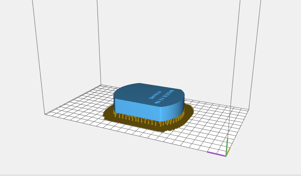
The device case was designed in two parts. The top cover with places for fixing the board and the lower part (bath) with 2 holes for steel contact screws (sealing possible with silicone sealant under the head of screws or not required) and two tubes for buttons (reset and modes) on the board. Printing was performed on an ANICUBIC PHOTON SLA 3D printer. After printing, an emery paper 320 and 1000 were machined to fit the joints of the cover and the bottom of the case.

nRF52832 software is configured to work in low power mode (DC-DC Mode). The output of the MK from sleep on a signal from the chip SN74LVC1G00 is configured through the internal comparator LPCOMP. The device also has a clock button for implementing service modes, such as device binding, device zeroing, etc. The button is wound up on the same leg of the MK as the leak detector. Both lines are separated by Schottky diodes. The SN74LVC1G00 chip in monitoring mode does not consume anything. Power management of the chip is carried out with legs MK.
At the moment, the development of a water leakage controller is almost complete, with which these sensors should work.
Github project
(gerber files, soft, shell models, components list)
A place where you are always happy to help everyone who wants to get acquainted with MYSENSORS (installing boards, working with nRF5 microcontrollers in the Arduino IDE environment, tips on working with the mysensors protocol, discussing new authoring projects - chat @mysensors_rus .
The liquid detector is implemented on the SN74LVC1G00 | microcircuit | Datashit . I will briefly describe the circuit design and the principle of operation. Electrode No. 1 of the sensor is connected to ground, electrode No. 2 of the sensor is connected to legs A and B of the SN74LVC1G00 chip through a 100Ohm resistor, as well as 3.3V through a 1M resistor to this line, as well as the capacitance added to the circuit. When there is no contact with liquid on the legs of the A and B chips, there is a logical unit, respectively, on the Y leg connected to the MK leg (programmatically configured to detect an interrupt through the built-in comporator) logical zero. As soon as there is a contact with the liquid and the legs A and B are at a low level, the signal at the leg Y of the SN74LVC1G00 chip is also inverted, which causes an interrupt, which in turn will bring the MK out of sleep. In the future, the SN74LVC1G00 chip will probably be replaced by the SN74LVC1G14 chip | Datasheet , and maybe will not :). Detection of fluid from the legs of MK through the built-in comporator is not planned.
Like all my other projects, this is also an Arduino project and, like all projects over the past year (approximately), this is also done for the Mysensors project. As in my other articles, I will touch on the subject of Mysensors in this article.
')
Mysensors is an open source software development community. This protocol is developed by the community to create radio and wired networks. Initially, the project was developed for the Arduino platform. The standard Mysensors network consists of a gate (gateway), repeaters and end devices (nodes). Up to 254 devices can be in one network, each device can be equipped with up to 254 sensors, sensors, and actuating nodes. Network operation, data processing, script execution and interaction with other devices is performed using the UD controller. Some of the controllers (Majordomo) support work with several networks and Mysensors (multi-geographic), respectively, the networks can be much more than one managed by one controller.
Supported hardware platforms : Linux / Raspberry Pi / Orange Pi | ATMega 328P | ESP8266 | ESP32 | nRF5x (Cortex M0, M4) | Atmel SAMD used in Arduino Zero (Cortex M0) | Teensy3 (MK66FX1M0VMD18) | STM32F1.
Supported Radio Transmitters : NRF24L01 | RFM69 | RFM95 (LoRa) | nRF5x
Supported wired connection type : RS485
Supported communication types between gate and controller : MQTT | Serial USB | WiFi | Ethernet | GSM
Let's go back to the leak sensor. The device is powered by CR2430, CR2450 or CR2477 batteries. Sleep consumption is less than 3µA. The transfer speed is 250Kbps, 10-15ms. The power consumption at the time of transmission is no more than 8mA. Theoretically, the term of work on one battery is approximately equal to the period of self-discharge of the battery. In practice, everything is certainly less rosy, since there is a registration procedure, presentations, periodic sending of the charge level, so that the battery life from one battery is rather closer to the value - self-discharge period / 2 :). Power is supplied directly from the battery, the battery charge level control is performed directly from the pin VDD. The sensor has an RGB LED for indicating the registration of the sensor in the network, for indicating service modes and for indicating leak detection. Naturally, the LED may not be used at all or be used in part.
The device board was made for its further manufacture according to the LUT method. Therefore, from the nuances of this option, this is an increased width of the lines, increased distances between the lines, increased areas for interlayer transitions (for more convenient drilling of holes), and the lack of filling in empty areas due to the small area of the board. Later, an option was made for the order in production.
The device case was designed in two parts. The top cover with places for fixing the board and the lower part (bath) with 2 holes for steel contact screws (sealing possible with silicone sealant under the head of screws or not required) and two tubes for buttons (reset and modes) on the board. Printing was performed on an ANICUBIC PHOTON SLA 3D printer. After printing, an emery paper 320 and 1000 were machined to fit the joints of the cover and the bottom of the case.
Sensor Photos


Test program code
wl_standart_test.ino
MyBoardNRF5.h
bool button_flag; bool send_flag; bool detection; bool nosleep; byte timer; bool AckG; bool AckB; bool AckL; bool PRESENT_ACK; bool flag_lq; unsigned long SLEEP_TIME = 172800000; //48 hours //unsigned long SLEEP_TIME = 3600000; //1 hour unsigned long oldmillis; unsigned long newmillis; unsigned long interrupt_time; unsigned long SLEEP_TIME_W; uint16_t currentBatteryPercent; uint16_t batteryVoltage = 0; uint16_t battery_vcc_min = 2300; uint16_t battery_vcc_max = 3000; int16_t linkQuality; #define MY_DISABLED_SERIAL #define MY_RADIO_NRF5_ESB #define MY_RF24_PA_LEVEL (NRF5_PA_MAX) //#define MY_PASSIVE_NODE #define MY_NODE_ID 86 #define MY_PARENT_NODE_ID 0 #define MY_PARENT_NODE_IS_STATIC #define MY_TRANSPORT_UPLINK_CHECK_DISABLED #define INTR_PIN 3 //(PORT0, gpio 5) #include <MySensors.h> // see https://www.mysensors.org/download/serial_api_20 #define W_L_SENS_CHILD_ID 0 #define LINK_QUALITY_CHILD_ID 253 MyMessage sensMsg(W_L_SENS_CHILD_ID, V_VAR1); //MyMessage voltMsg(CHILD_ID_VOLT, V_VOLTAGE); void preHwInit() { pinMode(POWER_PIN, OUTPUT); digitalWrite(POWER_PIN, HIGH); wait(3000); pinMode(RED_LED, OUTPUT); digitalWrite(RED_LED, HIGH); pinMode(GREEN_LED, OUTPUT); digitalWrite(GREEN_LED, HIGH); pinMode(BLUE_LED, OUTPUT); digitalWrite(BLUE_LED, HIGH); pinMode(PIN_BUTTON, INPUT); pinMode(W_L_SENS, INPUT); //pinMode(24, OUTPUT); //pinMode(20, OUTPUT); } void before() { NRF_POWER->DCDCEN = 1; NRF_UART0->ENABLE = 0; digitalWrite(BLUE_LED, LOW); sleep(50); digitalWrite(BLUE_LED, HIGH); } void presentation() { sendSketchInfo("EFEKTA ST WL Sensor", "1.1"); present(W_L_SENS_CHILD_ID, S_CUSTOM, "SWITCH STATUS"); present(LINK_QUALITY_CHILD_ID, S_CUSTOM, "LINK_QUALITY"); } void setup() { digitalWrite(BLUE_LED, LOW); wait(100); digitalWrite(BLUE_LED, HIGH); wait(200); digitalWrite(BLUE_LED, LOW); wait(100); digitalWrite(BLUE_LED, HIGH); lpComp(); detection = false; SLEEP_TIME_W = SLEEP_TIME; wait(100); sendBatteryStatus(); wait(100); send(sensMsg.set(detection), 1); wait(2000, 1, V_VAR1); } void loop() { if (nosleep == 0) { oldmillis = millis(); sleep(SLEEP_TIME_W); } if (detection) { if (digitalRead(PIN_BUTTON) == 1 && button_flag == 0 && digitalRead(W_L_SENS) == 0) { //back side button detection button_flag = 1; nosleep = 1; } if (digitalRead(PIN_BUTTON) == 1 && button_flag == 1 && digitalRead(W_L_SENS) == 0) { digitalWrite(GREEN_LED, LOW); wait(10); digitalWrite(GREEN_LED, HIGH); wait(50); } if (digitalRead(PIN_BUTTON) == 0 && button_flag == 1 && digitalRead(W_L_SENS) == 0) { nosleep = 0; button_flag = 0; digitalWrite(GREEN_LED, HIGH); lpComp_reset(); } if (digitalRead(W_L_SENS) == 1 && digitalRead(PIN_BUTTON) == 0) { //sens detection newmillis = millis(); interrupt_time = newmillis - oldmillis; SLEEP_TIME_W = SLEEP_TIME_W - interrupt_time; send(sensMsg.set(detection), 1); wait(3000, 1, V_VAR1); if (AckG == 1) { while (timer < 10) { timer++; digitalWrite(BLUE_LED, LOW); wait(20); digitalWrite(BLUE_LED, HIGH); wait(30); } timer = 0; AckG = 0; wait(200); } else { while (timer < 10) { timer++; digitalWrite(RED_LED, LOW); wait(20); digitalWrite(RED_LED, HIGH); wait(30); } timer = 0; send(sensMsg.set(detection), 1); wait(3000, 1, V_VAR1); if (AckG == 1) { while (timer < 10) { timer++; digitalWrite(BLUE_LED, LOW); wait(20); digitalWrite(BLUE_LED, HIGH); wait(30); } timer = 0; AckG = 0; } else { while (timer < 10) { timer++; digitalWrite(RED_LED, LOW); wait(20); digitalWrite(RED_LED, HIGH); wait(30); } timer = 0; } lpComp_reset(); } } if (SLEEP_TIME_W < 60000) { SLEEP_TIME_W = SLEEP_TIME; sendBatteryStatus(); } } else { //if (detection == -1) { SLEEP_TIME_W = SLEEP_TIME; sendBatteryStatus(); } } void receive(const MyMessage & message) { if (message.type == V_VAR1) { if (message.sensor == W_L_SENS_CHILD_ID) { if (mGetCommand(message) == 1) { if (message.isAck()) { AckG = 1; } else { } } } } if (message.type == I_BATTERY_LEVEL) { if (message.sensor == 255) { if (mGetCommand(message) == 3) { if (message.isAck()) { AckB = 1; } else { } } } } if (message.type == V_VAR1) { if (message.sensor == 255) { if (mGetCommand(message) == 1) { if (message.isAck()) { AckL = 1; } else { } } } } } void sendBatteryStatus() { wait(100); batteryVoltage = hwCPUVoltage(); wait(20); if (batteryVoltage > battery_vcc_max) { currentBatteryPercent = 100; } else if (batteryVoltage < battery_vcc_min) { currentBatteryPercent = 0; } else { currentBatteryPercent = (100 * (batteryVoltage - battery_vcc_min)) / (battery_vcc_max - battery_vcc_min); } sendBatteryLevel(currentBatteryPercent, 1); wait(3000, C_INTERNAL, I_BATTERY_LEVEL); if (AckB == 1) { AckB = 0; flag_lq = 1; } else { sendBatteryLevel(currentBatteryPercent, 1); wait(3000, C_INTERNAL, I_BATTERY_LEVEL); if (AckB == 1) { AckB = 0; flag_lq = 1; } } //send(powerMsg.set(batteryVoltage), 1); //wait(2000, 1, V_VAR1); //sleep(10000); // if (flag_lq == 1) { linkQuality = calculationRxQuality(); wait(50); sendSignalStrength(linkQuality, 1); wait(2000, 1, V_VAR1); if (AckL == 1) { AckL = 0; } else { sendSignalStrength(linkQuality, 1); wait(2000, 1, V_VAR1); if (AckL == 1) { AckG = 0; } } flag_lq = 0; } } void lpComp() { NRF_LPCOMP->PSEL = INTR_PIN; NRF_LPCOMP->ANADETECT = 1; NRF_LPCOMP->INTENSET = B0100; NRF_LPCOMP->ENABLE = 1; NRF_LPCOMP->TASKS_START = 1; NVIC_SetPriority(LPCOMP_IRQn, 15); NVIC_ClearPendingIRQ(LPCOMP_IRQn); NVIC_EnableIRQ(LPCOMP_IRQn); } void s_lpComp() { if ((NRF_LPCOMP->ENABLE) && (NRF_LPCOMP->EVENTS_READY)) { NRF_LPCOMP->INTENCLR = B0100; } } void r_lpComp() { NRF_LPCOMP->INTENSET = B0100; } #if __CORTEX_M == 0x04 #define NRF5_RESET_EVENT(event) \ event = 0; \ (void)event #else #define NRF5_RESET_EVENT(event) event = 0 #endif void lpComp_reset () { s_lpComp(); detection = false; NRF_LPCOMP->EVENTS_UP = 0; r_lpComp(); } //****************************** very experimental ******************************* bool sendSignalStrength(const int16_t level, const bool ack) { return _sendRoute(build(_msgTmp, GATEWAY_ADDRESS, NODE_SENSOR_ID, C_SET, V_VAR1, ack).set(level)); } int16_t calculationRxQuality() { int16_t nRFRSSI_temp = transportGetReceivingRSSI(); int16_t nRFRSSI = map(nRFRSSI_temp, -85, -40, 0, 100); if (nRFRSSI < 0) { nRFRSSI = 0; } if (nRFRSSI > 100) { nRFRSSI = 100; } return nRFRSSI; } //****************************** very experimental ******************************* extern "C" { void LPCOMP_IRQHandler(void) { detection = true; NRF5_RESET_EVENT(NRF_LPCOMP->EVENTS_UP); NRF_LPCOMP->EVENTS_UP = 0; MY_HW_RTC->CC[0] = (MY_HW_RTC->COUNTER + 2); } } MyBoardNRF5.h
#ifndef _MYBOARDNRF5_H_ #define _MYBOARDNRF5_H_ #ifdef __cplusplus extern "C" { #endif // __cplusplus #define PINS_COUNT (32u) #define NUM_DIGITAL_PINS (32u) #define NUM_ANALOG_INPUTS (8u) #define NUM_ANALOG_OUTPUTS (8u) #define PIN_LED1 (27) #define PIN_LED2 (25) #define PIN_LED3 (26) #define RED_LED (PIN_LED1) #define GREEN_LED (PIN_LED2) #define BLUE_LED (PIN_LED3) #define PIN_BUTTON (14) #define W_L_SENS (8) #define POWER_PIN (7) #define PIN_SERIAL_RX (12) #define PIN_SERIAL_TX (11) #ifdef __cplusplus } #endif #endif nRF52832 software is configured to work in low power mode (DC-DC Mode). The output of the MK from sleep on a signal from the chip SN74LVC1G00 is configured through the internal comparator LPCOMP. The device also has a clock button for implementing service modes, such as device binding, device zeroing, etc. The button is wound up on the same leg of the MK as the leak detector. Both lines are separated by Schottky diodes. The SN74LVC1G00 chip in monitoring mode does not consume anything. Power management of the chip is carried out with legs MK.
At the moment, the development of a water leakage controller is almost complete, with which these sensors should work.
Video demonstration of the leakage sensor
Github project
(gerber files, soft, shell models, components list)
A place where you are always happy to help everyone who wants to get acquainted with MYSENSORS (installing boards, working with nRF5 microcontrollers in the Arduino IDE environment, tips on working with the mysensors protocol, discussing new authoring projects - chat @mysensors_rus .
Source: https://habr.com/ru/post/460177/
All Articles