Crafts from non-working HDD - mini-pump
It took me somehow for a future homemade water pump. Yes, it is not simple - with restrictions on dimensions - thickness is up to 25mm, width is up to 50mm (length can already be varied). Of the desired characteristics - pressure 1m and flow 100l / h. Not finding what he wanted in sales (mainly in terms of dimensions), by his
Attention - a lot of photos!
"Brains" and a little background:
Strictly speaking, the idea of using HDD motors for pumps is not new. Since 2009, there has been a whole thread in one well-known forum . So it was originally aimed at making the pump from the “laptop” hard drive and finding the right driver with integrated power switches and sensorless controls.
')
But "out of the box" I did not manage to learn from experience. A series of tests with different drivers (MTD6501C, DRV11873 and a number of other Chinese handicrafts) gave a disappointing result: larger motors from 3.5 drives work perfectly. But with small motors, at best, units can be started, and those are extremely unstable. With such a disappointing result, the old idea was abandoned and was on the verge of oblivion.
But relatively recently I came across a rather curious driver from TI - DRV10987 . With its modest dimensions, it has a rather impressive potential:
- Operating voltage from 6v to 28v
- Integrated step-down converter at 5v (you can power the MC for control)
- DC operating current up to 2A (peak - 3A)
- A huge number of software-defined parameters (setting the values of the configuration registers on the I2C bus) to control the operation of the motor
- Automatic restart of the motor after an emergency stop / failure (if the failure conditions have passed)
- Overcurrent protection
- Overvoltage protection
- Rotor stop / lock detection
- Shutdown in case of controller overheating
Armed with arduinka (forgive me for this abusive word local electronics engineers) to set the parameters, made by LUT board for this driver, delved into the experiments on the launch of motors. Well, this controller did not disappoint me! Despite the applied method of "scientific spear" in the selection of parameters, we managed to find an approach to any HDD motor!
It helped me in this samopisky online configuration configurator . Use on health!)
Here is a sketch for filling parameters through arduino:
#include <Arduino.h> #include <Wire.h> #define I2C_DRV10983_Q1_ADR 0x52 #define Fault_Reg 0x00 #define MotorSpeed_Reg 0x01 #define DeviceIDRevisionID_Reg 0x08 #define SpeedCtrl_Reg 0x30 #define EEPROM_Access_Code_Reg 0x31 #define EEPROM_EeReady_Reg 0x32 #define EEPROM_Iindividual_Access_Adr_Reg 0x33 #define EEPROM_Individual_Access_Data_Reg 0x34 #define EEPROM_Access_Reg 0x35 #define EECTRL_Reg 0x60 void setup() { Serial.begin(9600); Wire.begin(); } byte readByAdress(byte reg_adr, unsigned int &result) { //I2C write 2-byte register byte i = 0, err = 0; byte bytes[2] = {0, 0}; Wire.beginTransmission(I2C_DRV10983_Q1_ADR); Wire.write(reg_adr); err = Wire.endTransmission(); if(err!=0) return err; Wire.requestFrom(I2C_DRV10983_Q1_ADR, 2); while(Wire.available()) { bytes[i] = Wire.read(); i++; } result = ((bytes[0] << 8) | bytes[1]); return 0; } byte writeByAdress(byte reg_adr, unsigned int value) { //I2C read 2-byte register byte bytes[2]; bytes[1] = value & 0xFF; bytes[0] = (value >> 8) & 0xFF; Wire.beginTransmission(I2C_DRV10983_Q1_ADR); Wire.write(reg_adr); Wire.write(bytes,2); return Wire.endTransmission(); } boolean flag = true; void loop() { if(flag){ unsigned int onReady = 0; writeByAdress(EECTRL_Reg, 0xFFFF); writeByAdress(EEPROM_Access_Code_Reg, 0x0000); //Reset EEPROM_Access_Code_Reg writeByAdress(EEPROM_Access_Code_Reg, 0xC0DE); //Set EEPROM_Access_Code_Reg while(onReady == 0){ // Wait EEPROM ready readByAdress(EEPROM_EeReady_Reg, onReady); } Serial.println("EEPROM_Access."); onReady = 0; //Write values on shadow registers //writeByAdress(EEPROM_Access_Reg, 0x1000); //Not use EEPROM storage. Store values in shadow registers writeByAdress(0x90, 0x154F); writeByAdress(0x91, 0x042C); writeByAdress(0x92, 0x0090); writeByAdress(0x93, 0x09EA); writeByAdress(0x94, 0x3FAF); writeByAdress(0x95, 0xFC33); writeByAdress(0x96, 0x016A); writeByAdress(EEPROM_Access_Reg,0x0006); //EEPROM mass access enabled && update while(onReady == 0 ){ // Wait EEPROM ready readByAdress(EEPROM_EeReady_Reg, onReady); } Serial.println("EEPROM_Update."); writeByAdress(EECTRL_Reg, 0x0000); //Run motor flag = false; } } Then more presentable shawls were ordered in the sky:

After registration (well, they demand it so) you can download the project files for free. Or immediately order the board here .
About the heart transplant
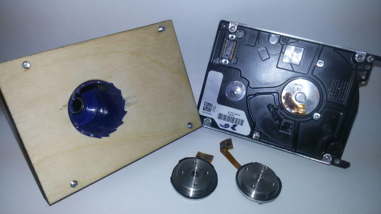
It remains the case for a small one - to get the motor from the HDD case, which by the way, in 2.5 disks (and in most 3.5) is its integral part. In short, the process can be described with the well-known phrase “ Saw, Shura, Saw! ”:

The outer metal crown guide is made of plywood and is attached to the body of the disc. For the safety of the motor cable is glued to its base, so as not to be cut by a crown
After drilling, we get roundels with a little motor. After processing the file, we obtain a base diameter of about 25mm.
Preparation of the recipient for transplantation:
The brains and heart of the future pump get along well with each other and are ready to find a new habitat. So it's time to think about the body and impeller.
Since it is necessary to obtain a high pressure with a small working volume, I designed the impeller with 7 rays:

Printing on a 3D polycarbonate printer
3D model
Polycarbonate - a great thing for the body. But typing a whole body is expensive for them. Pieces of thick sheets are very difficult to find and milling is not free (for me). But thanks to advertisers, you can ask for trimming from 4mm and 2mm thick sheets. So the body was designed for subsequent cutting with laser parts and gluing them together without the need for milling. Drilling holes for fittings and nuts will be required.
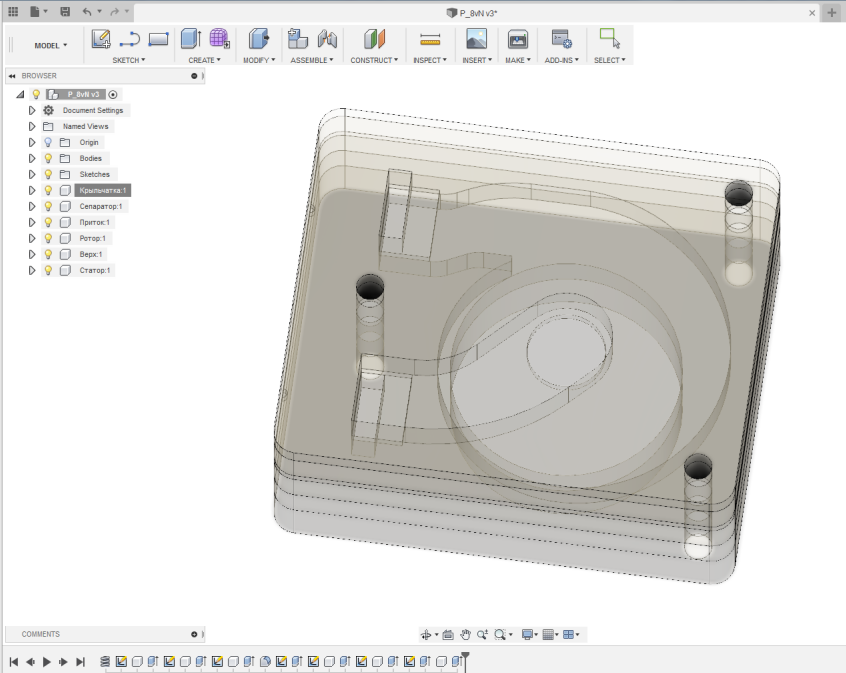
3D model view
3D model
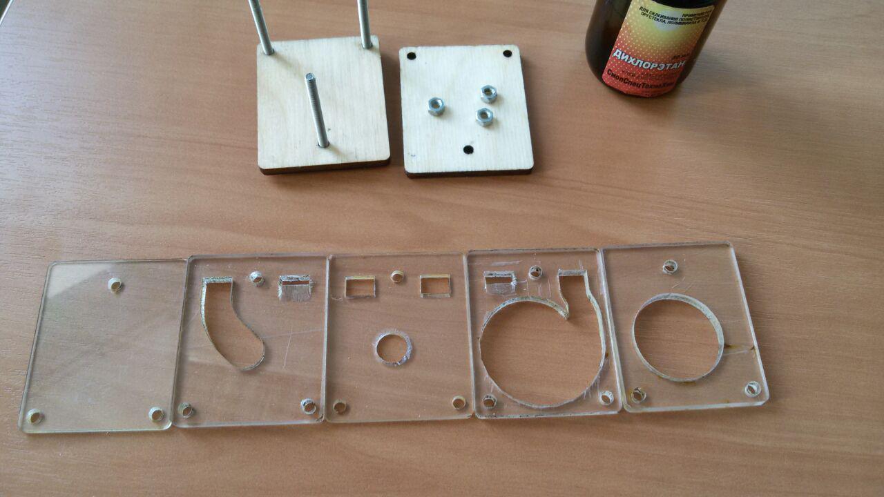
A set of parts for gluing "top" pump. The edges of the channels of inflow and outflow are cut off
The course of the operation:
Here I would like to make a digression and remind those who wish to repeat and not only that dichloroethane, which was glued together,
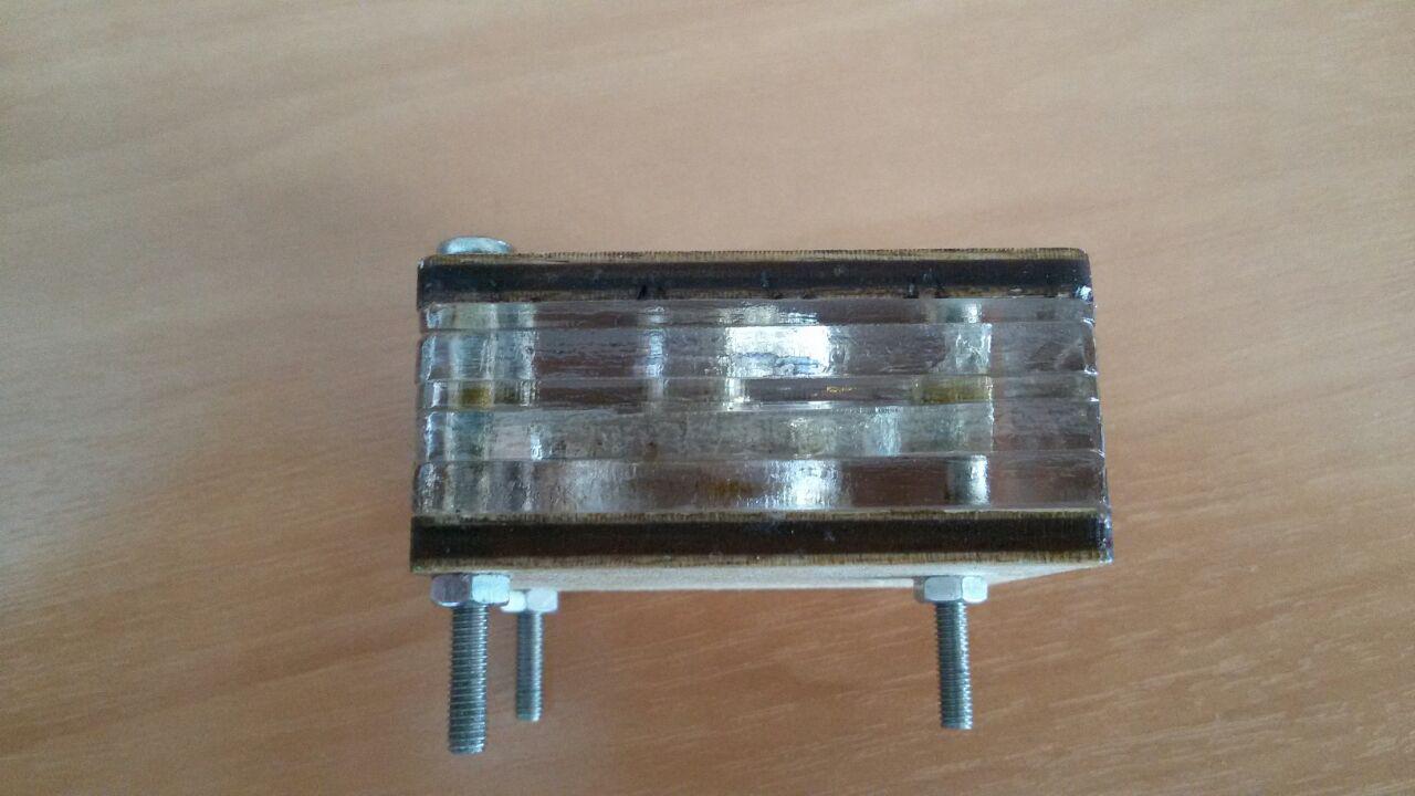
The stack of parts “top” on the drying after gluing - top-influx-separator-impeller-rotor. Similarly, the base is glued to the motor (or make a 6mm piece of polycarbonate entirely)
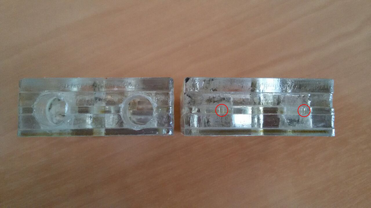
After gluing, holes are drilled for the fitting - 8mm brass tubing along the notches on the “separator” part
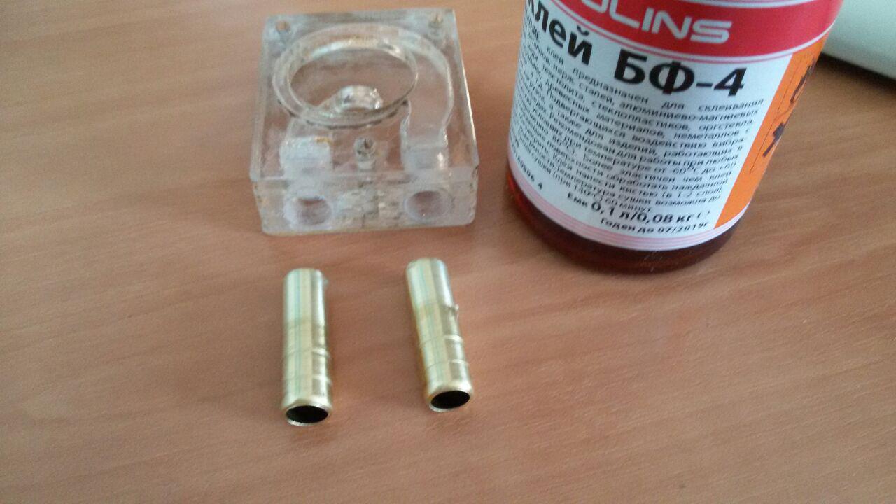
The good old composition of the BF-4 as for me gives a reliable gluing of brass and polycarbonate
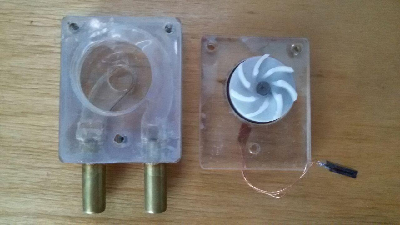
The same glue sticks the base of the motor to the bottom of the pump. In the upper part, holes are drilled out ( not through!) For inserting M3 rivet nuts. And the photo shows a thin silicone gasket.
Testing:
So it's time to check in the homemade work. For this, a test bench was quickly assembled. Since Habr is read by serious developers, whose appearance and composition of the stand can cause panic attacks, horror and disorientation, I wanted to hide it under the spoiler ... but I hope everything will work out, and then don’t say that I did not warn you, dear readers !

Arduinka sends a PWM control signal, the fill factor of which is set manually by a variable resistor, reads the value of the configuration registers, and also determines the rotation speed both through the internal driver registers (RPMrg) and the FG signal (RPMfg). Motor power - 12v
Starting the motor without load. Adjustment of turns and measurement of energy consumption
The motor starts successfully from 6% of the PWM control signal. And at the end of the video you can see how at high speeds the speed values in the internal register “hang” in the interval from 10k to 13k speed, although the frequency is fixed without changes through the FG output.
With idle, everything is clear - we got 13k turns at a voltage of 12v and a consumption of 0.16A. But a water pump was going to, and I'm driving the air here. So the next stage is escort of the household to the street, so as not to interfere, and the occupation of the bathroom!

Alas, I couldn’t make measurements and shoot video. So we will manage a photo of the general plan. To the measuring equipment added a stopwatch and a bank for 3l

According to the results of measurements, this table turned out

Consumption schedule
As a result - this hand-made article fully meets my requirements. And in the event of a breakdown, thanks to the collapsible design and the presence of crates with dead 2.5HDD in any repair shops / service centers, it will be easy to fix. And the path to the further construction of ITS is open! So to be continued!
Source: https://habr.com/ru/post/460070/
All Articles