To a question about a different or next cry of Yaroslavna
(Chinese) Chicken pecks on grain and it can be full.
For a start, I would like to complete the discussion on the cost of production of modules, initiated by the previous post. In the comments there was a link to a module similar to the one under consideration, with the striking difference that it was sold on Ali for an absolutely unbelievable amount of 58 rubles (I will not use the currency anymore, the original probably refers to yuan or US dollars, but in relation to the inhabitants of 1/8 of the land, the site kindly carries out the conversion). Considering the fact that in my post I determined the cost of the module at 300+ rubles, this price caused a slight shock (“and this is not a figure of speech denoting some incomprehensible garbage, but a very specific verb” - well, I really liked this expression of Divova).
PNP: KDPV to the second part of the crying.
However, there is an objective reality given to us in sensations, and this module at this particular price is a part of this reality, therefore, we assume that sensations do not deceive us and we will understand. In the description of the module, again kindly translated into Russian, the TL microcircuit is mentioned, on the basis of which the module was made and there is an example of a typical implementation in the datasheet (hereinafter) for this MSH, which does not contradict the photo of the module at all.
This is a specialized MCX for controlling the LED matrix, which contains:
')
- interface part for I2C with address programmable by feet,
- built-in generator and control circuit
- up to 8 keys of the lower arm,
- up to 12 upper arm current generators
- with setting the nominal current value by an external resistor and
- individual current adjustment for each element of the matrix.
I am a little naughty
The only question that you can ask MCh developers is: why line terminators are not included in the MCh, it seems to me that the implementation of a resistor and a capacitor of these nominal values should not be difficult. Yes, the terminator is needed only at the end of the line, but an additional leg, controlling the connection of it, solves this problem. And the presence directly on the board of additional elements of matching the transmission line, on the contrary, creates a problem, since the external circuit required to turn them off will entail redundant costs and is completely absent in the implementation under consideration. Moreover, an additional foot could choose one of two possible addresses. In principle, one can imagine a certain cascading scheme of modules (or mch) that would solve the problem of assigning addresses and connecting a terminator at the end of the chain (and automatic re-configuration when changing the composition of objects), but this topic clearly goes beyond my competencies (I’m not I design chips, and the TL firm does not write posts on Habr).
We are done with the circuitry, we turn to the economy and here everything is horribly simple and obvious:
- for definiteness, let us assume that the installation cost in the PRC is 1/2 of the corresponding figure in the Russian Federation (indicated after +), although this is not so important,
- the indicator, similar to CA56, on Ali costs 30 + 6 (against 130 in the distributor company from my last post + 12),
- mentioned mcx 6 + 5 (60 + 10),
- she just doesn't need current-limiting resistors 0 (8),
- 4 matching elements cost 2 (0),
- two capacitors have not gone away 1 (2),
- The cost of the board is 12 (10 boards for 2 dollars) against 28.
Total 36 + 11 + 2 + 1 + 12 = 62 - slightly more than the selling price for Ali, but still pretty close, making our assumptions and, significantly, five times less than 142 + 70 + 8 + 2 + 28 = 250 That is, being a Chinese entrepreneur, and buying components in the neighborhood, it is possible to sell modules at a price 10+ times less than a domestic manufacturer does. The only inconvenience for the buyer is the delivery time of 2+ weeks, which can be a determining factor in favor of import substitution for the electronics lover.
Crying begins
It remains an open question why the components cost exactly our distributor, that is, 5-10 times more expensive, and I absolutely firmly know that nothing of the module mentioned in the BOM (except for resistors and capacitors) is not produced in the Russian Federation and everything is purchased in the same PRC at prices not exceeding the prices of Ali. But, as I wrote earlier, I do not have a company of such magnitude as Platan, and I have no right to give advice and recommendations on pricing, I just express my bewilderment.
Well, the second part of the bewilderment lies in the price of components - why we cannot produce them at such a price - and I don’t need to talk about cheap labor - in the cost of the crystal, living labor is vanishingly small, the main contribution comes from depreciation of equipment, and I do not think China gets it at reduced prices.
PNP: It is by incomprehension and bewilderment that I differ from State Duma deputies and members of the Government of the Russian Federation who do not doubt for a second (absolutely no reason to doubt, but “this is my personal value judgment expressed in a private conversation”) that they understand absolutely everything and can set limits prices and allowances in various sectors of the economy. An indirect proof of the correctness of my value judgment is the brilliant situation in which the economy of the Russian Federation in general and electronics in particular are under such brilliant guidance.
The sun used to shine brighter and ...
Part two of the discussion of each will be devoted to one interesting crystal (I call the chips) manufactured by TI. In the blog of Jack Gansley, I treat him with great respect, there is a section “product of the month” in which he reviews interesting new items, and I decided to follow his example. It is not necessary at all that these will be new items, I just will describe them as they appear in my field of view.
Today's product is Seensor Tag 2, as always, from TI. Given the scale of acquisitions by this company of other manufacturers, soon all types of MCH will be included in its portfolio. On the one hand, I understand the threats stemming from the establishment of a monopoly, on the other hand, I cannot fail to recognize the convenience created by the monopoly. In any case, no one was interested in my opinion before the merger of TI and the National Assembly, and therefore I categorically refuse to be responsible for any negative consequences of this event and do not pretend to have any positive consequences, but simply inform about those and others.
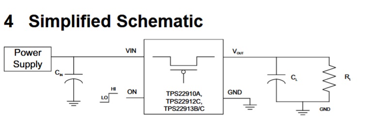
The module itself is very interesting, I ordered a couple and after receiving them I will give a detailed analysis, because I prefer to rely on my own impressions and test results, rather than press releases from the marketing department (I know their habit of not agreeing, and on a threatening scale). In the meantime, I looked at the diagram of the module, kindly presented in the technical documentation section and drew attention to one of the components installed on it - TPS22910, then you can follow the date at the link www.ti.com/lit/ds/symlink/tps22913.pdf
Briefly about the chip
This is just a key for a very limited current of 2 A and a voltage of not more than 5.5 V - it would seem, what is there to talk about, take any field player and enjoy. But the devil, as you know, is in the details and here they are:
- The minimum switching voltage is 1.5V with a pass resistance of 80 mΩ - not every field-effect transistor will show such results,
- “Logical” and unchanging switching control threshold at any switching voltage,
- built-in reverse current protection
- Built-in undervoltage protection
- guaranteed (and quite good) switching timing,
- small case (I, in general, according to FIG, but the manufacturer emphasizes this fact).
I hope I praised this device enough that the following statements would not seem to be a hit (and they will follow, which of my readers would doubt).
PNP: Interestingly, if there were flaws, I would write about this MSC - a question, rather, a rhetorical one, but it makes me think about my motivations for creativity. When another interesting crystal with perfectly written documentation comes into my hands, then much will become clear.
But I did not understand this
There are only four legs on the microcircuit - input, output, ground and control - which is much simpler. So, I look at the circuit board, there is a pull-up resistor to the ground on the switch-on leg, the MSH is quite obviously including, I open the date to make sure that this is indeed the case, and I watch a completely adorable picture. In step 4, a step is depicted near the control legs (recently this style has become popular, although personally it seems to me that the truth table is more informative and does not give room for interpretation) and on this step they usually write on / off (dis / en), but in This particular case is written LO / HI. Thank you, captain, but I did not understand what level connects the entrance with the exit.
The functional diagram in section 10.2 did not bring clarity, since the control foot is included in a box called Control Logic, and it can do anything. Section 10.3.1 once again tells us that this leg controls the state of the key and again does not say a word how.
Scrolling the date further - in the parameter table (section 8.3) for the control signal the value of low level (0.6V) and high (1.1V) is indicated - control from MK with any reasonable power is really possible. In addition, in section 8.5, the current (1 μA) is indicated, which is necessary for the formation of the required level at the control stem - quite suitable for the MK with any reasonably designed pins. True, for some reason, the current is given with only one sign (probably, an absolute value is meant) and for voltage values higher than 1.5V or exactly 0V (that is, nothing is guaranteed at operating values — funny). A little further, in the description of the work (section 11.1.2), it is said about the need to maintain the level and the inadmissibility of the "floating" input, but again not a word about the level of inclusion.
Further up to date - in section 9 a picture of the on / off delay measurement technique is presented, supplied with the same picture with a step (and the same signatures) and it is absolutely clear from it that the output is turned to high level on the control. An indirect confirmation of this hypothesis is that the name of the control input is given without overlining, underlining, and also ~ or #, which are usually supplied with inverse inputs. But what about the scheme where the mch is turned on by a clearly low level - we continue the investigation.
At the very end of the date (section 11.2.3.1), the oscillograms are given that give an idea of the dynamic parameters of the MCC (they give an idea, in no way can they be guided as a source of data, for this there are tables with explicit indication of parameters) and it is clear that the resolution level is still low. But why nowhere is this explicitly indicated - we look at the date further and find another set of oscillograms (section 11.2.3.2) in which the mch is turned on at a high level. And here comes the solution to the quest - there are four types of MCCs in the family (22910A, 22912C, 22913B, 22193), which are distinguished not only by the load capacity, but also by the level of inclusion, and the date is common to all. For option A, the active level is low, and for the remaining three - high.
That's what it was
It turns out that on page 3 the date in section 6 is a table of differences between the performances, in the last column of which this feature is clearly indicated, but who carefully looks at the content of such tables - that’s what I didn’t look at. Let’s leave behind the reason for the decision to make different levels of inclusion for different options, I don’t presume to guess it, I guess so. But we must pay tribute to the developers of the documentation - they honestly reported on this particular feature of the MSC, I just was not attentive enough. Moreover, the heading of the table with parameters in section 8.5 clearly indicates the on and off levels for different versions of the MCCs, which I also did not pay enough attention to (I’ve been used to looking at the bottom of the parameter tables for a long time, but I missed the heading).
PNP: I immediately remembered MSH 1401UD2, which had a power layout of -4 + 11 in a plastic case (K), and 4-11 in a metal-ceramic (CD) + 4-11, which was a particular joy for developers. Fortunately, the layout of the remaining legs made it easy to deploy the case (such as DIP16) and get a working board. So, not only foreign manufacturers can successfully joke (fun to pin up).
Plate "Sarcasm"
Well, after I sprinkled ashes enough on my head and confessed to the sin of inattention, let me predict that if the figure in section 4 next to the step read "see Table 6" or there was a link to a similar note, then no claims to the developers were not in principle (probably ... "I think so").
PNP: looked at the date from several manufacturers and found discrete P-channel transistors with similar parameters (resistance not more than 88 mΩ when the gate voltage is -1.5V). I wonder how they achieve this, my knowledge from the course "Technology of production of electronic devices" to answer this question is not enough, but it would be interesting ...
Source: https://habr.com/ru/post/459384/
All Articles