A little about the standards of space communications

Satellite Meteor M1
Source: vladtime.ru
Introduction
Operation of space technology is impossible without radio communications, and in this article I will try to explain the main ideas that formed the foundation of the standards developed by the International Space Data Systems Advisory Committee (CCSDS. This abbreviation will be used later).
This publication will be devoted mainly to the channel level, but the basic concepts for other levels will also be introduced. This is by no means a claim for a thorough and complete description of the standards. You can find him on the CCSDS website . However, they are very difficult for perception, and in order to understand them we spent a lot of time, so here I want to give basic information, having which to deal with everything else will be much easier. So, let's begin.
The noble mission of CCSDS
Perhaps someone has a question: why should everyone stick to the standards if they can develop their own proprietary stack of radio communications protocols (or their standard, with blackjack and new features), thereby increasing the security of the system?
')
As practice shows, it is more profitable to adhere to the CCSDS standards for the following several reasons:
- The committee responsible for publishing standards included representatives from all the major aerospace agencies of the world, bringing in their invaluable experience gained over many years of designing and operating various missions. It would be very absurd to ignore this experience and to step on their rake again.
- These standards are supported by the ground station equipment already on the market.
- In the course of troubleshooting any problems, you can always ask for help from colleagues from other agencies so that they can hold a communication session with the device from their ground station.
Architecture
Standards are a collection of documents that reflect the most common OSI (Open System Interconnection) model, except that at the channel level, generality is limited to the division into telemetry (channel “down” - space - Earth) and telecommand (channel “up”).
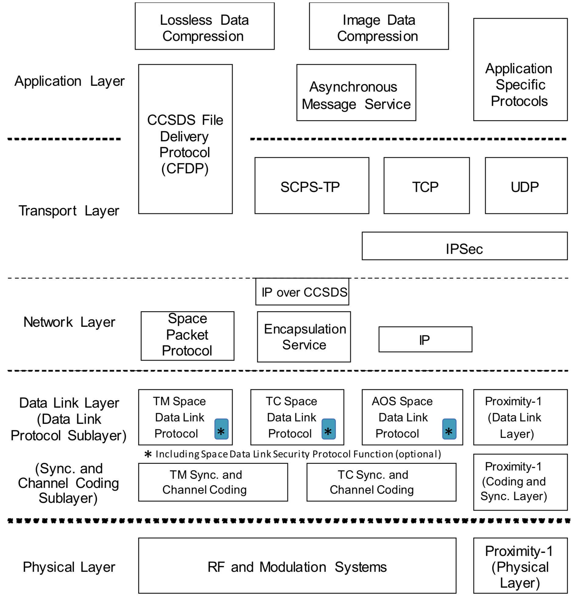
Consider some levels in more detail, starting with the physical, and moving up. For greater clarity, we consider the architecture of the host country. Transmitter is its mirror image.
Physical level
At this level, the modulated radio signal is converted into a bitstream. The standards here are mainly of a recommendatory nature, since at this level it is difficult to ignore the concrete implementation of iron. Here, the key role of CCSDS is to determine the allowable modulations (BPSK, QPSK, 8-QAM, etc.) and to give some recommendations on the implementation of symbolic synchronization mechanisms, Doppler shift compensation, etc.
Sync and coding level
Formally, it is a sublayer of the data link layer, however, it is often allocated to a separate level due to its importance within the framework of the CCSDS standards. This level converts the bitstream into so-called frames (telemetry or telecommand), which we will talk about later. In contrast to the symbolic synchronization at the physical level, which allows you to get the correct bitstream, frame synchronization is performed here. Consider the path that data travels at this level (bottom to top):

However, before this is to say a few words about coding. This procedure is necessary to find and / or correct bit errors that inevitably occur when sending data over the air. Here we will not consider decoding procedures, but only obtain the information necessary for understanding the further logic of the level operation.
Codes are block and continuous. Standards do not force the use of a specific type of encoding, but it should be present as such. Continuous are convolutional (colvolutional) codes. By means of them the continuous bit stream is encoded. Unlike block codes, where data is divided into code blocks (codeblock), and can only be decoded within solid blocks. The code block is the transmitted data and the attached redundant information necessary to verify the correctness of the data received and correct possible errors. Block codes include the famous Reed-Solomon codes.
If convolutional coding is used, the bitstream from the beginning goes to the decoder. The result of his work (all this, of course, is happening continuously) are CADU (channel access data unit) data blocks. This structure is required for frame synchronization. At the end of each CADU is attached sync marker (ASM - attached synch maker). These are 4 bytes known in advance, on which the synchronizer finds the beginning and the end of the CADU. This is how frame synchronization is achieved.
The next optional stage of the synchronization and coding level is associated with the features of the physical layer. This is derandomization. The fact is that in order to achieve symbolic synchronization, frequent switching between symbols is necessary. So, if we transmit, say, kilobytes of data consisting entirely of ones, the synchronization will be lost. Therefore, during transmission, the input data is mixed with a periodic pseudo-random sequence so that the density of zeros and ones is uniform.
Next comes the decoding of block codes, and what remains is the final product of the synchronization and coding level — the frame.
Link level
On the one hand, the data link layer handler receives frames, and on the other hand, it issues packets. Since formally the size of the packets is not limited, for their reliable forwarding it is necessary to break them into smaller structures - frames. Here we consider two subsections: separately for telemetry (TM) and telecommand (TC).
Telemetry
Simply put, this is the data that the ground station receives from the spacecraft. All transmitted information is divided into small fragments of fixed length - frames, which contain the transmitted data and service fields. Consider the frame structure in more detail:
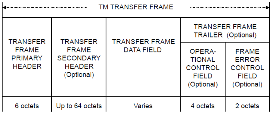
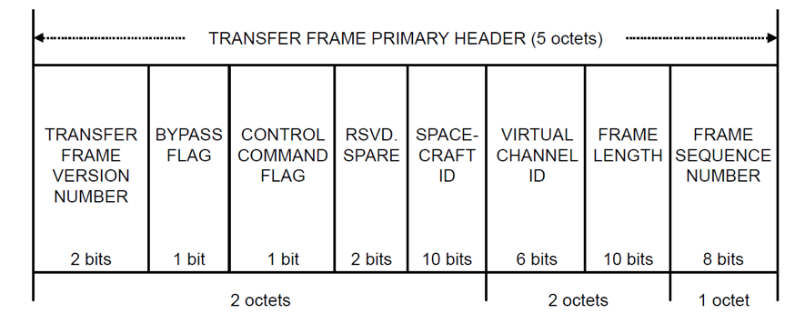
And we will begin consideration with the main header of the telemetry frame. Next, let me in some places just translate standards, along the way giving some explanations.

The Master Channel ID field must contain the frame version number and the device ID.
Each spacecraft, according to the CCSDS standards, should have its own unique identifier, by which it is possible, having a frame, to determine which device it belongs to. Formally, it is necessary to submit an application for registration of the device, and its name, together with the identifier, will be published in open sources. However, Russian manufacturers often ignore this procedure, assigning an arbitrary identifier to the device. The version number of the frame helps determine which version of standards is used to correctly read the frame. Here we consider only the most conservative standard with version "0".
The Virtual Channel ID field must contain the VCID of the channel from which the packet came. There are no restrictions on the choice of VCID, in particular, virtual channels are not necessarily numbered sequentially.
Very often there is a need to multiplex the transmitted data. For this there is a mechanism for virtual channels. For example, the Meteor-M2 satellite transmits a color image in the visible range, dividing it into three black and white - each color is transmitted in its virtual channel as a separate packet, although there is some deviation from the standards in the structure of its frames.
The Operational Control flag field shall be an indicator of the presence or absence of an Operational Control field in a telemetry frame. These 4 bytes at the end of a frame serve to maintain feedback while monitoring the delivery of frames of telecommands. We will talk about them later.
Frame counters of the main and virtual channels are fields incremented by one when sending each frame. Serve as an indicator that no frames were lost.
The status of telemetry frame data is two more bytes of flags and data, of which we will consider only a few.
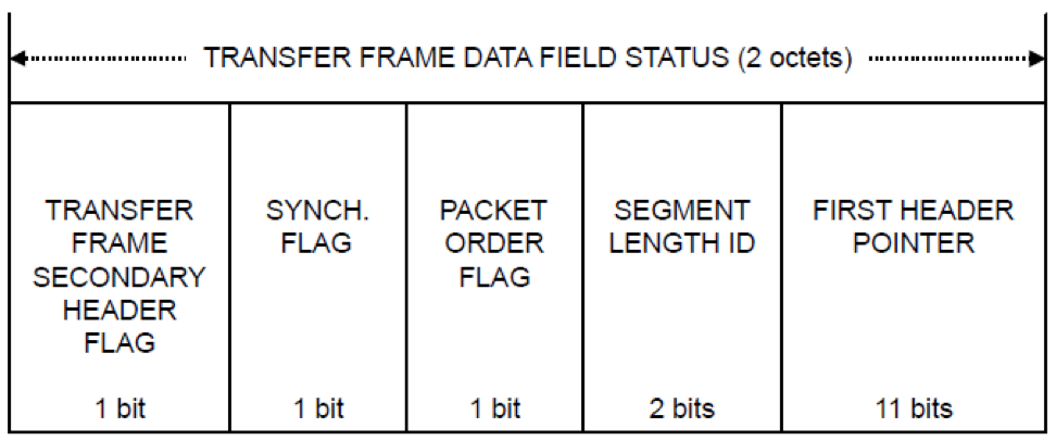
The Secondary Header flag field should be an indicator of the presence or absence of the Secondary Header in the telemetry frame.
If you wish, you can add an additional header to each frame and place any data there at your discretion.
The pointer field to the first header (First Header Pointer), with the synchronization flag set to "1", should contain the binary representation of the position of the first octet of the first Packet in the Data Field field of the telemetry frame. The position is counted from 0 in ascending order from the beginning of the data field. If there is no packet start in the telemetry frame data field, then the pointer field to the first header should have a value in the binary representation of “11111111111” (this can happen if one long packet extends over more than one frame).
If the data field contains an empty packet (Idle Data), then the pointer to the first header should have a value in the binary representation "11111111110". For this field, the receiver must synchronize the flow. This field guarantees synchronization recovery even in case of frame skipping.
That is, a packet may, suppose, begin in the middle of the 4th frame, and end at the beginning of the 20th. To find its beginning, this field serves just as it should. Packets also have a header, in which its length is written, so when the pointer to the first header is found, the channel level handler must read it, thereby determining where the packet will end.
If an error control field is present, it must be contained in each telemetry frame for a particular physical channel throughout the mission.
This field is calculated using the CRC method. The procedure should take n-16 bits of the telemetry frame and insert the result of the calculation in the last 16 bits.
Telecommand
Frame telecommand has several significant differences. Among them:
- Other header structure
- Dynamic length This means that the frame length is not specified rigidly, as is done in telemetry, but may vary depending on the transmitted packets.
- Package guarantee mechanism. That is, the AC should, upon receipt, confirm the correct reception of frames, or request a transfer from the frame that could be received with an uncorrectable error.

Many fields are already familiar to us from the header of the telemetry frame. They have the same purpose, so here we consider only new fields.
One bit of the bypass flag should be used to control frame checking on the receiver. The value “0” of this flag should indicate that this frame is a type A frame and should be checked according to FARM. The value “1” of this flag should indicate to the receiver that this frame is a type B frame and should bypass the FARM check.
This flag informs the receiver whether it is necessary to use the frame delivery confirmation mechanism called FARM - Frame Acceptance and Reporting Mechanism.
The control command flag should be used to understand whether the data field transports a command or data. If the flag is "0", then the data field should contain data. If the flag is “1”, then the data field should contain control information for FARM.
FARM is a state machine whose parameters can be configured.
RSVD. SPARE - reserved bits.
It seems that CCSDS has plans for them in the future, and for backward compatibility of protocol versions they reserved these bits already in the current versions of the standard.
The frame length field must contain a number in the bit representation that is equal to the frame length in octets minus one.
The frame data field shall follow the header without gaps and contain an integer number of octets, which may be a maximum of 1019 octets. This field should contain either a block of frame data or control command information. The frame data block must contain:
- integer octets of user data
- segment header and following integer octets of user data
If the header is present, then the data block must contain the Package, the set of Packages, or part of it. A data block without a header may not contain parts of the Packet, but may contain data blocks of a private format. From this it follows that the header is required when the transmitted data block does not fit in one frame. A data block with a header is called a segment.
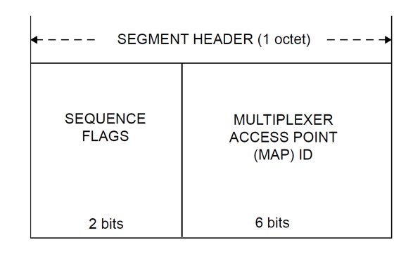
The two-bit flag field should contain:
- "01" - if the first part of the data is in the data block
- “00” - if the middle part of the data is in the data block
- "10" - if the last part of the data is in the data block
- “11” - if there is no division and in the data block one or several packages are placed entirely.
The MAP ID field must be zero if MAP channels are not used.
Sometimes 6 bits allocated for virtual channels is not enough. And if it is necessary to multiplex data on a larger number of channels, 6 more bits from the segment header are used in the course.
FARM
Let us consider in more detail the mechanism of functioning of the delivery control system This system provides only for work with telecommand personnel because of their importance (telemetry can always be requested again, and the spacecraft should hear the ground station clearly, and always obey its commands). So, suppose we decided to reflash our satellite, and send a binary file of 10 kilobytes on board. At the link level, the file is divided into 10 frames (0, 1, ..., 9), which are sent upward in turn. When the transmission is completed, the AC must confirm the correctness of the packet reception, or report on which frame the error occurred. This information is sent to the field of operational control in the nearest telemetry frame (Or, the AC can initiate the transfer of an empty frame (idle frame) if it has nothing to say). On the received telemetry, we either make sure that everything is fine, or proceed to resend the message. Suppose the satellite has not heard the frame number 7. So, we send him frames 7, 8, 9. In the event that there is no answer, the packet is sent entirely once again (and so several times, until we realize that the attempts are futile).
Below is the structure of the field of operational control with a description of some fields. The data contained in this field is called CLCW - Communication Link Control Word.

Since the picture is quite possible to guess the purpose of the main fields, and the others look boring, I hide the detailed description under the spoiler
CLCW field decoding
Control Word Type:
For this type of control word must contain 0
Control Word Version (CLCW Version Number):
For this type of control word, the value must be “00” in the bit representation.
Status Field:
The use of this field is determined for each mission separately. Can be used for local enhancements by various space agencies.
Virtual Channel Identification:
It must contain the identifier of the virtual channel with which this control word is associated.
Physical channel access flag:
The flag should provide information on the readiness of the physical level of the receiver. If the physical level of the receiver is not ready to receive frames, then the field must contain “1”, otherwise “0”.
Sync failed flag:
The flag may indicate that the physical layer works when the signal level is bad and the number of frames rejected is too high. The use of this field is optional, if used, it must contain “0” in the presence of synchronization, and “1” in its absence.
Lock flag:
This bit must contain the FARM lock status for each virtual channel. The value “1” in this field should indicate that the FARM is blocked and frames will be discarded for each virtual layer, otherwise “0”.
Waiting Flag:
This bit should be used to indicate that the receiver cannot process the data on the specified virtual channel. The value “1” indicates that all frames will be discarded on this virtual channel, otherwise “0”.
Re-send flag:
This flag should contain “1” if one or more type A frames were dropped or gaps were found, so re-sending is necessary. The “0” flag indicates that there were no dropped frames and gaps.
Answer value:
Frame number that was not accepted. Determined by the counter in the frame header of the telecommand
Network layer
A little touch on this level. There are two possible options: either use the space packet protocol or encapsulate any other protocol in the CCSDS packet.
A review of the space package protocol is a topic for a separate article. It is designed so that so-called applications can exchange data seamlessly. Each application has its own address, and basic functionality for communicating with other applications. There are also services that perform traffic routing, perform delivery control, etc.
With encapsulation, everything is simpler and clearer. Standards make it possible to encapsulate any protocols in CCSDS by adding an additional header.
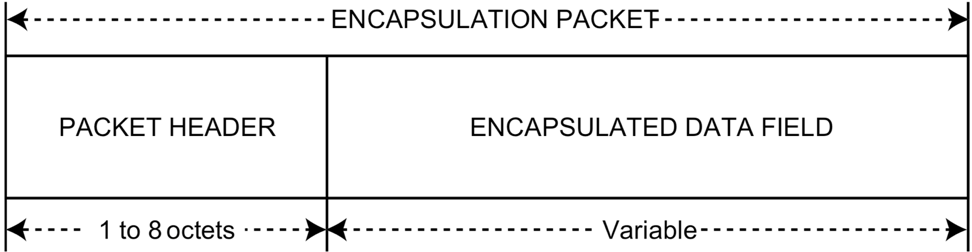
Where the header has different meanings depending on the length of the encapsulated protocol:

Here the main field is the length of the length. It can vary from 0 to 4 bytes. Also in this header you need to specify the type of the encapsulated protocol, using the table from here .
When IP is encapsulated, another add-on is used to determine the type of packet.
It is necessary to add one more header, one octet in length:
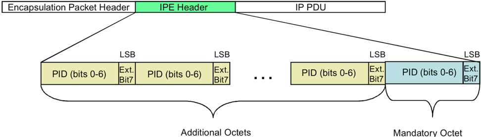
Where PID is another protocol identifier taken from here.
Conclusion
At first glance it may seem that the CCSDS headers are extremely redundant, and some fields could be discarded. Indeed, the effectiveness of the resulting channel (up to the network level) is about 40%. However, as soon as it becomes necessary to implement these standards, it becomes clear that each field, each header has its own important mission, ignoring of which leads to a number of ambiguities.
If habrabschestvuy interest in this topic, I will be glad to publish a number of articles devoted to the theory and practice of space communications. Thanks for attention!
Sources
CCSDS 130.0-G-3 - Overview of the space communications protocols
CCSDS 131.0-B-2 - TM synchronization and channel coding
CCSDS 132.0-B-2 - TM Space Data Link Protocol
CCSDS 133.0-B-1 - Space packet protocol
CCSDS 133.1-B-2 - Encapsulation Service
CCSDS 231.0-B-3 - TC Synchronization and Channel Coding
CCSDS 232.1-B-2 Communications Operation Procedure-1
CCSDS 401.0-B-28 Radio Frequency and Modulation Systems - Earth Stations and Spacecraft
CCSDS 702.1-B-1 - IP over CCSDS space links
PS
Do not hit hard if you find inaccuracies. Report them and they will be corrected :)
Source: https://habr.com/ru/post/458884/
All Articles