Training Cisco 200-125 CCNA v3.0. Day 11. VLAN Basics
Before we get to the basics of VLAN, I would ask all of you to pause this video, click on the icon in the lower left corner, where the Networking consultant is written, go to our Facebook page and like it. Then go back to the video and click on the King icon in the bottom right corner to subscribe to our official YouTube channel. We are constantly adding new series, now it concerns the CCNA course, then we plan to start the CCNA Security, Network +, PMP, ITIL, Prince2 video tutorial course and publish these wonderful series on our channel.
So, today we will talk about the basics of VLAN and answer 3 questions: what is VLAN, why do we need VLAN and how to configure it. I hope that after watching this video you can answer all three questions.
What is a VLAN? VLAN is an abbreviation of the name “virtual local area network”. Further down the course of our lesson, we will look at why this network is virtual, but before we go to the VLAN, we need to understand how the switch works. We will repeat some of the questions that were discussed in previous lessons.
')
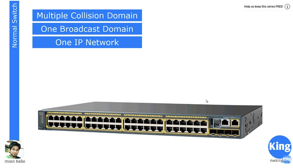
We first discuss what constitutes a Multiple Collision Domain, or a collision domain. We know that this 48-port switch has 48 collision domains. This means that each of these ports or devices connected to these ports can interact with another device on another port independently, without affecting each other.
All 48 ports of this switch are part of the same broadcast domain Broadcast Domain. This means that if several devices are connected to several ports, and one of them is broadcasting, it will appear on all ports to which other devices are connected. This is how the switch works.
It is as if people were sitting in one room close to each other, and when one of them says something loudly, everyone else hears it. However, this is completely ineffective - the more people will appear in the room, the noisier it will become and those present will no longer hear each other. A similar situation arises with computers - the more devices are connected to the same network, the greater the “loudness” of the broadcasting becomes, which makes it impossible to establish an effective connection.
We know that if one of these devices is connected to the 192.168.1.0/24 network, all other devices are part of the same network. The switch must also be connected to the network with the same IP address. But here the switch as a device OSI level 2 may have a problem. If two devices are connected to the same network, they can easily connect to each other’s computers. Suppose that in our company there is a “bad guy”, a hacker, whom I will draw on top. Below it is my computer. So, this hacker is very easy to get into my computer, because our computers are part of the same network. That is the problem.
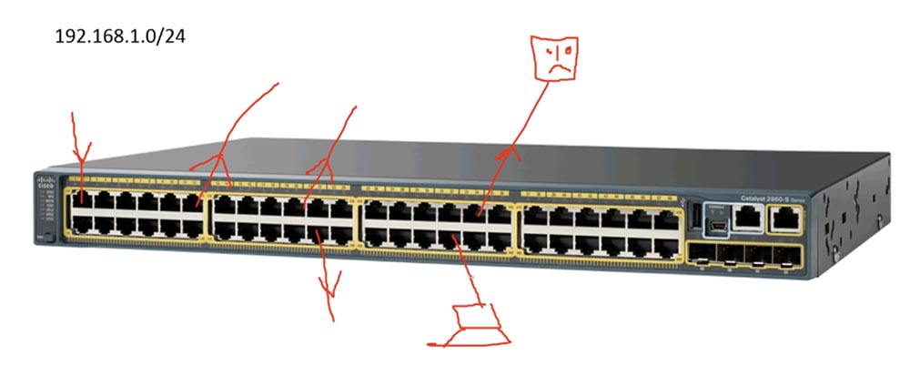
If I belong to the executive management, and this new guy will be able to access files on my computer, it will not be good at all. Of course, there is a firewall on my computer that protects against many threats, but a hacker will not be able to bypass it.
The second danger that exists for all who are members of this broadcast domain is that if someone has a broadcast problem, this interference will affect other devices on the network. Although all 48 ports can be connected to different hosts, the failure of one host will affect the other 47, which we do not need at all.
To solve this problem, we use the concept of VLAN, or VLAN. It works very simply, dividing this one big 48-port switch into several smaller switches.
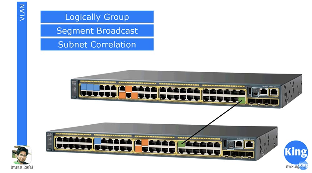
We know that subnets divide one large network into several small networks, and VLAN works in a similar way. It divides the 48 – and port switch, for example, into 4 switches with 12 ports, each of which is part of a new interconnected network. At the same time, we can use 12 ports for management, 12 ports for IP-telephony and so on, that is, to divide the switch not physically, but logically, virtually.
I selected three ports of the upper switch, marked in blue, for the “blue” VLAN10 network, and I assigned three orange ports to VLAN20. Thus, any traffic from one of these blue ports will flow only to the other blue ports, without affecting the other ports of this switch. Traffic from the orange ports will be distributed in the same way, that is, we are supposed to use two different physical switches. Thus, VLAN is a way of splitting a switch into several switches for different networks.
I drew two switches from above, here we have a situation where only the blue ports for one network are involved on the left switch, and only orange for the other network on the right switch, and these switches are in no way connected to each other.
Let's say you go to use more ports. Imagine that we have 2 buildings, each of which has its own management staff, and two orange ports of the lower switch are used for management. Therefore, we need these ports to be connected to all the orange ports of other switches. The situation is similar with blue ports - all blue ports of the upper switch must be connected to other ports of the same color. To do this, we need to physically link these two switches in different buildings with a separate communication line; in the figure this is the line between the two ports in green. As we know, if two switches are physically connected, we will have a trunk, or trunk.
What is the difference between a normal and VLAN switch? This is not a big difference. When you buy a new switch, by default all ports are configured for VLAN mode and are part of the same network, denoted as VLAN1. That's why when we connect a device to one port, it is connected to all other ports, because all 48 ports belong to the same virtual network VLAN1. But if we configure the blue ports to work on the VLAN10 network, the orange ports on the VLAN20 network, and the green ports on the VLAN1 network, we will get 3 different switches. Thus, the use of the virtual network mode allows us to logically group ports for specific networks, divide the broadcast into parts and create subnets. In addition, each of the ports of a particular color belongs to a separate network. If the blue ports work on the 192.168.1.0 network and the orange ports work on the 192.168.1.0 network, in spite of the same IP address, they will not be connected to each other, because they will logically belong to different switches. And as we know, different physical switches do not communicate with each other unless they are connected by a common line of communication. Thus, we create different subnets for different VLANs.
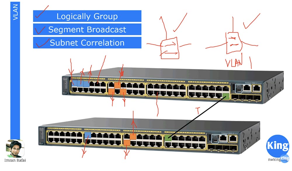
I want to draw your attention that the concept of VLAN applies only to switches. Anyone familiar with encapsulation protocols, such as .1Q or ISL, knows that neither routers nor computers have any VLANs. When you connect your computer, for example, to one of the blue ports, you do not change anything in the computer, all changes occur only at the second level of OSI, the switch level. When we configure ports to work with a specific VLAN10 or VLAN20 network, the switch creates a VLAN database. It “writes” to itself in memory that ports 1,3 and 5 belong to VLAN10, 14,15 and 18 ports are part of the VLAN20 network, and the other ports involved are parts of the VLAN1 network. Therefore, if some traffic originates from blue port 1, it only hits ports 3 and 5 of the same VLAN10 network. The switch “looks” into its database and sees that if traffic comes from one of the orange ports, it should only go to the orange ports of the VLAN20 network.
However, the computer does not know anything about these VLANs. When we connect 2 switches, a trunk is formed between the green ports. The term “trunk” is relevant only for Cisco devices, the rest of network device manufacturers, such as Juniper, use the term Tag port, or “tagged port”. I think the name Tag port is more appropriate. When traffic flows from this network, the trunk transmits it to all ports of the next switch, that is, we connect two 48-port switches and receive one 96-port switch. At the same time, when we send traffic from VLAN10, it becomes tagged, that is, supplied with a label that indicates that it is intended only for VLAN10 ports. The second switch, having received this traffic, reads the tag and understands that this traffic is for VLAN10 and should only go to the blue ports. Similarly, the “orange” traffic for VLAN20 is provided with a tag that indicates that it is intended for VLAN20 ports of the second switch.
We also mentioned encapsulation, and there are two encapsulation methods here. The first is .1Q, that is, when we organize a trunk, we need to provide encapsulation. The encapsulation protocol .1Q is an open standard describing the traffic tagging procedure. There is another protocol called ISL, the Inter-Switch link, developed by Cisco, which indicates that a particular VLAN is belonging to traffic. All modern switches work with the .1Q protocol, therefore, taking a new switch out of the box, you do not need to use any encapsulation commands, because by default it is implemented by the .1Q protocol. Thus, after creating a trunk, traffic is automatically encapsulated, which allows you to read tags.
Now let's get down to setting up a VLAN. Let's create a network in which there will be 2 switches and two end devices - computers PC1 and PC2, which we will connect with cables with switch # 0. Let's start with the basic settings of the Basic Configuration switch.

To do this, click on the switch and go to the command line interface, and then set the host name, naming this switch sw1. Now let's move to the settings of the first computer and set the static IP address 192.168.1.1 and the subnet mask 255.255. 255.0. The default gateway address is not needed, because all our devices are on the same network. Next, we will do the same for the second computer, assigning it the IP address 192.168.1.2.
Now back to the first computer to ping the second computer. As you can see, pinging went well because both of these computers are connected to the same switch and are part of the same network by default VLAN1. If you look at the switch interfaces now, we will see that all FastEthernet ports from 1 to 24 and two GigabitEthernet ports are configured for VLAN # 1. However, such excessive availability is not needed, so we enter the switch settings and enter the show vlan command to look at the virtual network database.
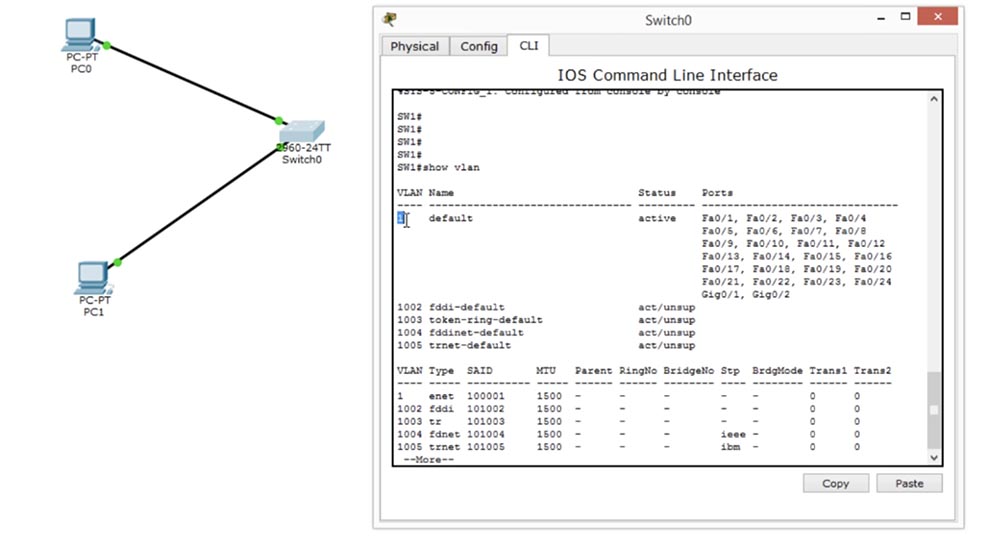
You see here the name of the VLAN1 network and the fact that all ports of the switch belong to this network. This means that you can connect to any port, and all of them will be able to “communicate” with each other, because they are part of the same network.
We will change this situation, for this we first create two virtual networks, that is, add VLAN10. To create a virtual network, use the “vlan network number” command.
As you can see, when trying to create a network, the system issued a message listing the VLAN configuration commands that should be used for this action:
exit - apply changes and exit settings;
name — enter a custom VLAN name;
no - cancel the command or set it as default.
This means that before you enter the command to create a VLAN, you must enter the command name, which includes the name management mode, and then proceed to create a new network. In this case, the system prompts that the VLAN number can be assigned in the range from 1 to 1005.
So, now we enter the command to create a VLAN at number 20 - vlan 20, and then give it a name for the user, which shows what kind of network it is. In our case, we use the name Employees command, or the network for company employees.

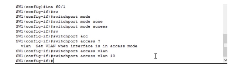
Now we need to assign a specific port to this VLAN. We enter the int f0 / 1 switch settings mode, then manually switch the port to Access mode using the switchport mode access command and specify which port to switch to this mode — this is the port for the VLAN10 network.
We see that after this, the color of the PC0 junction point and the switch, the port color, changed from green to orange. It will turn green again as soon as the settings change takes effect. Let's try to ping the second computer. We did not make any changes to the network settings for computers; they still have the IP addresses 192.168.1.1 and 192.168.1.2. But if we try to ping PC1 from PC0, we will fail because now these computers belong to different networks: the first is to VLAN10, the second is to native VLAN1.
Let's go back to the switch interface and configure the second port. To do this, I will enter the int f0 / 2 command and repeat for VLAN 20 the same steps as for setting up the previous virtual network.
We see that now the lower port of the switch, to which the second computer is connected, also changed its color from green to orange - it takes several seconds before the changes in the settings take effect and it turns green again. If you ping the second computer again, it will not work, because the computers still belong to different networks, only PC1 is now not part of VLAN1, but VLAN20.
Thus, you have divided one physical switch into two different logical switches. You see that now the color of the port has changed from orange to green, the port is working, but it still does not ping because it belongs to another network.
Let's make changes to our scheme - disconnect PC1 from the first switch and connect it to the second switch, and connect the switches themselves with a cable.

In order to establish a connection between them, I will enter the settings of the second switch and create VLAN10, giving it the name Management, that is, the management network. Then I turn on Access mode and indicate that this mode is for VLAN10. Now the color of the ports through which the switches are connected has changed from orange to green because they are both configured for VLAN10. Now we need to create a trunk between both switches. Both of these ports are Fa0 / 2, so you need to create a trunk for the Fa0 / 2 port of the first switch using the switchport mode trunk command. The same must be done for the second switch, after which a trunk is formed between these two ports.
Now, if I want to ping PC1 from the first computer, everything will work out, because the connection between PC0 and switch # 0 is VLAN10, between switch # 1 and PC1 is also VLAN10, and both switches are connected by a trunk.
So, if the devices are located in different VLANs, then they are not connected to each other, and if in the same network, then free traffic can be exchanged between them. Let's try to add one more device to each switch.
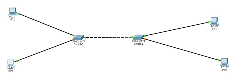
In the network settings of the added PC2 computer, I will set the IP address to 192.168.2.1, and in the PC3 settings to the address 192.168.2.2. In this case, the ports to which these two PCs are connected will receive the designation Fa0 / 3. In the settings of the switch # 0 we set the Access mode and indicate that this port is for VLAN20, and do the same for switch # 1.
If I use the switchport access vlan 20 command, and the VLAN20 network has not yet been created, the system will generate an error like “Access VLAN does not exist”, because the switches are configured to work only with VLAN10.
Let's create VLAN20. I use the "show VLAN" command to view the virtual network database.
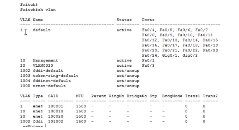
You can see that the default network is VLAN1, to which ports from Fa0 / 4 to Fa0 / 24 and Gig0 / 1, Gig0 / 2 are connected. Virtual network number 10 with the name Management is connected to port Fa0 / 1, and VLAN network number 20 with the default name VLAN0020 is connected to port Fa0 / 3.
In principle, the name of the network does not matter, as long as it does not repeat for different networks. If I want to replace the default network name that the system assigns, I use the command vlan 20 and name Employees. I can change this name to another, for example, to IPphones, and if we ping the IP address 192.168.2.2, we will see that the name of the VLAN does not matter.
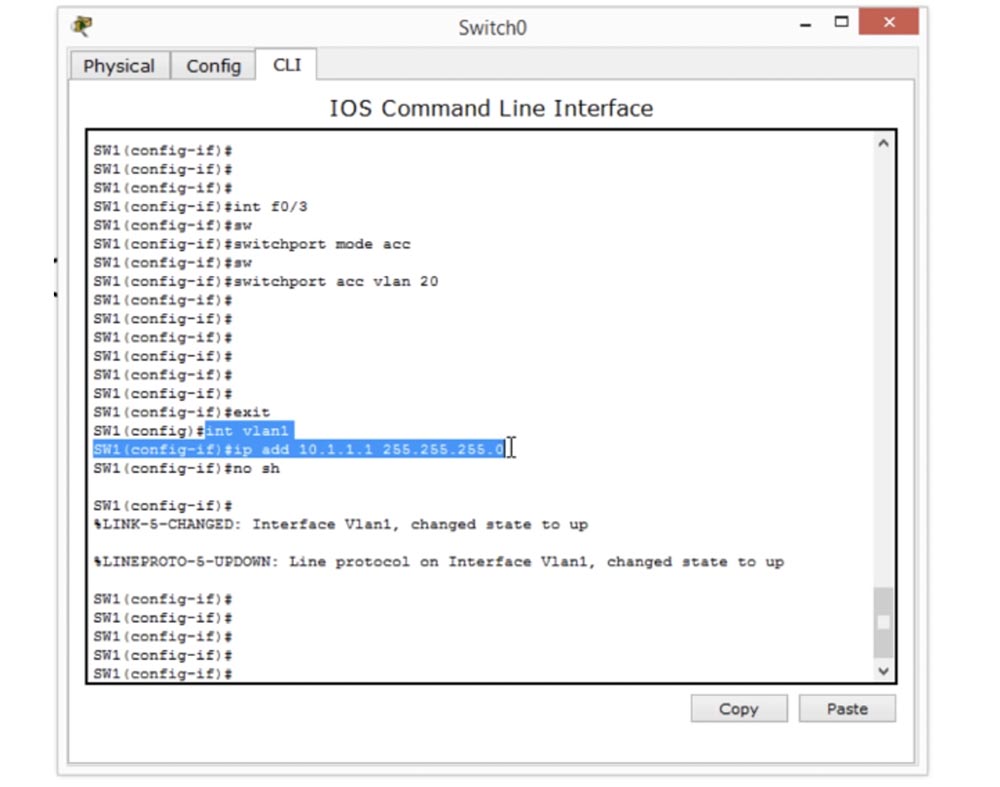
The last thing I want to mention is the Management IP assignment that we talked about in the last lesson. To do this, we use the int vlan1 command and enter the IP address 10.1.1.1 and the subnet mask 255.255.255.0, and then add the no shutdown command. We assigned Management IP not for the entire switch, but only for VLAN1 ports, that is, we assigned the IP address from which VLAN1 is managed. If we want to manage VLAN2, we need to create an appropriate interface for VLAN2. In our case, there are blue ports VLAN10 and orange ports VLAN20, which correspond to the addresses 192.168.1.0 and 192.168.2.0.
VLAN10 must have addresses located in the same range so that the corresponding devices can connect to it. The same setup should be made for VLAN20.
This switch command line window shows the interface settings for VLAN1, that is, the native VLAN.
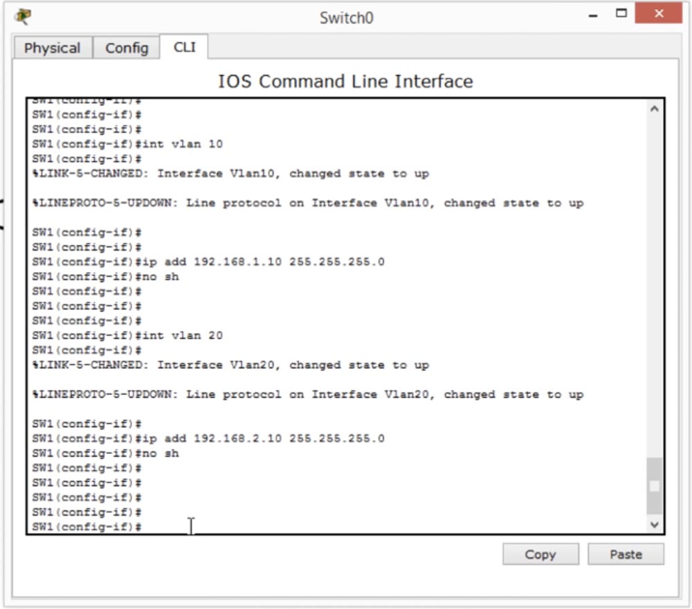
In order to configure Management IP for VLAN10, we need to create an interface int vlan 10, and then add the IP address 192.168.1.10 and the subnet mask 255.255.255.0.
To configure VLAN20, we need to create an interface int vlan 20, and then add the IP address 192.168.2.10 and the subnet mask 255.255.255.0.
Why do you need it? If PC0 and the upper left port of switch # 0 belong to the 192.168.1.0 network, PC2 belongs to the 192.168.2.0 network and is connected to the native port VLAN1, which belongs to the 10.1.1.1 network, PC0 cannot establish communication with this switch via the protocol SSH, because they belong to different networks. Therefore, in order for PC0 to connect to the switch via SSH or Telnet, we must give it Access. That's why we need network management.
We should be able to associate PC0 using SSH or Telnet with the IP address of the VLAN20 interface and make any changes we need via SSH. Thus, Management IP is needed precisely to configure the VLAN, because each virtual network must have its own access control.
In today's video, we discussed a lot of issues: basic switch settings, creating VLANs, assigning VLAN ports, assigning Management IP to VLANs, and configuring trunks. Do not be embarrassed if you do not understand something, this is natural, because VLAN is a very complex and extensive topic, to which we will return in the next lessons. , «» VLAN, , 3 : VLAN, .
, . ? ? , 30% entry-level , : VPS (KVM) E5-2650 v4 (6 Cores) 10GB DDR4 240GB SSD 1Gbps $20 ? ( RAID1 RAID10, 24 40GB DDR4).
Dell R730xd 2 ? 2 Intel TetraDeca-Core Xeon 2x E5-2697v3 2.6GHz 14C 64GB DDR4 4x960GB SSD 1Gbps 100 $199 ! Dell R420 — 2x E5-2430 2.2Ghz 6C 128GB DDR3 2x960GB SSD 1Gbps 100TB — $99! . c Dell R730xd 5-2650 v4 9000 ?
So, today we will talk about the basics of VLAN and answer 3 questions: what is VLAN, why do we need VLAN and how to configure it. I hope that after watching this video you can answer all three questions.
What is a VLAN? VLAN is an abbreviation of the name “virtual local area network”. Further down the course of our lesson, we will look at why this network is virtual, but before we go to the VLAN, we need to understand how the switch works. We will repeat some of the questions that were discussed in previous lessons.
')
We first discuss what constitutes a Multiple Collision Domain, or a collision domain. We know that this 48-port switch has 48 collision domains. This means that each of these ports or devices connected to these ports can interact with another device on another port independently, without affecting each other.
All 48 ports of this switch are part of the same broadcast domain Broadcast Domain. This means that if several devices are connected to several ports, and one of them is broadcasting, it will appear on all ports to which other devices are connected. This is how the switch works.
It is as if people were sitting in one room close to each other, and when one of them says something loudly, everyone else hears it. However, this is completely ineffective - the more people will appear in the room, the noisier it will become and those present will no longer hear each other. A similar situation arises with computers - the more devices are connected to the same network, the greater the “loudness” of the broadcasting becomes, which makes it impossible to establish an effective connection.
We know that if one of these devices is connected to the 192.168.1.0/24 network, all other devices are part of the same network. The switch must also be connected to the network with the same IP address. But here the switch as a device OSI level 2 may have a problem. If two devices are connected to the same network, they can easily connect to each other’s computers. Suppose that in our company there is a “bad guy”, a hacker, whom I will draw on top. Below it is my computer. So, this hacker is very easy to get into my computer, because our computers are part of the same network. That is the problem.
If I belong to the executive management, and this new guy will be able to access files on my computer, it will not be good at all. Of course, there is a firewall on my computer that protects against many threats, but a hacker will not be able to bypass it.
The second danger that exists for all who are members of this broadcast domain is that if someone has a broadcast problem, this interference will affect other devices on the network. Although all 48 ports can be connected to different hosts, the failure of one host will affect the other 47, which we do not need at all.
To solve this problem, we use the concept of VLAN, or VLAN. It works very simply, dividing this one big 48-port switch into several smaller switches.
We know that subnets divide one large network into several small networks, and VLAN works in a similar way. It divides the 48 – and port switch, for example, into 4 switches with 12 ports, each of which is part of a new interconnected network. At the same time, we can use 12 ports for management, 12 ports for IP-telephony and so on, that is, to divide the switch not physically, but logically, virtually.
I selected three ports of the upper switch, marked in blue, for the “blue” VLAN10 network, and I assigned three orange ports to VLAN20. Thus, any traffic from one of these blue ports will flow only to the other blue ports, without affecting the other ports of this switch. Traffic from the orange ports will be distributed in the same way, that is, we are supposed to use two different physical switches. Thus, VLAN is a way of splitting a switch into several switches for different networks.
I drew two switches from above, here we have a situation where only the blue ports for one network are involved on the left switch, and only orange for the other network on the right switch, and these switches are in no way connected to each other.
Let's say you go to use more ports. Imagine that we have 2 buildings, each of which has its own management staff, and two orange ports of the lower switch are used for management. Therefore, we need these ports to be connected to all the orange ports of other switches. The situation is similar with blue ports - all blue ports of the upper switch must be connected to other ports of the same color. To do this, we need to physically link these two switches in different buildings with a separate communication line; in the figure this is the line between the two ports in green. As we know, if two switches are physically connected, we will have a trunk, or trunk.
What is the difference between a normal and VLAN switch? This is not a big difference. When you buy a new switch, by default all ports are configured for VLAN mode and are part of the same network, denoted as VLAN1. That's why when we connect a device to one port, it is connected to all other ports, because all 48 ports belong to the same virtual network VLAN1. But if we configure the blue ports to work on the VLAN10 network, the orange ports on the VLAN20 network, and the green ports on the VLAN1 network, we will get 3 different switches. Thus, the use of the virtual network mode allows us to logically group ports for specific networks, divide the broadcast into parts and create subnets. In addition, each of the ports of a particular color belongs to a separate network. If the blue ports work on the 192.168.1.0 network and the orange ports work on the 192.168.1.0 network, in spite of the same IP address, they will not be connected to each other, because they will logically belong to different switches. And as we know, different physical switches do not communicate with each other unless they are connected by a common line of communication. Thus, we create different subnets for different VLANs.
I want to draw your attention that the concept of VLAN applies only to switches. Anyone familiar with encapsulation protocols, such as .1Q or ISL, knows that neither routers nor computers have any VLANs. When you connect your computer, for example, to one of the blue ports, you do not change anything in the computer, all changes occur only at the second level of OSI, the switch level. When we configure ports to work with a specific VLAN10 or VLAN20 network, the switch creates a VLAN database. It “writes” to itself in memory that ports 1,3 and 5 belong to VLAN10, 14,15 and 18 ports are part of the VLAN20 network, and the other ports involved are parts of the VLAN1 network. Therefore, if some traffic originates from blue port 1, it only hits ports 3 and 5 of the same VLAN10 network. The switch “looks” into its database and sees that if traffic comes from one of the orange ports, it should only go to the orange ports of the VLAN20 network.
However, the computer does not know anything about these VLANs. When we connect 2 switches, a trunk is formed between the green ports. The term “trunk” is relevant only for Cisco devices, the rest of network device manufacturers, such as Juniper, use the term Tag port, or “tagged port”. I think the name Tag port is more appropriate. When traffic flows from this network, the trunk transmits it to all ports of the next switch, that is, we connect two 48-port switches and receive one 96-port switch. At the same time, when we send traffic from VLAN10, it becomes tagged, that is, supplied with a label that indicates that it is intended only for VLAN10 ports. The second switch, having received this traffic, reads the tag and understands that this traffic is for VLAN10 and should only go to the blue ports. Similarly, the “orange” traffic for VLAN20 is provided with a tag that indicates that it is intended for VLAN20 ports of the second switch.
We also mentioned encapsulation, and there are two encapsulation methods here. The first is .1Q, that is, when we organize a trunk, we need to provide encapsulation. The encapsulation protocol .1Q is an open standard describing the traffic tagging procedure. There is another protocol called ISL, the Inter-Switch link, developed by Cisco, which indicates that a particular VLAN is belonging to traffic. All modern switches work with the .1Q protocol, therefore, taking a new switch out of the box, you do not need to use any encapsulation commands, because by default it is implemented by the .1Q protocol. Thus, after creating a trunk, traffic is automatically encapsulated, which allows you to read tags.
Now let's get down to setting up a VLAN. Let's create a network in which there will be 2 switches and two end devices - computers PC1 and PC2, which we will connect with cables with switch # 0. Let's start with the basic settings of the Basic Configuration switch.
To do this, click on the switch and go to the command line interface, and then set the host name, naming this switch sw1. Now let's move to the settings of the first computer and set the static IP address 192.168.1.1 and the subnet mask 255.255. 255.0. The default gateway address is not needed, because all our devices are on the same network. Next, we will do the same for the second computer, assigning it the IP address 192.168.1.2.
Now back to the first computer to ping the second computer. As you can see, pinging went well because both of these computers are connected to the same switch and are part of the same network by default VLAN1. If you look at the switch interfaces now, we will see that all FastEthernet ports from 1 to 24 and two GigabitEthernet ports are configured for VLAN # 1. However, such excessive availability is not needed, so we enter the switch settings and enter the show vlan command to look at the virtual network database.
You see here the name of the VLAN1 network and the fact that all ports of the switch belong to this network. This means that you can connect to any port, and all of them will be able to “communicate” with each other, because they are part of the same network.
We will change this situation, for this we first create two virtual networks, that is, add VLAN10. To create a virtual network, use the “vlan network number” command.
As you can see, when trying to create a network, the system issued a message listing the VLAN configuration commands that should be used for this action:
exit - apply changes and exit settings;
name — enter a custom VLAN name;
no - cancel the command or set it as default.
This means that before you enter the command to create a VLAN, you must enter the command name, which includes the name management mode, and then proceed to create a new network. In this case, the system prompts that the VLAN number can be assigned in the range from 1 to 1005.
So, now we enter the command to create a VLAN at number 20 - vlan 20, and then give it a name for the user, which shows what kind of network it is. In our case, we use the name Employees command, or the network for company employees.
Now we need to assign a specific port to this VLAN. We enter the int f0 / 1 switch settings mode, then manually switch the port to Access mode using the switchport mode access command and specify which port to switch to this mode — this is the port for the VLAN10 network.
We see that after this, the color of the PC0 junction point and the switch, the port color, changed from green to orange. It will turn green again as soon as the settings change takes effect. Let's try to ping the second computer. We did not make any changes to the network settings for computers; they still have the IP addresses 192.168.1.1 and 192.168.1.2. But if we try to ping PC1 from PC0, we will fail because now these computers belong to different networks: the first is to VLAN10, the second is to native VLAN1.
Let's go back to the switch interface and configure the second port. To do this, I will enter the int f0 / 2 command and repeat for VLAN 20 the same steps as for setting up the previous virtual network.
We see that now the lower port of the switch, to which the second computer is connected, also changed its color from green to orange - it takes several seconds before the changes in the settings take effect and it turns green again. If you ping the second computer again, it will not work, because the computers still belong to different networks, only PC1 is now not part of VLAN1, but VLAN20.
Thus, you have divided one physical switch into two different logical switches. You see that now the color of the port has changed from orange to green, the port is working, but it still does not ping because it belongs to another network.
Let's make changes to our scheme - disconnect PC1 from the first switch and connect it to the second switch, and connect the switches themselves with a cable.
In order to establish a connection between them, I will enter the settings of the second switch and create VLAN10, giving it the name Management, that is, the management network. Then I turn on Access mode and indicate that this mode is for VLAN10. Now the color of the ports through which the switches are connected has changed from orange to green because they are both configured for VLAN10. Now we need to create a trunk between both switches. Both of these ports are Fa0 / 2, so you need to create a trunk for the Fa0 / 2 port of the first switch using the switchport mode trunk command. The same must be done for the second switch, after which a trunk is formed between these two ports.
Now, if I want to ping PC1 from the first computer, everything will work out, because the connection between PC0 and switch # 0 is VLAN10, between switch # 1 and PC1 is also VLAN10, and both switches are connected by a trunk.
So, if the devices are located in different VLANs, then they are not connected to each other, and if in the same network, then free traffic can be exchanged between them. Let's try to add one more device to each switch.
In the network settings of the added PC2 computer, I will set the IP address to 192.168.2.1, and in the PC3 settings to the address 192.168.2.2. In this case, the ports to which these two PCs are connected will receive the designation Fa0 / 3. In the settings of the switch # 0 we set the Access mode and indicate that this port is for VLAN20, and do the same for switch # 1.
If I use the switchport access vlan 20 command, and the VLAN20 network has not yet been created, the system will generate an error like “Access VLAN does not exist”, because the switches are configured to work only with VLAN10.
Let's create VLAN20. I use the "show VLAN" command to view the virtual network database.
You can see that the default network is VLAN1, to which ports from Fa0 / 4 to Fa0 / 24 and Gig0 / 1, Gig0 / 2 are connected. Virtual network number 10 with the name Management is connected to port Fa0 / 1, and VLAN network number 20 with the default name VLAN0020 is connected to port Fa0 / 3.
In principle, the name of the network does not matter, as long as it does not repeat for different networks. If I want to replace the default network name that the system assigns, I use the command vlan 20 and name Employees. I can change this name to another, for example, to IPphones, and if we ping the IP address 192.168.2.2, we will see that the name of the VLAN does not matter.
The last thing I want to mention is the Management IP assignment that we talked about in the last lesson. To do this, we use the int vlan1 command and enter the IP address 10.1.1.1 and the subnet mask 255.255.255.0, and then add the no shutdown command. We assigned Management IP not for the entire switch, but only for VLAN1 ports, that is, we assigned the IP address from which VLAN1 is managed. If we want to manage VLAN2, we need to create an appropriate interface for VLAN2. In our case, there are blue ports VLAN10 and orange ports VLAN20, which correspond to the addresses 192.168.1.0 and 192.168.2.0.
VLAN10 must have addresses located in the same range so that the corresponding devices can connect to it. The same setup should be made for VLAN20.
This switch command line window shows the interface settings for VLAN1, that is, the native VLAN.
In order to configure Management IP for VLAN10, we need to create an interface int vlan 10, and then add the IP address 192.168.1.10 and the subnet mask 255.255.255.0.
To configure VLAN20, we need to create an interface int vlan 20, and then add the IP address 192.168.2.10 and the subnet mask 255.255.255.0.
Why do you need it? If PC0 and the upper left port of switch # 0 belong to the 192.168.1.0 network, PC2 belongs to the 192.168.2.0 network and is connected to the native port VLAN1, which belongs to the 10.1.1.1 network, PC0 cannot establish communication with this switch via the protocol SSH, because they belong to different networks. Therefore, in order for PC0 to connect to the switch via SSH or Telnet, we must give it Access. That's why we need network management.
We should be able to associate PC0 using SSH or Telnet with the IP address of the VLAN20 interface and make any changes we need via SSH. Thus, Management IP is needed precisely to configure the VLAN, because each virtual network must have its own access control.
In today's video, we discussed a lot of issues: basic switch settings, creating VLANs, assigning VLAN ports, assigning Management IP to VLANs, and configuring trunks. Do not be embarrassed if you do not understand something, this is natural, because VLAN is a very complex and extensive topic, to which we will return in the next lessons. , «» VLAN, , 3 : VLAN, .
, . ? ? , 30% entry-level , : VPS (KVM) E5-2650 v4 (6 Cores) 10GB DDR4 240GB SSD 1Gbps $20 ? ( RAID1 RAID10, 24 40GB DDR4).
Dell R730xd 2 ? 2 Intel TetraDeca-Core Xeon 2x E5-2697v3 2.6GHz 14C 64GB DDR4 4x960GB SSD 1Gbps 100 $199 ! Dell R420 — 2x E5-2430 2.2Ghz 6C 128GB DDR3 2x960GB SSD 1Gbps 100TB — $99! . c Dell R730xd 5-2650 v4 9000 ?
Source: https://habr.com/ru/post/458434/
All Articles