Micro-computer UKNTS Elektronika MS 0511 - installation of a DC-DC converter for powering the C2 (RS232)
Good day, comrades Habrovchane. Today I will continue my story about bringing my micro-computer UKNTS Electronics MS 0511 into a convenient form for use in the modern world.
The beginning of this story is here.
As I said earlier, the UKNTS is equipped with the Interface C2, which is a direct analogue of the RS-232C, which is remembered by all who found the 486th and earlier IBM PCs. Her Majesty Mouse was connected to this “magic 9-pin connector”, without which it was quite inconvenient to work in the creation of Billy Gates. An external modem squeaking into the telephone line was connected to the same connector so that the user could log in to the BBS. accept the FIDO newsletter or enter “These are your Internet” - download a book from Aldebaran or a porno from some secret file storage facility and download on the forum, chat in IRC. Ah, there were times where all these Twitter users with Telegrams were!
')
The same connector came to the rescue when it was necessary to connect a pair of computers to each other - a magic null modem cable.
But in spite of its more than respectable age - for the first time the RS-232 standard was proposed in 1962, and in 1969 the RS-232C standard was offered and is still today. Yes, of course, there is USB for a long time, which is now gradually moving to the 3.0 standard, but in industrial, server, military, telecommunications equipment and embedded systems there is still either an RS-232C connector, or somewhere hidden on the handkerchief an inconspicuous UART connector, or just pads for soldering his findings. To which you can connect the adapter to USB and from your laptop “to see what is going on in the system”, even if it seemed to be completely dead and through other interfaces nothing can be achieved from it.
In my UKSC, this same interface also exists, under the name Joint C2 adopted for it in the USSR. But since the interface works using + 12 / -12V levels for transmitting signals, the UKNTS board is powered only by + 5V - a DC-DC converter is needed, which would generate the necessary voltages applied to the 170AP2 and 170UP2 chips that directly match the TTL output of the UART controller 1801VP1 -065 with external devices signals ± 12V. These chips are soldered on my board, but to save money on a student's machine, the DC-DC converter was not soldered. It was believed that the student's UKSC would not be used for work through Joint C2, and if they were, then the converters could also be soldered.
A suitable DC-DC converter was selected and ordered in the Chip & Dip online store. I didn’t have to waste time on trifles and chose a model TMH 0512D capable of delivering 80 mA at the outputs and with short circuit protection.
Here is the link
But its datasheet
While the converter was driving to me, I turned to the collective mind of the Guru of the PDP-11 architecture on zx-pk.ru and sent me a photo of the nameplate from my native DC-DC installed once in the UKSC.
Photo nameplate converter.
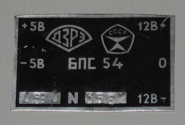
It is called BPS 54 and now probably is no place to buy it. Yes, and there is not much sense, the import will cope.
In the meantime, the converter, which had been ordered to Chip and Dip, successfully transferred to the journey with Russia Post thanks to a large strong box and many layers of cardboard inside, came to me. This is not the Chinese with their thin bags, they know how we handle parcels in the Post!
Photo import converter.
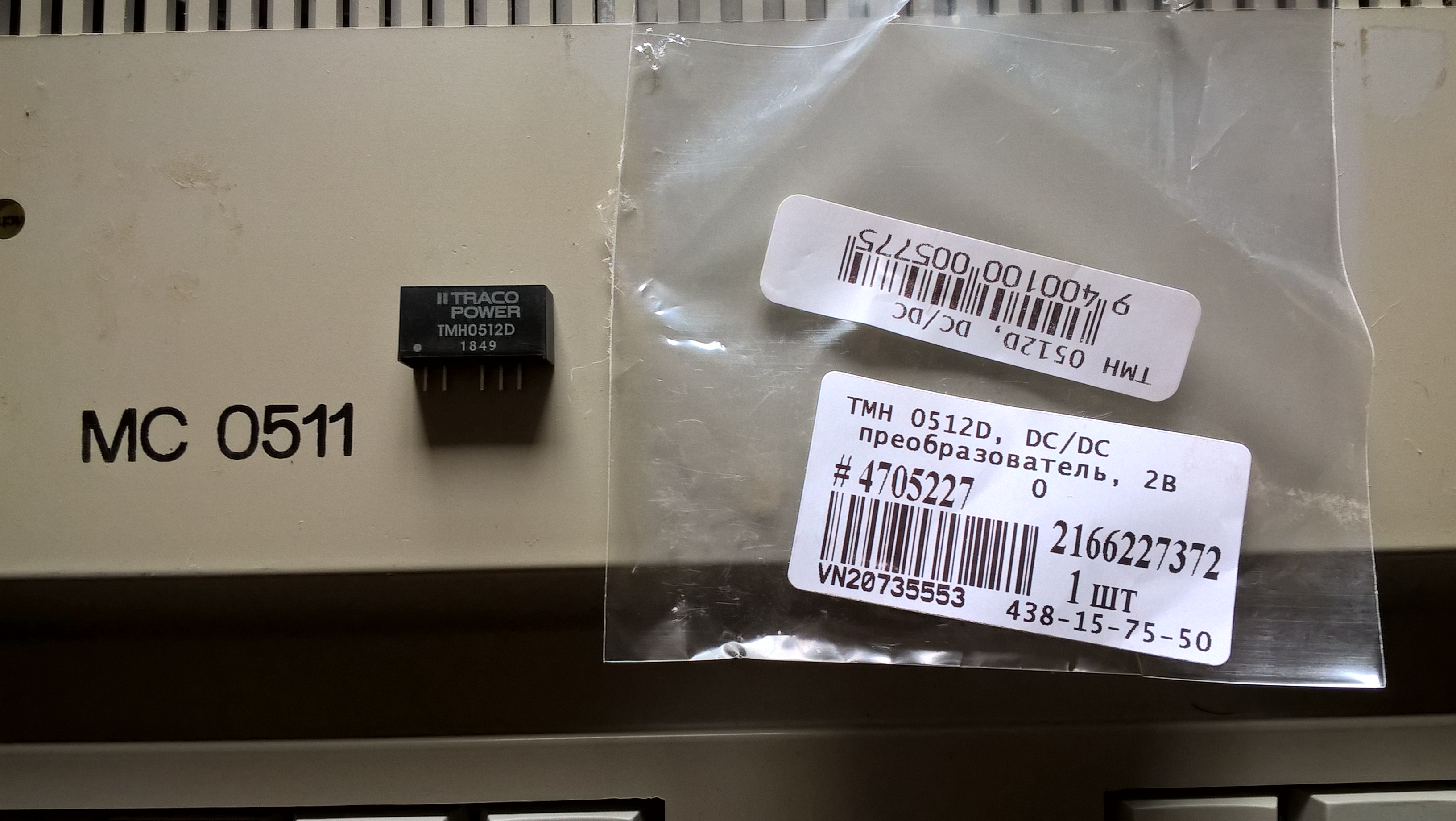
The very TMH 0512D.
Using the photo of the BPS 54 nameplate I made marks on the board where I should connect to what conclusions, so as not to poke constantly in the monitor re-checking my actions.
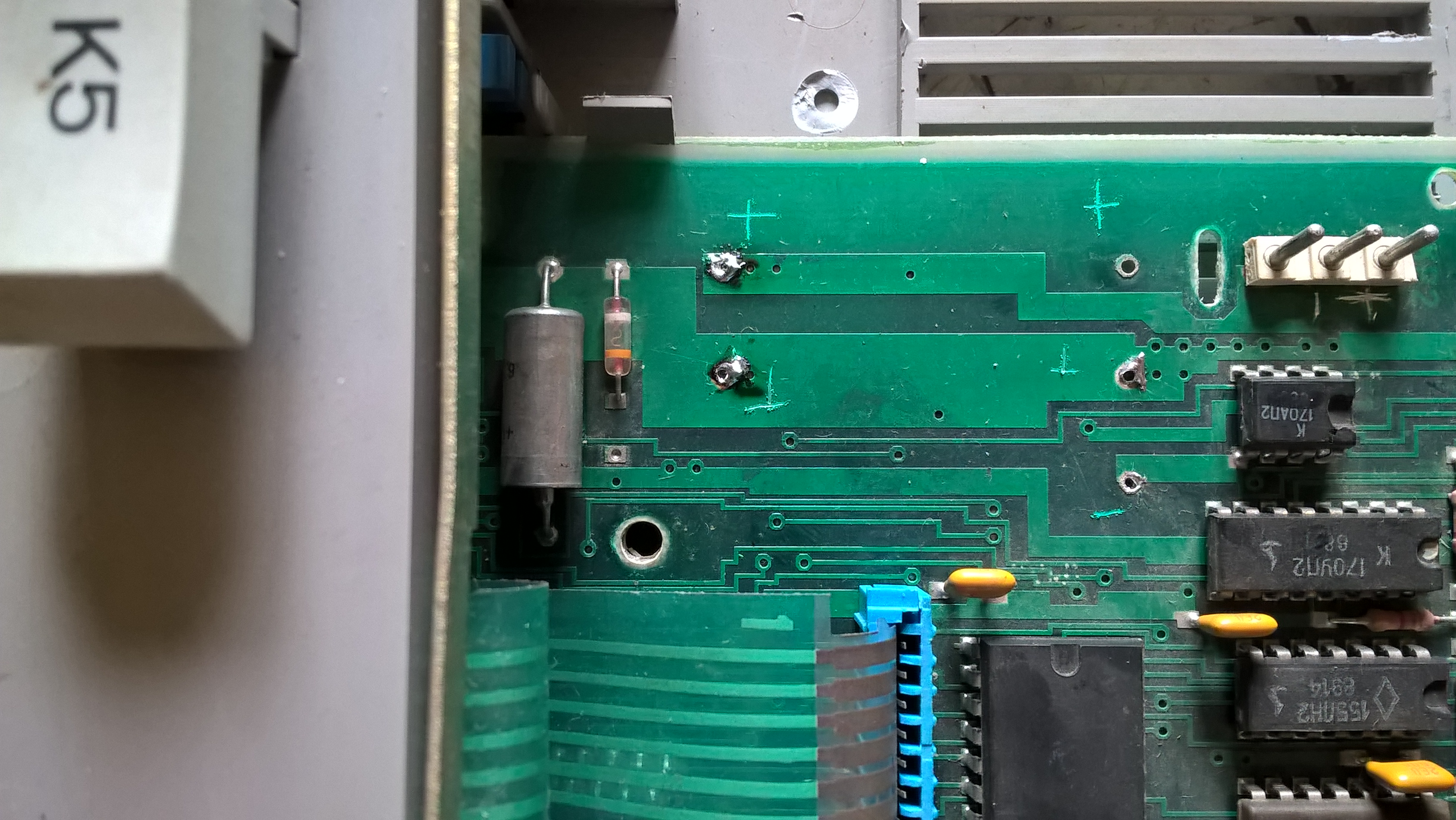
Fortunately, everything here is clearly done.
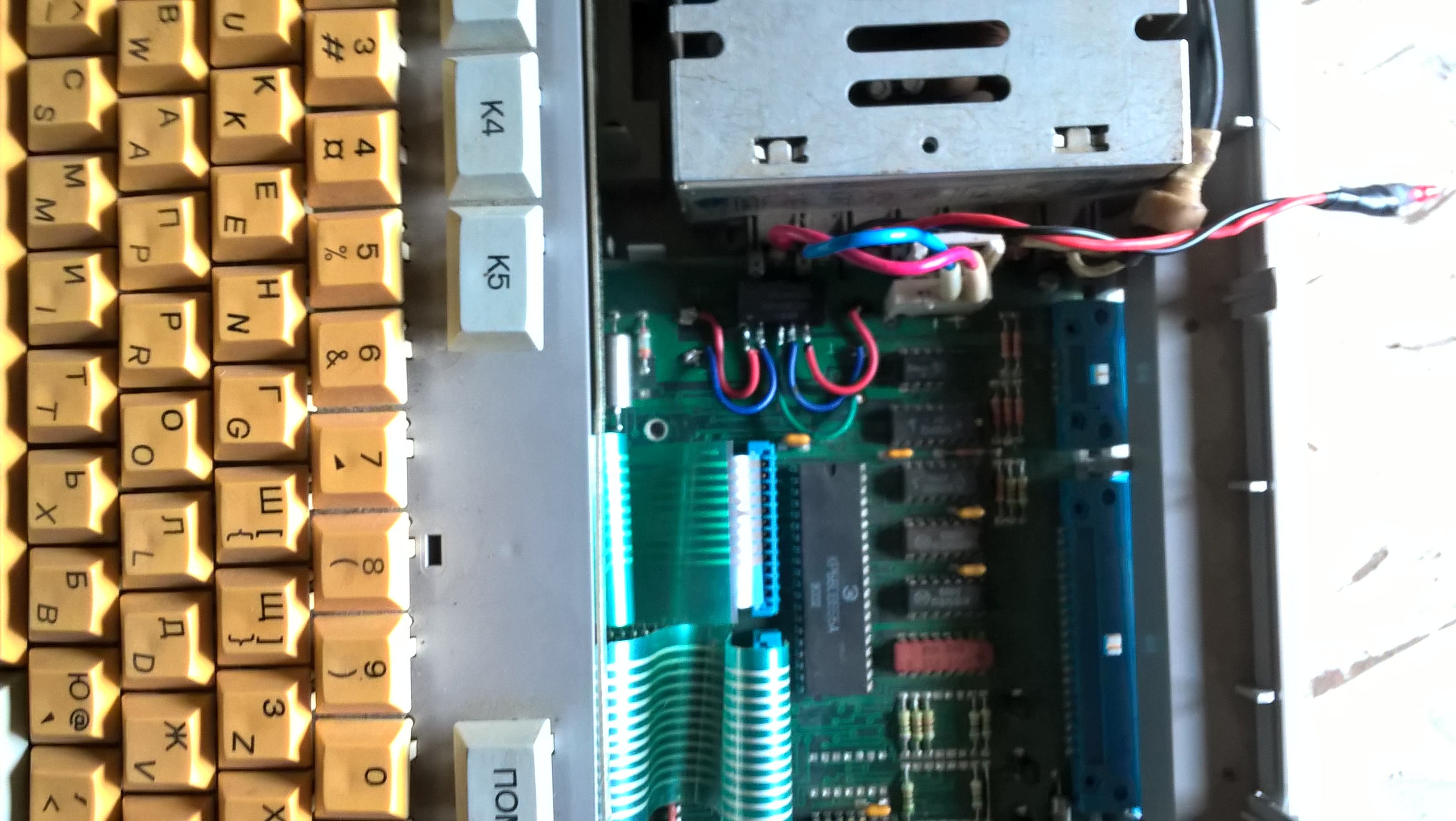
Further to the DC-DC converter, pieces of wires were soldered according to its datasheet. Red and blue pair - + 5V and GND, and green blue red - respectively -12 V GND + 12V. Then all the wires were soldered and the converter on a drop of hot melt adhesive was glued to the board.
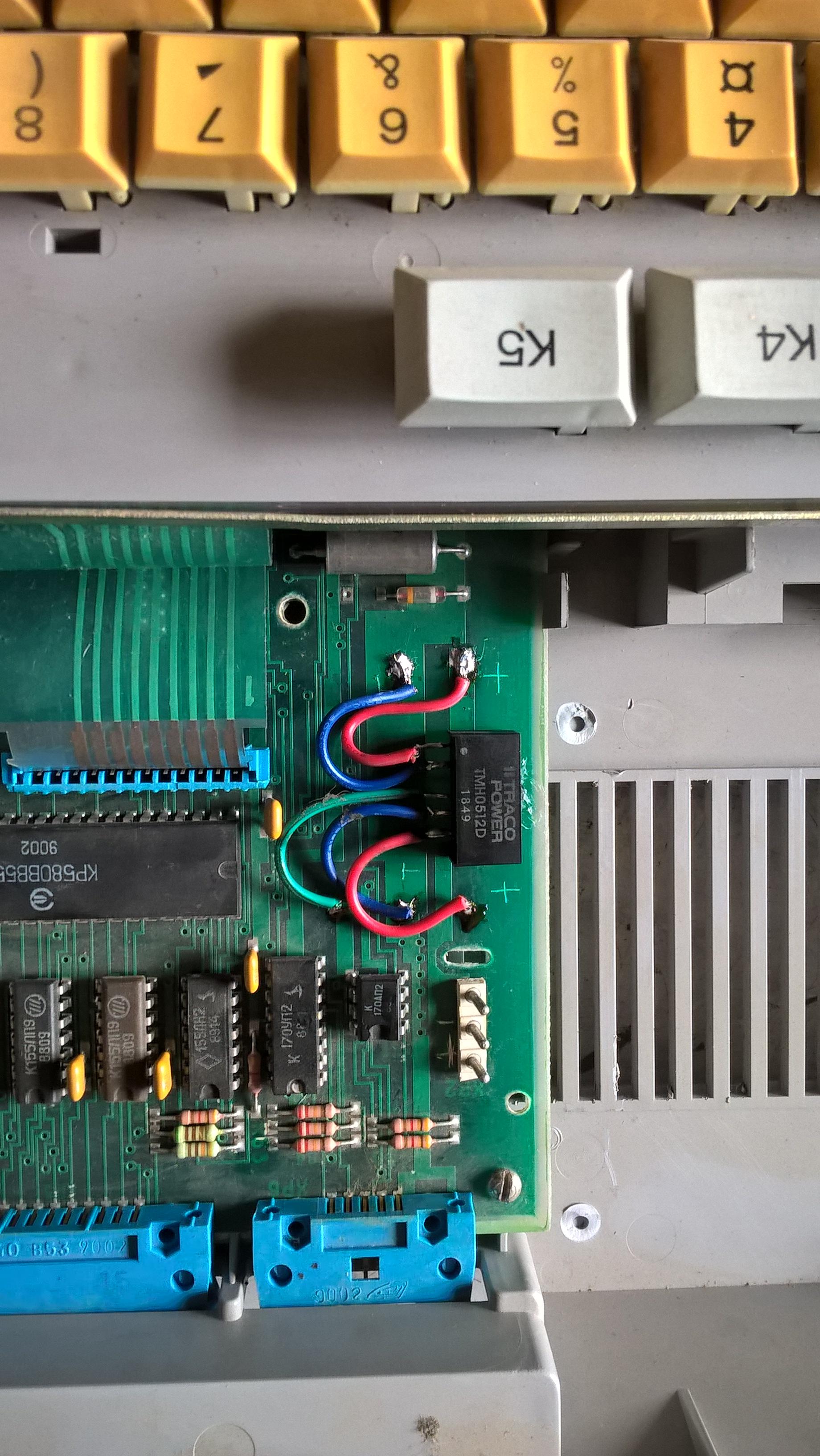
It is noticeably smaller than the Soviet, but it works just as well.
In its final form, everything looks like this.
Even with the power supply unit, the top cover was removed, which prevented the body from closing and the LED was glued all the same by hot melt adhesive in the hole in the body of the upper cover of the UFSC. It now remains to wait until the GBS-8220 arrives at the Post of Russia from China and connect a VGA monitor to the UKSC so that you can continue this story.
The beginning of this story is here.
As I said earlier, the UKNTS is equipped with the Interface C2, which is a direct analogue of the RS-232C, which is remembered by all who found the 486th and earlier IBM PCs. Her Majesty Mouse was connected to this “magic 9-pin connector”, without which it was quite inconvenient to work in the creation of Billy Gates. An external modem squeaking into the telephone line was connected to the same connector so that the user could log in to the BBS. accept the FIDO newsletter or enter “These are your Internet” - download a book from Aldebaran or a porno from some secret file storage facility and download on the forum, chat in IRC. Ah, there were times where all these Twitter users with Telegrams were!
')
The same connector came to the rescue when it was necessary to connect a pair of computers to each other - a magic null modem cable.
But in spite of its more than respectable age - for the first time the RS-232 standard was proposed in 1962, and in 1969 the RS-232C standard was offered and is still today. Yes, of course, there is USB for a long time, which is now gradually moving to the 3.0 standard, but in industrial, server, military, telecommunications equipment and embedded systems there is still either an RS-232C connector, or somewhere hidden on the handkerchief an inconspicuous UART connector, or just pads for soldering his findings. To which you can connect the adapter to USB and from your laptop “to see what is going on in the system”, even if it seemed to be completely dead and through other interfaces nothing can be achieved from it.
In my UKSC, this same interface also exists, under the name Joint C2 adopted for it in the USSR. But since the interface works using + 12 / -12V levels for transmitting signals, the UKNTS board is powered only by + 5V - a DC-DC converter is needed, which would generate the necessary voltages applied to the 170AP2 and 170UP2 chips that directly match the TTL output of the UART controller 1801VP1 -065 with external devices signals ± 12V. These chips are soldered on my board, but to save money on a student's machine, the DC-DC converter was not soldered. It was believed that the student's UKSC would not be used for work through Joint C2, and if they were, then the converters could also be soldered.
A suitable DC-DC converter was selected and ordered in the Chip & Dip online store. I didn’t have to waste time on trifles and chose a model TMH 0512D capable of delivering 80 mA at the outputs and with short circuit protection.
Here is the link
But its datasheet
While the converter was driving to me, I turned to the collective mind of the Guru of the PDP-11 architecture on zx-pk.ru and sent me a photo of the nameplate from my native DC-DC installed once in the UKSC.
Photo nameplate converter.
It is called BPS 54 and now probably is no place to buy it. Yes, and there is not much sense, the import will cope.
In the meantime, the converter, which had been ordered to Chip and Dip, successfully transferred to the journey with Russia Post thanks to a large strong box and many layers of cardboard inside, came to me. This is not the Chinese with their thin bags, they know how we handle parcels in the Post!
Photo import converter.
The very TMH 0512D.
Using the photo of the BPS 54 nameplate I made marks on the board where I should connect to what conclusions, so as not to poke constantly in the monitor re-checking my actions.
Fortunately, everything here is clearly done.
Further to the DC-DC converter, pieces of wires were soldered according to its datasheet. Red and blue pair - + 5V and GND, and green blue red - respectively -12 V GND + 12V. Then all the wires were soldered and the converter on a drop of hot melt adhesive was glued to the board.
It is noticeably smaller than the Soviet, but it works just as well.
In its final form, everything looks like this.
Even with the power supply unit, the top cover was removed, which prevented the body from closing and the LED was glued all the same by hot melt adhesive in the hole in the body of the upper cover of the UFSC. It now remains to wait until the GBS-8220 arrives at the Post of Russia from China and connect a VGA monitor to the UKSC so that you can continue this story.
Source: https://habr.com/ru/post/458402/
All Articles